Warlords Cocktail DP-177-1st-02A
Warlords (Atari, 1980) · Drawing Package · 1 pages · original scan
From MPU
Address Bus
Sheet 1, Side
Playfield Address Selector
©
From Syne | Sv “ rt Sheet 1, Side B
{t allows either t
and gates J6 and N9,
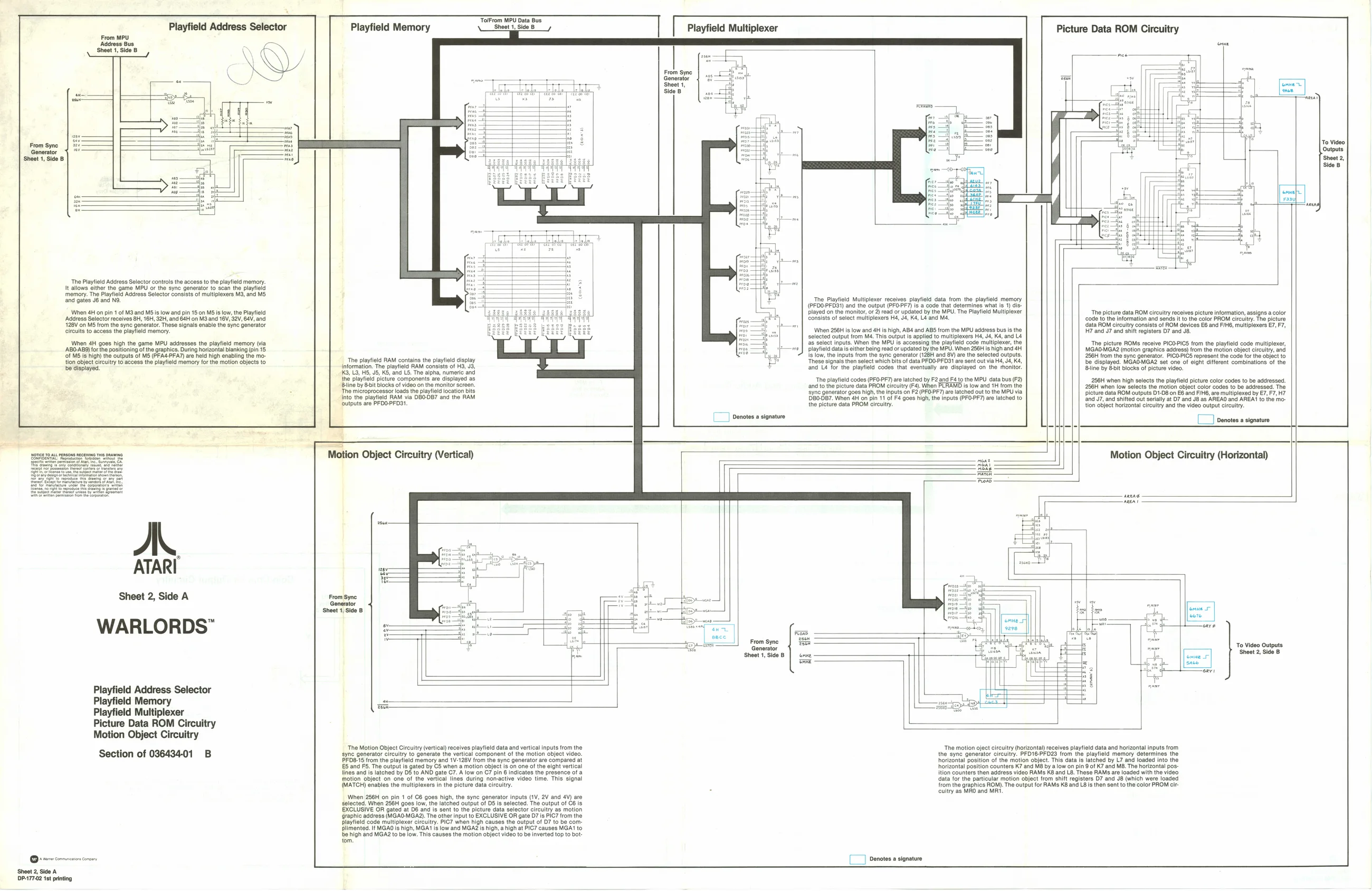
be displayed. ‘Address Selector controls the access tothe playfield memory. ‘game MPU or the sync generator to scan the playfield memory. The Playfield Address Selector consists of multiplexers M3, and MS
|When 4H on pin 1 of M3 and MS is iow and pin 18 on MS is low, the Playfield ‘Address Selector receives 8H, 18H, 32H, and 64H on M3 and 16V, 32V, 64V, and +128V on MS from the sync generator. These signals enable the sync generator circuits to access the playfield memory.
When 4H goes high the game MPU addresses the playfield memory (via 'AB0-AB9) for the positioning of the graphics. During horizontal blanking (pin 15. Cf MS is high) the outputs of MS (PFAG-PFA7) are held high enabling the motion object circuitry to access the playfield memory for the motion objects to
A.
ATARI
Sheet 2, Side A
WARLORDS”
Playtield Address Selector
Playfield Memory Playfield Multiplexer Picture Data ROM Circuitry Motion Object Circuitry
Section of 03643401 B
‘Sheet 2, Side A 1DP-177.02 1st printing TolFrom MPU Data Bus Sheet 1, Side B
‘The Motion Object Circuitry (vertical) receives playfield data and vertical inputs from the syne generator circuitry to generate the vertical component of the motion object video. PFDB-15 from the playfield memory and 1V-128V from the sync generator are compared at ES and FS. The output is gated by C5 when a motion object is on one of the eight vertical lines and is latched by DS to AND gate C7. A low on C7 pin 6 indicates the presence of a motion object on one of the vertical lines during non-active video time. This signal (MATCH) enables the multiplexers in the picture data circuitry.
When 256H on pin 1 of C8 goes high, the syne generator inputs (1V, 2V and 4V) are ‘selected. When 256H goes low, the latched output of DS is selected. The output of C6 is EXCLUSIVE OR gated at D6 and is sent to the picture data selector circuitry as motion ‘graphic address (MGAO-MGA2). The other input to EXCLUSIVE OR gate D7 is PIC7 from the Dlaytield code multiplexer circuitry. PIC7 when high causes the output of D7 to be com plimented. If MGAO is high, MGA1 Is low and MGAZ is high, ahigh at PIC7 causes MGA1 to ‘be high and MGA2 to be low. This causes the motion object video to be inverted top to bottom. ‘The motion oject circuitry (horizontal) receives playfield data and horizontal inputs from the sync generator circuitry. PFO16-PFD2S from the playfield memory determines the horizontal position of the motion object. This data is latched by L7 and loaded into the horizontal position counters K7 and M8 by alow on pin 9 of K7 and MB. The horizontal pos: ition counters then address video RAMs K8 and L8. These RAMs are loaded with the video ‘data for the particular motion object trom shift registers D7 and J8 (which were loaded from the graphics ROM). The output for RAMs K8 and LB is then sent to the color PROM circuitry as MRO and MRI
- oe
To video Outputs Sheet 2, Side 8
i ‘The Playfold Multiplexer receives playteld data trom the playtild memory Le {@FDO.PFOG!) and the output (PFOPF) isa code that determines what Is 1) dis-
| Lae | played on the monitor, oF 2) read or updated by the MPU. The Playfield Multiplexer | ‘The picture data ROM circuitry receives picture information, assigns a color | |
| Pra | apt | Eonsists of soleot multiplexers Hé, J, Ka, LA and Ma | code 16 the information and sends it to the color PROM circuitry. The picture |
a Gata ROM eircultry consists of ROM devices £8 and FIM6, multiplexers 7, FY,
| ot | ‘When 256H is low and 4H is high, ABA and ABS from the MPU address bus isthe | H7 and J7 and shift registers D7 and JB. | ||
| i) | Sp | selected output from MA. This output is appli to multiploxers H4,J4, Ka, and Lé | ||
| fer 4 | 235 select inputs. When the MPU ie accessing the plytield | code multiplexer, the | The picture ROMs receive PICO-PICS from the platilé code multiplexer, | |
| ist —8! | sf ne J plays datas | ether being ead or undated bythe MPU. When 256H is igh ana i | MGAGMGA2 (motion graphics address) from the motion | object crcultry, and |
ae {8 Tow, the Inputs from the syne genorator(128H and 8V) ae the selected outputs. 256H trom the sync ganerator. PICDPICS represent the code forthe object to
| ine ltl RAM contig tn lato nay | ‘These | signals then select which Dis of data PFOO-PFDS1 ae sent out va Ha 4, Ka, | be displayed. MGAOMGA2 set one of eight diferent combinations of the | ||||
| information. | The pay | consists of | HS, | and’ Lé for the | playlelé codes that eventually | are displayed on the thonitor | Biine by Bit Blocks of picture vid |
| 3, U3, H5 5, KS, | and LS, The alpha, numeri and | play! | ly | Dy BDIt | blocks | of picture | video. |
| the playlield picture | components are displayed as | ‘The playfield codes (PFO-PF7 are latched by F2.and F4to the MPU data bus (2) | 256H when high | selects the payleld picture color codes to be addressed | |||
| Bline by | Bt Blocks of video onthe monitor screen. | ‘and tothe picture data PROM circuitry (Fa) When PLRAWD | is low and 1H fom the | 256H when tow selects | the motion ebject color codes to be aderessed, The | ||
| ‘The microprocessor loads the playild location bits | Syne generator goes high, the Inputs on F2 (PFO-PF7) are latched out to the MPU via | pictur Jala ROM outputs D1.D8 on G8 and ETS re mulliploxed by EF, F7, HT | |||||
| into the playlielg RAM via DBO.DB7 and tho RAM | ‘DBOOB7. Wen aH on pn 11 of F4 goes high, the inputs (PFO-PF7) ae latched to | nd J?, ond shifted out serially at D7 and JB as AREAO and AREAT to ihe mo- | |||||
| Ouiputs are PFDO-PFOSI. | the picture data PROM elrculty | tion object horizontal circuitry and the video output clrcuty |
Denotes a signature [J] denote a signatre
= bt L Motion Object Circuitry (Vertical) = mene Motion Object Circuitry (Horizontal) Sea,
Fs
aneas
. ae
nee
From Syne F
Sheet 1, Side 8 shes te —
| “ | dou | ie | x | = | aa | nemo Liby | 28 | ies | eee |
| © | ho | J | ae ~ | i | ce | on | $$} | = | |
| ts | aim | Jo | . | ‘From Sync | od | om | | | ||
| t | A | Qeme | From Syne | To Video Outputs | |||||
| Shoot 1, Side B | | cove | | | (ae 8 | ‘Sheet 2, Side B |
toa sxce