Asteroids DP-143-6th-02A
Asteroids (rev 4) (Atari, 1979) · Drawing Package · 1 pages · original scan
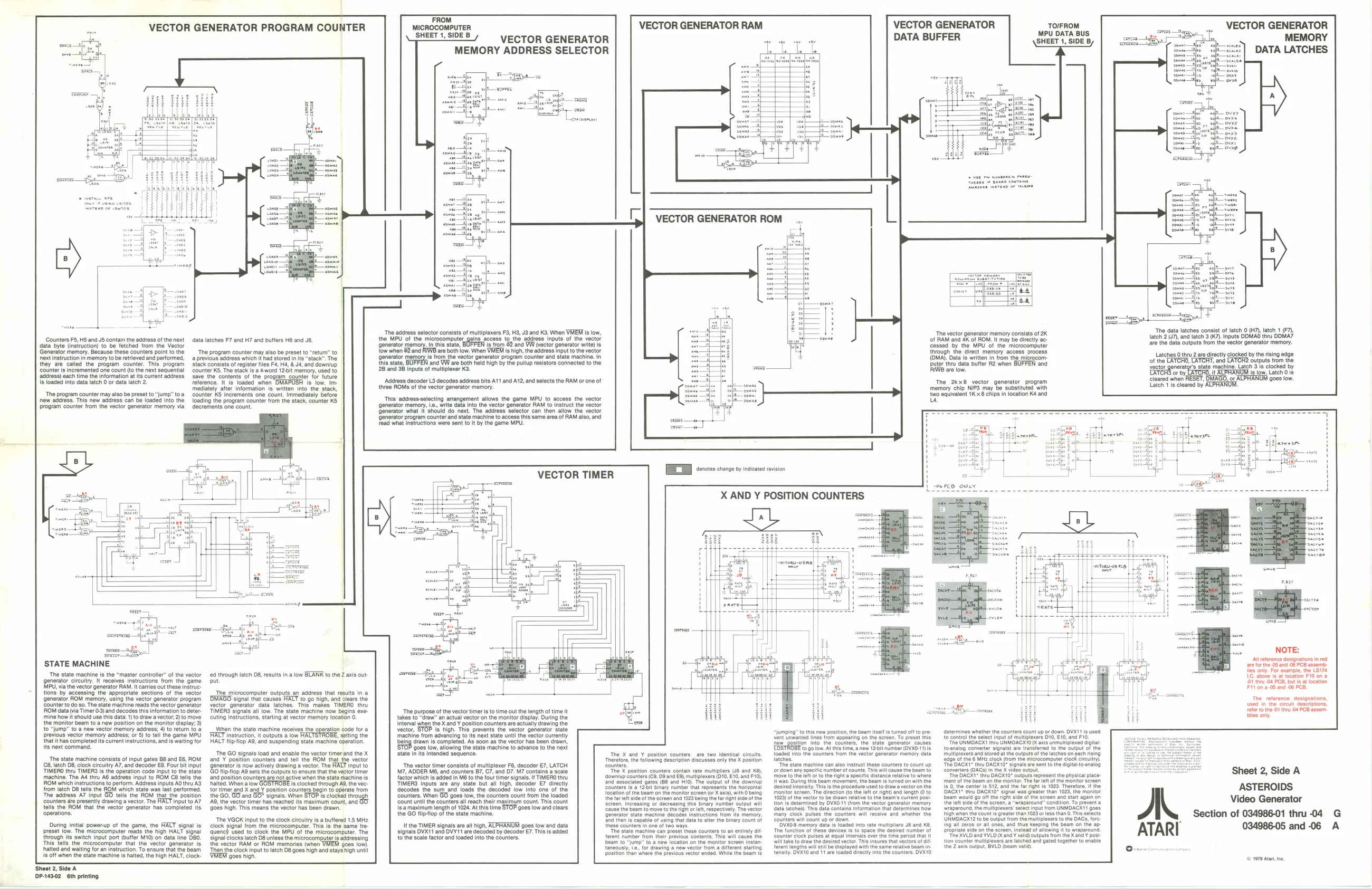
VECTOR GENERATOR PROGRAM COUNTER
Counters F5, HS and JS contain the address of the next
data byte (instruction) to be fetched from the Vector ‘Generator memory. Because these counters point to the next instruction in memory to be retrieved and performed, they are called the program counter. This. program Counter is incremented one count (to the next sequential ‘address) each time the information a its current address. Is loaded into data latch 0 or data latch 2.
‘The program counter may also be preset to “jump” toa
new address. This new address can be loaded into the program counter from the vector generator memory via data latches F7 and H7 and butfers HB and J6,
‘The program counter may aso be preset to return’ to
a previous adarose which t had stored inits"stack™ The Stack consits of register les Fa, & 4, and downup Gouna To ache a wad 12 ern, edo Save the contents of the. progam counter tor future Teforence. t's loaded when OMAPUSH fs low. ine mediately. aft counter KS Increments one count, Immediately befors Toading the program count ocr
Information is written into the stack,
from the stack, counter KS ‘one count.
STATE MACHINE
‘The state machine is the “master controller” of the vector generator circuitry. It receives instructions trom the game MPU, via the vector generator RAM. It carries out these instruc: tions’ by accessing the appropriate sections of the vector ‘generator ROM memory, using the vector generator program ‘Counter o do $0. The state machine reads the vector generator ROM data (via Timer 03) and decodes this information to deter ‘mine how it should use this dat: 1) to draw a vector; 2) to move the monitor beam to a new position on the monitor display 3) to “jump” to a new vector memory address; 4) to return to a Previous vector memory address; or 6) to tel the game MPU that ithas completed its current instructions, and is waiting for its next command. ‘The state machine consists of input gates 88 and E6, ROM 8, latch D8, clock circuitry A7, and decoder E8. Four bit input TIMERO thru TIMERS is the operation code input tothe state ‘machine. The A4 thru AG address input to ROM C8 tells th OM which instructions to perform. Address inputs AO thru AS from latch 8 tes the OM which state was last performed. “The address A7 input GO tells the ROM that the position counters are presently drawing a vector. The HALT input to A7 tells the ROM that the vector generator has completed its ‘operations.
tial power-up of the game, the HALT signa ‘The microcomputer reads the high HALT signal {rough its switch input port (buffer M10) on data line DBO. This tells the microcomputer that the vector generator is halted and waiting for an instruction. To ensure that the beam is off when the state machine is halted, the high HALT, clock: ‘Shoot 2, Side A P-14302 6th printing {4 through latch D8, results in a low BLANK to the Z axis out ut
The microcomputer outputs an address that results i signal that causes HALT to go high, and clears the yector generator data latches. This makes TIMERO thru TIMERS signals all low. The state machine now begins execcuting instructions, starting at vector memory location 0. When the state machine receiv lon code for a FAUT instction outputs @ tow HACTSTROBE, sating the HALT flipflop AS, and suspending state machine operation.
‘Te GO signals load and enable the vector timer and the x and’ ¥ positon counters and tell the ROM that the vector Generators now activeysrawing a vector. The BCfitop AS sets to outputs to ensure t tnd pealion counters arent arte wnen faa nen alow is clocked tough A, tortimer and X and ¥ position counters bagin to operate from the G0, GO end 60" Signals When STOP Ws clocked tough [8S the vector timer nas reached Its maximurh court, ang GO (oes nigh. This means the vector has been drawn. ‘The VGCK input to the clock circulty Is a buffered 1.5 MHz ‘lock signal from the microcomputer. This is the same fre ‘quenc} used to clock the MPU of the microcomputer. The signal clocks latch D8 unless the microcomputers addressing the vector RAM or ROM memories (when {goes low). “Then the clock input to latch 08 goes high and stays high until ‘9008 high, FROM MICROCOMPUTER SHEET 1, SIDE B
3, H3, J3 and K3. When VMEM Is ow, the MPU of the microcomputer gains access to the adaress inputs of the vector 'BOFFEN is trom $2 and generator. In this state, ‘WW (vector generator write) is ow when &2 and FUWB are both iow. When VMEM is high, the address input to the vector generator memento te vector generator program counter and state machine In this state, ‘and VW are both held high by the pullup resistors connected to the 2B and 38 Inputs of multiplexer K3. ‘Address decoder L3 decodes address bits A11 and A12, and selects the RAM or one of three ROMS of the vector generator memory.
This addressselecting arrangement allows the game MPU to access the vector ‘generator memory, write data into the vector generator RAM to Instruct the vector Generator what it'should do next. The address selector can then allow the vector ‘Generator program counter and state machine to access this same area of RAM also, and ead what instructions were sent to It by the game MPU. VECTOR GENERATOR MEMORY ADDRESS SELECTOR VECTOR GENERATOR RAM VECTOR GENERATOR DATA BUFFER TOIFROM MPU DATA BUS SHEET 1, SIDE B,
‘The vector generator memory consists of 2K of RAM and 4K of ROM. It may be directly acessed by the MPU of the microcomputer through the direct memory access process (DMA). Data is written in from the microcom-
VECTOR TIMER
Rearieers DButer thru data buffer F2 when BUFFEN and AMIS are low.
The 2kx8 vector generator program memory chip NIPS may be substituted with {wo equivalent 1K x8 chips in location K4 and us
‘The purpose of the vector timer sto time out the length of time it takes to "draw" an actual vector on the monitor display. During the Interval when the X and Y position counters are actually drawing the vector, STOP is high. This prevents the vector generator state ‘machine from advancing to its next state until the vector currently ‘boing drawn is completed. As soon as the vector has been drawn, ‘9028 low, allowing the state machine to advance to the next ‘tate In its Intended sequence.
“The vector timer consists of multiplexer F6, decoder E7, LATCH M7, ADDER M6, and counters 87, C7, and D7. M7 contains a scale facior which Is added in MB to the four timer signals. If TIMERO thru TIMERS Inputs are any state but all high, decoder E7 directly decodes the sum and loads the decoded low into one of the ‘counters. When GO goes low, the countere count from the loaded ‘count uni the counters all each their maximum count. This count Is amaximum length of 1024 At this time STOP goes low and clears the GO fliptop of the state machine. If the TIMER signals are all high, ALPHANUM goes low and data signals DVX11 and DVY'11 are decoded by decoder E7. Ths is added tothe scale factor and loaded into the counters. fe two identical circuts. sses only the X postion The X and ¥ position counters ‘Thoreore, the following description di
‘The X position counters contain rate multipliers JB and Xs), <downlup counters (€9, D8 and €9), multiplexers (010, E10, and F10), land associated gates (68 and #10). The output of the downlup Counters is. a 12>bit binary number that represents the horizontal location af the Beam on the monitor serean fr X ax), with 0 being ‘the fa ot sie of the screen and 1023 boing the far ight sige of Increasing or decreasing this bi
‘The state machine can preset these counters to an ently dit ferent number from thelr previous contents. This will cause the ‘beam t0."jump" to.a new location on the monitor screen ins taneously, Le. for rawing a new vector from a siffeent starting position than where the provious vector ended. While the boa 's "The tate machine ean algo instruct these counters to count up fordown any specific numberof counts. This will cause the bear to ‘move tothe let or to the right a speci dstance relative to where was. During tis beam movement, the bear is turnad on withthe Gesired intensity. Tiss the procedure used to draw avector on the
‘many clock pulses the counters. wil recelve and whether the ‘Counters will count up ot down. rs J8 and KB. red number of ‘petiog that it tore of dit tensity OVX10 and 11 are loaded directly into the counters, OVX coll
{ccunt up or down. DVX'1 is used ‘thru UNMOAGX10 (axis unrmltitexed digit, ) are transferred to the output of
{23g@.0f he.6 MHz clack (rom the microcompu ‘The DACX” thru DAGXIO" signals. Convertors (OACS) inthe X video output "The DAGXT" thru DACK10" outputs represent the physical place: ‘ment ofthe beam an the monitor. The fr felt of the monitor screen {8.0, tho center Te 512, and the far Nght Is 1023. Thoretoro, i the DAGXT® thru DAGX10® signal was greater than 1023, the rhonitor ne screen and start again on round” condition. To prevent & 'UNMOACXTT goes. ‘than 0, This selects to the DACs, fore clock circuitry) fattoanalog
high wren the counts greater than 1023 or UNMDAGX12 to be output from the multiple ing all 2er08 oF all ones, and thus keeping and YVLO (cand Y vali outputs from the Xand post ‘ultiplexers are latened and gated topetner to enable the Z axis output, BVLD (beam val VECTOR GENERATOR MEMORY
‘The data latches consist of latch 0 (H7), DATA LATCHES
latch 1.7), latch 2.7), and latch 3 (K7). Inputs DDMAG thru DDMA7 are the data outputs from the vector generator memory. Latches 0 thru 2 are directly clocked by the rising edge ot the vector generator’ stat or by, TATCHO, LATCH, and LATCH outputs from th te machine. Latch 3 is clocked by low. Latch 018. in Cleared wien RESET, DHAGO,o¢ ALPHANUM goes low. {atch is leared by ALPHANUM, °
erreurs 8 |
y, ATARI
(reut deserption Foter tthe 01 theu-04 PCB assem bile only
Sheet 2, Side A
ASTEROIDS Video Generator
Section of 034986-01 thru -04 034986-05 and -06
© 1079 At, ne.