Gondomania
Gondomania (World) (Data East Corporation, 1987) · Manual · 71 pages · 13 sections · original scan
operation : service
D EG DATA EAST USA, INC. ) WB 470 Needles Drive San Jose, California 95112 780-0063-00 May, 1987
WARNING
This equipment generates and uses radio frequency energy and if not installed and used properly, i.e., in strict accordance with the instructions manual, may cause harmful interference to radio communications. It has been tested and found to comply with the limits for a Class A computing device persuant to Subpart J of Part 15 of FCC Rules, which are designed to provide reasonable protection against such interference when operated in a commercial environment. Operation of this equipment in a residential area is likely to cause interference in which case the user at his own expense will be required to take whatever measures may be required to correct the interference.
GONDOMANIA
OPERATION AND SERVICE MANUAL
TABLE OF CONTENTS............-- ee see eee wee ceenecceee seeeed
WARNINGS AND DISCLAIMERS............... eee eeeeeee seeeeee eed
WARRANTY INFORMATION. .....--seeesesseeeceeee ee ee eee eee eeeee 1
GAME SET PROCEDURES
A. Inspecting the game.......... ©9886 ee tiers ee aoe eercceee eed
B. Set up and installation................. niet cee wes sane 2
SPECIFIC INFORMATION
A. Description of controls...
B. Operator selectable options...... B58 TS orden ecere ws wre ween ww 4
GENERAL INFORMATION
A. Sound volume control............ eee eecenae see e cece eee e nd
B. Power supply information...
C. Monitor adjustment information............... ee w 06
REPLACEMENT PARTS BREAKDOWN............ eee eee eee rere)
WIRING INFORMATION
A. Main harness diagram.... Ate eee eee renee seecee ceed
B. Joystick rotary control wiring..... eee c cece eee eneeeee 10
SCHEMATIC DIAGRAM REQUEST FORM..... See cee eee e cece ee enee 11
©1987 DATA EAST USA, INC. 470 Needles Drive San Jose, Ca. 95112 (408) 286-7074
1ST PRINTING
MAY 1987
WARNINGS AND DISCLAIMERS
FCC WARNING:
This equipment generates and uses radio frequency energy and if not installed and used properly, ie., in strict accordance with the instructions manual, may cause harmful interference to radio communications. It has been tested and found to comply with the limits for a Class A computing device pursuant to Subpart J of Part 15 of FCC Rules, which are designed to provide reasonable protection against such interference when operated in a commercial environment.
Operation of this equipment in a residential area is likely to cause interference in which the user at nis own expense will be required to take whatever measures may be required to correct the interference.
FBI WARNING:
Federal law provides severe civil and criminal penalties for the unauthorized reproduction, distribution, or exhibition of copyrighted audiovisual works and video games. The Federal Bureau of Investigation investigates allegations of criminal copyright infringement.
COPYRIGHT NOTICE:
Copyright 1987 by Data East Corporation, all rights reserved.
DISCLAIMER:
Data East USA, Inc., makes no warranty of any kind with regard to the accuracy of this material. Data East shall not be held liable for errors contained herein or for incidental or consequential damages in connection with the performance or use of this material. Data East reserves the right to change this material at any time without prior notice.
REPLACEMENT PARTS AND SERVICE:
To obtain replacement parts or technical assistance, contact the Data East distributor in your area. If you require further technical assistance, contact Data East's Service department between the hours of 8:00 am to 5:00 pm Pacific time at (408) 286-7074.
ii
- WARRANTY INFORMATION
Data East USA, Inc., ("Seller"), warrants only to the initial purchaser of its products that the items listed below are free from defects in material and workmanship under normal use and service for the warranty period specified:
- Printed Circuit Boards (game logic) (90) days
- Monitor pcb and CRT (30) days
- Switching Regulator (30) days
No other parts of Seller's products are warranted.
Warranty periods are effective from the initial date of shipment from Seller to its authorized distributors.
Seller's sole liability shall be, at its option, to repair or replace products which are returned to Seller during the warranty periods specified, provided:
- Seller is notified promptly upon discovery by buyer that stated products are defective.
- Such products are properly packaged and then returned, prepaid to Seller's plant.
This warranty does not apply to any parts damaged during shipping and/or handling, or due to improper installation or usage, or alteration. In no event shall the Seller be liable for any anticipated profits, loss of profits, loss of use, accidental or consequential damages or any other losses incurred by the customer in connection with the purchase of a Data East USA, Inc. product. .
WARRANTY DISCLAIMER
EXCEPT AS SPECIFICALLY PROVIDED IN A WRITTEN CONTRACT BETWEEN SELLER AND PURCHASER, THERE ARE NO OTHER WARRANTIES, EXPRESSED OR IMPLIED, INCLUDING ANY IMPLIED WARRANTIES OF MERCHANTABILITY OR FITNESS FOR A PARTICULAR PURPOSE.
pg 1
- GAME SET UP PROCEDURES.
A. Inspecting the game.
Gondomania is shipped from the factory in a padded, reinforced cardboard container. Before signing the delivery receipt, inspect the container for signs of abuse or damage. Do not sign the delivery receipt if you suspect that the game may be damaged. Open the container in the presence of the delivery driver, note any damage on the delivery receipt, and have the driver initial it before signing the receipt.
Inspect the exterior of the game for any damage to the cabinet. Open the coin door with the proper key. You will find the keys for the cashbox door and the rear access door hanging inside the coin door.
Remove the rear access door and check the following items:
- Check that all plug-in connectors are all firmly plugged in. Re-plug any connections found to be loose or unplugged.
- Check for secure mounting of the power supply, monitor, and coin door.
- Remove the power cord from inside the cabinet and insert the strain relief plate into the slot at the power cord opening in the cabinet.
Cc DO NOT PLUG IN THE POWER CORD AT THIS TIME a
B. Game installation.
Place the game in its intended location and stabilize it using the adjustable levelers built into the bottom of the cabinet.
Check the Operator Selectable Options information in section 3c of this manual and switch your game to the desired settings. The game is now ready to power up. Plug the game into a 117 VAC ‘grounded outlet and flip the power switch located on the power supply chassis to the ON position. Allow 2 to 3 minutes for the monitor filaments to warm up and check for proper attract mode video. Insert the proper coinage, start the game, check for proper control operation and audio response. Refer to section 3a for descriptions of control operation and game play.
If you detect any problems at this point, remove power to the game and contact your distributor for further instructions.
pg 2
- SPECIFIC INFORMATION
A. Description of controls.
The Gondomania game is equipped with two sets of controls, one each for the left (Blue Air Bike) player and another for the right (Grey Air Bike) player. Each set consists of a 8 way joystick with a 12 position rotary control, two types of fire buttons, and two start buttons. See the control panel layout for control placement.
i ‘ART SLACK IP PUSH 2 WHITE RED IP PUSH I BLACK 2p START <OYSTICK 2P PUSH 2 WHITE > 1P PUSH I ED 2P PUSH |
IP PUSH 2 WHITE JOYSTICK O O oe) FED 2P PUSH | WHITE 7 2P PUSH 2
Figure 1
The joystick controls the right, left, up, and down motion of the player image. The 12 position rotary control aims the player image's arm and is used in conjunction with the Push 1 button to fire in the direction the player image's arm is pointing. The Push 2 button causes a shot to be fired in a forward direction only.
The left coin mech credits the Blue Air Bike, and the right coin mech credits the Grey Air Bike. When the proper credits are provided, the left start button is used to begin play for Blue Air Bike, and the right start button will begin play for the Grey Air Bike.
C. Operator selectable options.
The operator selectable options are accessed via two banks of dip-switches located on the DE-0269 pcb. Be certain to remove power to the game when changing the settings of these switches to prevent unwanted electrical shock. Factory settings are noted with an *.
CREDIT:* CREDIT:
CREDIT:* OFF OFF CREDIT: ON OFF CREDIT: OFF ON CREDIT: ON ON. OFF Ce NOT USED ATTRACT MODE SOUND
FLIP SCREEN NORMAL: * FLIP:
NORMAL: *
GAME DIFFICULTY EASY: HARD: VERY HARD: CONTINUATION MODE YES :* ON NOT_USED OFF OFF OFF
pg 4
- GENERAL INFORMATION
A. Sound volume control.
The sound volume level is adjustable by turning the potentiometer VR1 on the main logic pcb. This can be accessed by opening the Coin Mech door and locating the potentiometer near the upper forward corner of the pcb set (See figure 2). Turn the control clockwise to increase the sound volume.
RAIN LOGIC PCB DE-2269-0
Figure 2
B. Power supply information.
The Power Supply assembly features an ON/OFF switch mounted on the Switch Bracket This switch must be in the OFF position before removing any components of the game or attempting any repairs to prevent unwanted electrical shock. There are also two fuses mounted next to the ON/OFF Switch. They are labeled as to their required ratings. If required, replace these fuses only with FAST BLOW fuses of the same current ratings. ‘
The 3 AMP FAST BLOW fuse is on the 117 VAC Line. In the event that this OFF/ON FUSE 3A FUSE IA fuse should blow, this will remove all power to the game. Check all harnessing for proper connections and look for obvious damage to the Monitor, Power Supply, and Logic pcb before replacing the fuse.
The 1 AMP FAST BLOW fuse is on the = = +12 VDC line to the Coin Door lamps. Figure 3 In the event that this fuse should blow, the lamps will not illuminate. Check for damaged Coin Door wiring and/or defective Coin Door lamp(s).
pg 5
The Switching Regulator's DC output level is adjustable by turning the potentiometer VR1. This adjustment should only be made while measuring the +5 volt level with a DIGITAL MULTI-METER at the LOGIC PCB, not at the SWITCHING REGULATOR!
C. Monitor adjustment information.
The Data East upright cabinet utilizes a Wells-Gardner 19K7602 RGB monitor display. The monitor adjustments are set at the factory for the optimum display. However, if adjustments are ever required, refer to figure 4 for control placement.
- BRIGHTNESS CONTROL VR6. Adjust this control so that the illumination is just barely extinquished from portions of the display which should be black.
- CONTRAST CONTROL VR7. Adjust the contrast control for the desired picture intensity.
- FOCUS CONTROL. Adjust the focus control, located on the high voltage unit T1, for maximum overall definition and fine picture detail.
- HORIZONTAL HOLD CONTROL VR2. With the monitor being driven with the display signal, connect a jumper between TP1 and TP2 and another jumper between TP3 and TP4. Adjust the horizontal hold control until the picture stops sliding horizontally. Remove the jumpers. Do not use the horizontal hold control for horizontal centering.
- HORIZONTAL VIDEO SHIFT CONTROL VR1. Use this control to center the picture horizontally.
- HORIZONTAL RASTER POSITION ADJUSTMENT. If the picture is off center horizontally, some compensation can be made by moving the horizontal raster position either to positions "R" or "L".
- HORIZONTAL SIZE COIL Li. The horizontal size coil is a hexagonal tuning tool adjustment. This control must be adjusted slowly, if necessary, until the picture or test pattern attains the correct horizontal proportions.
pg 6
- VERTICAL HOLD CONTROL VR5. Adjust this control until the picture stops rolling and it locks in vertically.
- 50-60 Hz CONTROL vR9. This control is used to limit the range of vertical size. This control is preset at the factory and should not require readjustment unless the vertical size or vertical hold controls are readjusted from their original factory settings. In order to set this control, first adjust the vertical size control so that the vertical size is slightly larger than desired. Turn VR9 so that any vertical fold-over which may be present will disappear.
- VERTICAL SIZE CONTROL. This control must be adjusted slowly, if Necessary, until the picture or test pattern attains the desired vertical proportions.
- VERTICAL RASTER POSITION CONTROL VR3. If the video is off center vertically, some compensation can be made by turning the vertical position raster control.
- CUT OFF AND DRIVE CONTROLS ON NECK BOARD VR201-VR206. These controls have been preset at the proper grey scale, adjustment of these controls should be avoided.
GREEN DRIVE
BLU CUT OFF HORIZ SIZE GREEN CUT OFF RED ORIVE
HORIZ RASTER POSITION FUSE d TPS TP4 TPS cH ‘SHUTi S bown RED. cuT OFF
HORIZ VIDEO. SHIFT HORIZ HOLD. VERT RASTER POS. VERT SIZE VERT HOLD BRIGHTNESS
Figure 4
pg 7
- REPLACEMENT PARTS BREAKDOWN
The following section lists the replacement parts available for the Gondomania upright game. You should include the Data East Part Numbers when ordering replacement parts from your distributor to help in expediting your orders promptly and accurately.
FINAL ASSEMBLY, GONDOMANIA U/R 500-0021-00
CABINET ASSEMBLY, 1US25-STYLE 365-0010-00 CONTROL PANEL ASSEMBLY 510-0111-00 COIN DOOR ASSEMBLY 515-0004-00 MONITOR ASSEMBLY, UNIVERSAL MOUNT 510-0065-00 POWER SUPPLY ASSEMBLY, 7A. 510-0002-00 PCB SET, GONDOMANIA 510-0112-00 PCB ASSY, EMI FILTER, DE-0239 520-0083-00 MAIN HARNESS, STD 2P 036-0117-01 DUAL LAMPHOLDER ASSEMBLY 170-0002-00 LAMP, INCANDESCENT, 40W 165-0004-01 PLEX RETAINER, MARQUEE 535-0009-00 PLEX, MARQUEE, GONDOMANIA 830-0031-00 PLEX, MONITOR, CLEAR, 23.75 X 23.75 660-0001-01 UNDERLAY CARD, GONDOMANIA 810-0025-00 LABEL, INSRUCTION, GONDMOMANIA 406-0064-00 SIDE DECAL, DE GEN. 5-13-87 830-0040-00 SPEAKER, 4" RND. 031-0004-00
CONTROL PANEL ASSEMBLY, GONDOMANIA 510-0111-00
CONTROL PANEL, BARE 535-0061-00 CONTROL PANEL OVERLAY, GONDOMANIA 800-0027-00 JOYSTICK, 8 WAY, ROTARY 450-0012-00 PUSHBUTTON ASSY, RED 350-0001-02 PUSHBUTTON ASSY, WHITE 350-0001-09 PUSHBUTTON ASSY, BLACK 350-0001-00 BUTTON HOLDER W/SWITCH 185-0001-00 PAL NUT 240-0001-00 KNOB, JOYSTICK, ROTARY 455-0047-00 SCREW, HEX, FOR JOYSTICK KNOB 235-0001-10
POWER SUPPLY ASSEMBLY, 7A. 510-0002-00
SWITCHING REGULATOR, 7A 001-0001-00 ISOLATION TRANSFORMER 010-0001-00 HARNESS, DC OUT, 7A 036-0031-02 NOISE FILTER 150-0004-00 POWER CORD 515-0002-00 SWITCH BRACKET ASSY. 515-0004-00
pg 8
5.
A.
cn-l WIRING DIAGRAMN
Main Harness diagram.
P2 DOWN P) vown LZ P2 UP Piup P2 LEFT PI LEFT P2 RIGHT Pi RIGHT P2 Puss Pi Push3
P2 PUSH! PI PUSH, | P2 PusH2
P2 SELECT Pi Sevect (11 COIN 2 coin \ OUNTER2 counter 1 [13] vt iit
il [|
x — a GND. 12] RicuT LEFT UP DOWN P) PUSH I PI PusH 2 PI PusHS CN-2
IP SELECT 2PSELECT
CP GND
GND COIN | cN-3
GND Coin 2
Hav cn-4 COuNTE
CRT BLUE Hl pi . eD CRT Sync. | CN-S- GND
gp tne
GND. Fav +5V
GND. CN-7
=5V +5v
B. Joystick rotary control wiring.
DE-8269-1 PCB
pg 10
- SCHEMATIC DIAGRAM REQUEST FORM
Technical Support Manuals with schematic diagrams are available by US Mail at no charge to owners of the Gondomania game. The Technical Support Manual contains schematic diagrams, pcb layout drawings, and parts lists for the Gondomania pcb set. To obtain your copy, fill out the information card below and mail to:
Data East USA, Inc. 470 Needles Dr. San Jose, CA. 95112
Attn: Customer Service Dept.
Also, if you have suggestions or comments regarding Data East's product, manuals, or other subjects, please feel free to include them in the comments section below. We count on your feedback to help us serve you better!
GONDOMANIA
TECHNICAL SUPPORT MANUAL REQUEST FORM
CUSTOMER NAME: TITLE:
COMPANY NAME:
STREET ADDRESS:
TELEPHONE NUMBER: { )
GAME SERIAL NUMBER: DATE:
YES! PLEASE ADD MY FIRM TO THE DATA EAST MAILING LIST.
NO! DO NOT ADD MY FIRM TO THE DATA EAST MAILING LIST.
COMMENTS:
pg 11
WARNING
Federal law provides severe civil and criminal penalties for the unauthorized reproduction, distribution, or exhibition of copyrighted audiovisual works and video games.
The Federal Bureau of Investigation
investigates allegations of criminal copyright infringement.
GONDOMANIA
TECHNICAL SUPPORT MANUAL
780-0065-00 jy 1987
WARNING
This equipment generates and uses radio frequency energy and if not installed and used properly, i.e., in strict accordance with the instructions manual, may cause harmful interference to radio communications. It has been tested and found to comply with the limits for a Class A computing device persuant to Subpart J of Part 15 of FCC Rules, which are designed to provide reasonable protection against such interference when operated in a commercial environment. Operation of this equipment in a residential area is likely to cause interference in which case the user at his own expense will be required to take whatever measures may be required to correct the interference.
TECHNICAL SUPPORT MANUAL
FOR
GONDOMANTIA
TABLE OF CONTENTS
- GENERAL INFORMATION a. Game Play & Player Control Description.
- COMPONENT LIST a. DE-0269 PCB........... b. DE-0259 PCB.... c. Eprom Checksums.. aeeeee a)
- PCB LAYOUT DIAGRAMS @. DE-0269 PCB... . cece cece e cee cece cece cece eee eees oT b. DE-0259 PCB.......... oe 8 ce. Wells-Gardner K7000 Monitor Chassis..............00000209
- SCHEMATIC DIAGRAMS......... ee
- WIRING DIAGRAMS............ te cece eee c cc eeeccccceccccce 2249
PREFACE
This manual is intended to be used by service technicians to aid in the diagnosis and repair of the Gondomania game. The manual presents game play, player control operation, operator selectable options, component lists, schematics, and more.
All programmed devices are listed with their checksums, to simplify verification of a device with a Eprom duplicator. See page Chapter 2c for additional information on using this data.
If you have any questions or suggestions regarding this publication, or if you require assistance with a Data East game, please call our Technical Service department at (408) 286-7074, Monday thru Friday, 8:00 am to 5:00 pm Pacific time. You may mail your comments to:
Data East USA, Inc. 470 Needles Inc. San Jose, CA. 95112 Attn: Technical Service
1l.- GENERAL INFORMATION
a. Game Play & Player Control Description.
The Gondomania game is equipped with two sets of controls, one each for the left (Blue Air Bike) player and another for the right (Grey Air Bike) player. Each set consists of a 8 way joystick with a 12 position rotary control, two types of fire buttons, and two start buttons. See the control panel layout for control placement.
Figure 1
The joystick controls the right, left, up, and down motion of the player image. The 12 position rotary control aims the player image's arm and is used in conjunction with the Push 1 button to fire in the direction the player image's arm is pointing. This weapon has unlimited firepower. The Push 2 button causes a limited (50 shots) amount of firepower to be fired in a forward direction only.
You can pick up additional firepower as the game progresses. Additioanl firepower and optional equipment can be purchased by collecting money received for destroying enemy targets, and flying over the object you desire. The cost of the object will be deducted from your accumulated money. If the object's cost is greater than the total money you have accumulated, you will not pick up the object or gain additional firepower.
The left coin mechanism credits the Blue Air Bike, and the right coin mechanism credits the Grey Air Bike. When the proper credits are provided, the left start button is used to begin play for Blue Air Bike, and the right start button will begin play for the Grey Air Bike.
Page 1
b. Operator Selectable Options.
The operator selectable options are accessed via two banks of dipswitches located on the DE-0269 pcb. Be certain to remove power to the game when changing the settings of these switches to prevent unwanted electrical shock. Factory settings are noted with an *.
TABLE 1.
DIPSWITCH 1 1 2 3 4 5 6 1 8 PLAYER 2 COIN = 1 CREDIT:* OFF OFF = 2 CREDIT: ON OFF = 3 CREDIT: OFF ON =_1 CREDIT: ON ON = 1 CREDIT:* OFF OFF = 2 CREDIT: ON OFF = 3 CREDIT: =
FLIP SCREEN
TABLE 2
DIPSWITCH 2 1 2 3 4 5 6 7 8 THREE:* OFF OFF NUMBER OF LIVES FIVE: ON OFF ONE: OFF ON INFINITE: ON ON NORMAL: * OFF OFF EASY: GAME DIFFICULTY
CONTINUATION MODE YES :* ON NOT_USED OFF OFF ___ OF.
Page 2
- COMPONENT LIstT
a. DE-0269 PCB
TYPE DEVICE ID PART NUMBER PCB LOCATION
TTL 74LS00 100-0025-00 25 TTL 7ALS02 100-0026-00 6D TTL T4804 100-0027-00 9E,7E,8E TTL T4LS08 100-0028-00 9D TTL 74LS10 100-0029-00 15E TTL 74LS27 100-0032-00 10A TTL TALS32 100-0034-00 4D,5E,6E TTL T4LS74 100-0037-00 11D,1E,3E TTL TALS86 100-0039-00 10D,14E TTL 74LS138 100-0042-00 15D TTL TALS139 100-0043-00 2D TTL 74LS153 100-0045-00 6A,7A,8A,9A,7B TTL 74LS157 100-0046-00 14 EA. (see pcb layout) TTL TALS174 100-0051-00 10C,16C,18C,8D,10E,12E TTL 74LS194 100-0055-00 3A,6K TTL TALS244 100-0057-00 3B,1D TTL TALS245 100-0058-00 5C,7C,8C,9C,13C,15C, 6d TTL 74LS257 100-0171-00 8J,93,103,123,133,153,163 TTL 74L8273 100-0022-00 13 EA (see pcb layout TTL T4LS283 100-0061-00 11A,13A,14A,10B TTL 74LS299 100-0220-00 11D,17E,18E,10F,11F,15F,16F TTL 74LS367 100-0062-00 4E TTL T4LS374 100-0064-00 1C,2C,3C,4C,6C CPU 6502A 100-0094-01 5d CPU 6809E 100-0189-01 1F CPU 8751H 960-0008-04 1B RAM TMM2015-15 105-0083-00 6H RAM TMM2018~-15 105-0035-00 5B,8B,9B,13E RAM HM6264-10 105-0051-02 16B OPN YM2203 100-0123-00 3F DAC YM3014 100-0179-00 1H, 2H OPL YM3526 100-0208-00 3H OP AMP MPC3403 100-0124-00 lg PWR AMP MB3730 100-0081-00 1k HYBRID RCDN-I1 100-0185-00 RA4,RAS ,RA6-RA13,RA20,RA21 HYBRID RM-C3 120-0066-00 RA1,RA2 XTAL 8 MHZ 140-0007-00 x1 XISTOR 2SD880 110-0044-00 Qi RESNET 1K xX 8 120-0039-20 RA3 RESNET 3.3K X 8 120-0037-26 RA16,RA17 RESNET 10K X 8 120-0039-32 RA22
Page 3
b. DE-0259 PCB
TYPE
TTL TTL TTL TTL TTL TTL TTL TTL TTL TTL TTL TTL TTL TTL TTL TTL TTL TTL TTL TTL TTL TTL TTL TTL TTL TTL TTL TTL CUSTOM IC cusTOM IC CUSTOM IC RAM LINEAR XTAL DEVICE ID
74LS00 74LS02 7404 TALSO4 TALSO8 74LS10 74LS14 TALS20 74L830 74LS32 74LS74 74LS86 74LS138 74LS157 7A4LS158 74LS163 74LS174 74LS175 7448194 TALS244 T4LS245 74LS257 74LS273 TALS 283 74LS373 TALS374 74L8375 7ALS669 HMC-20 VSC-30 DRL-40 TMM2018-55 PST-518 12 MHZ PART NUMBER
100-0025-00 100-0026-00 100-0007-00 100-0027-00 100-0028-00 100-0029-00 100-0030-00 100-0031-00 100-0033-00 100-0034-00 100-0037-00 100-0039-00 100-0042-00 100-0046-00 100-0047-00 100-0049-00 100-0051-00 100-0052-00 100-0055-00 100-0057-00 100-0058-00 100-0170-00 100-0022-00 100-0061-00 100-0111-00 100-0064-00 100-0173-00 100-0191-00 100-0159-00 100-0160-00 100-0221-00 105-0035-00 110-0065-00 140-0005-00
Page 4 PCB LOCATION
2B,1D,16E, 7K 2A 17A 1€,13C,14C,16C,9£,3L 3D,12C,15D,10E, 9M 7B 14a TE,9L 2D,8E 12E,10K 11 EA (see pcb layout) 13A,13B,9C,14D 12B 12 EA (see pcb layout) 6F,7F,8H,83,14H,14J, 7A,10A,11A,1D,2E 15C,3K,1L 10D,10M 17C,18C,17D,18D,11D 14B,73,133 4A,5A,17B,18B,15,16,17,18K 73,123,153,180 23,6K,8M 7TA,8A,7D,8D 103,110,163,179 26 EA (see pcb layout) 13D,16D,8L,10L 7C,8C 16A 11B 6M,12M 10 EA (see pcb layout) PST518 XTAL
c. Eprom Checksums.
This section lists the program devices (Eproms) used on the Gondomania pcb set. In addition, we have included the checksum of each device to allow verification of suspect devices with the aid of an Eprom duplicating machine. The checksum is a sum of all the programmed bytes in an Eprom and is unique to each individual program device. These checksums were generated using a Data I/O System 29B.
If you suspect a program device has failed, load its program into the duplicating equipment. Compare the checksum displayed with the data on the following list and verify that they match. In the event that your checksum does not match, check one or two other Eproms in the same manner to be certain that your duplicating equipment computes checksums in the same fashion.
DE-0269 PCB
| LABEL - DEVICE SUM | FUNCTION | PART NUMBER | ||
| DT-00 | 27256 | E9F2 | CPU PROGRAM | 960-0008-00 |
| DT-01 | 27512 | 068E | CPU PROGRAM | 960-0008-01 |
| DT-02 | 27512 | 62AA | CPU PROGRAM | 960-0008-02 |
| DT-03 | 27512 | 2424 | CPU PROGRAM | 960-0008-03 |
| DT-04 | 8751H | N/A | SECURITY CHIP | 960-0008-04 |
| DT-05 | 27256 | 9EFS | AUDIO PROGRAM | 960-0008-05 |
| DT-06 | 27512 | 2c79 | BACKGROUND GRAPHICS | 960-0008-06 |
| DT-07 | 27256 | E196 | BACKGROUND GRAPHICS | 960-0008-07 |
| DT-08 | 27512 | ED13 | BACKGROUND GRAPHICS | 960-0008-08 |
| DT-09 | 27256 | DFB8 | BACKGROUND GRAPHICS | 960-0008-09 |
| DT-10 | 27512 | 265C | BACKGROUND GRAPHICS | 960-0008-10 |
| DT-11 | 27256 | 1835 | BACKGROUND GRAPHICS | 960-0008-11 |
| DT-12 | 27512 | 6F21 | BACKGROUND GRAPHICS | 960-0008-12 |
| DT-13 | 27256 | 75D0 | BACKGROUND GRAPHICS | 960-0008-13 |
| DT-14 | 27256 | 07C6 | FOREGROUND COLOR | 960-0008-14 |
DE-0259 PCB
| DT-15 | 27512 | SA9F | MOVING OBJECT GRAPHICS | 960-0008-15 |
| DT-16 | 27512 | E8D8 | MOVING OBJECT GRAPHICS | 960-0008-16 |
| DT-17 | 27256 | SF4A | MOVING OBJECT GRAPHICS | 960-0008-17 |
| DT-18 | 27256 | F699 | MOVING OBJECT GRAPHICS | 960-0008-18 |
| DT-19 | 27512 | 9TF8 | MOVING OBJECT GRAPHICS | 960-0008-19 |
| DT-20 | 27256 | 7402 | MOVING OBJECT GRAPHICS | 960-0008-20 |
| DT~21 | 27512 | TCEQ | MOVING OBJECT GRAPHICS | 960-0008~-21 |
| DT-22 | 27256 | EFD6 | MOVING OBJECT GRAPHICS | 960-0008-22 |
Page 5
- PCB LAYOUT DIAGRAMS
a. DE-0269 PCB
=] ARTS MALE wi dn- daa
al] | Winans} gf Secor 40pm $ z : z |
UL. W t Uo ve
: . le [Js In :
| i | : | x | |
| 3 | + | HL + | lke |
3 Book
| 7 | . | s |
: ! Ii. LW ks
is wee Te a a
Bs LJ LJ :
heels 7 Enel D adh La: as oo d= 1 4d-adohs
Page 7
° . cE ES SS Ge Oe as : 5 ex eo SE) ee ee) ee oe) ==] = oT
i 2 3S ae ie ee) oe oe
@ ve : at Ge J ae) 78 } 2 B
This page carries no recoverable text. It is a drawing or a photograph. See the original scan.
- SCHEMATIC DIAGRAMS
a. DE-0269 PCB.................. obec cece cc cacencee +--page 11-30
b. DE-0259 PCB.................25 oe se eceees +-Ppage 31-47
ce. Wells-Gardner K7000 Monitor.......... te eeeeeecee seen eee 48
Page 10
[> Als (2-4E) [> AB Ca-eE) (3~ 2F) (4-26) (6-2E) CBr QE) (2-96) O4-20) aa - {E>
opin TC}. yo (63C04E) E Riw (4-8 + C6- NL) Cra-4F)
{ { \ 9-7A) KVBLK i G-6A)NMT EN DBG3-4ry C4-1F) CO-SE) : C6-6F) : y , Cua) | al f : + i : (2-2) G7 BUNK AD [> é a ae i an 4e) (16- BF) G7-8F) (7-95)
-Ay ¥ BUSE [> ———-
i i spy Hen] oy
: i GAYKENKCS | ; |
(sat, [> C143) IH (14- 2ayHCLk Cita) AIS soe ——P> gDANK(3- 96 3 ————[> 200 (4-6) Pox Toure) Sx pseec-4e ) XMAT (6-5E) {SS Back (P- SE)
“CAB Boze i] | +i. SiH |
Cr-4a VOM 4-24) AB [D>— “> ppp sw(13~1E) KS xno (2 Belt {Ss xsounn RO C7 -6E) > KHSIFT C7- 3E) Co KVSIFT C7 -9FY [> xsrerpp ob-Pr) S HSECRTOL 16~ 2E) ES rercureincu eF) ci-ta) DB > a: : PS HBIT9 67-26) VBI 4 Cr- SF > cane (20- 6A) > 4 BANK (14-16)
isi {> PISEL (14-9F) f>¥seccrR Cib-1E)
Te =P _ | lea-a0v sey Dt ‘ , —-—[P> bukab (1-76)
COA AK BANK f ee [>xenikes (de)
O43 MAK ava Yan Cq-bA POS [>-— (1-2) AB FCGAB C5-2" )
C1ia-bayveP [>FPLOé - 76)
“artayps [>= = 24) | 3e . ‘ Ct Sane Lk S—— : . . PS 4wEB-4E) HAP)
a4) Raw [>
Ghul Db (14-6A) VP (42A) FCG AG
lasiz
a “| 2A | = Tf
id a 2 itt (10 -BA)FIXSO [> [> Feol(e7e)
(- FAVES >
- 15057
G- 6a) €lP2P [> is > IP/op (14-2E) w KO
[> ptaPB|_Qo- 3a)
ca-8ay KW [D> 20-6 a)Y-V8. {>—- Cota MT, :
a Cr-4a) Raw [> G-bay DB | >—--—----—|---
2asl| & z T Fit {>PMADBH (20-6A)
ata yaenicl [>
|e eh {> Fe (4 - TF) {> Be (14-26)
ain? Se AC CAE-9) dodad i
<] Sos ya-B) Yxdood ====
Adis t(pe-£) ac (9-1) bugy (re) ATP WA WEY
- ~<] LNdACV9-60) Cale) Soda <
Pr ax 7 | 2Ae
(7-20) BHPOS [> (1 -2a)AB BCGA (4-1E)
(a-%¥w [> (9-fA) BHBHTS (2 x BAcK CV-an) B/W cHgay 972A HHL cla) pp
Ea s C7- 5SA) BV POS Ro Ce-2A) BOGA —f> BeHLO (10 -1E) [>BeOL1 (10-36)
g [pie [arn ere coon
We [D> penta ¢ 10-46) P>BCOLS ( 10- bE )
(7A) BHpos [>
\/3 [> Bib (0-8 )
ou
- {> BMBH (6-46) [> komen (¢-5F)
ae Bp »
(4-20) HCLE. [D> Cq- aay BOI 9.) >—__—- -AAyBCOLI [> C9-TA) BeO1.3 BOOL (G-%)
4a) BLD [> cermpnit [>—y—f-] Spe 2 ‘ (fr H . : : inh eeasiee [> Fixso ( S-8ED -> BIX 81 (5-08)
-bayKtPAp [>-
ww Ca-BA) KIN [> CNAY4. enw (Z}——4 wspp (3, }-—ve. [4 } work [5] x3syswt 1 yo ea CNS x4 torn Lio] (.9- TA) KVBLK C2-BAY TIPO Na x4 Rp Pest | (22 } xopsmt LU w*3pstaT | @ /--————— CN3X3 asprt 6} ca A spun (s4}-——
8u|SA8| & i ES , : 5 : CNR 4. ¥srevice [R- }-———— acon 1! [6 xeon? [J }-——_—' COIN 3 fa
id
- telat cepyyaod [> — ~ Dee, rw —fS PB C1-6A) |"
LSB
C19) ARESET [> : ~
bj 164A) coOnrT >— oy am 290162. a ra CNS a _} COUNTER p> ¥CONSY (1b-5E)
ao : oa rs
dv (Ve~1) (stc-11) Edn (av-nodny <] (42-1 0VK<] CoD
| i Lo [7] Se
jee bygNo * ; Lest) a 3 i ers Oe] Ce a
——— 7H) Ensdex 3 E| awa peo [7 E ] & usacx rs z rf . x poe BT] ate! xe
(32A xp1Psw [>——— (172A) AB >— RAIT 23k ¥8
CN3X4 [7 [ag Ie. ey 22084
Ef = C3-4A) HBANK C19- FARR BBL @-2A) HCL Ci 2A) AB CE-WAY FC Q0-3ANe (5- BAYBC (B-bA) Ls
iT ie dive yas sini st sted ast
mn (42a tw [> is ka koko ST) nl a we a By
i tt TPO
ua G50) PLSEL __ (2 -bayaPseL [> -
Cir4a) Pw Nil G-6M 28 [> m Oo fo) wo cou.dis- oF)
ie) cH Ai ami alo | ~
[ ‘
CUIALCRT SYNC].
oO. OD} i.) ne au
9% ec eemeeenermsenns actmenenmnnemnnnnn | GGYIASH OVE: €9 sweeten ntnaanessemnartiitettaniactens ote syronmnme meen] aa. (9-1) we, panne niente mn | GU DASH (YEE)
J a4 aask (ve-£) + : I—<| Lswioox CvL-n! (48-117 Lwaos<J
<] Lasaek ci-bi) (av -1) datas ¥<}
—<] wrs23s* cy ey
wo =| ati
Cal-gu) gas S-—} > (At) aa Sk (36-81) amsa<J-——— cae-3b dot
ho aq es10%
~<Jorannos# (ye- ©) gt t—<] pyisk (82-3) ——4t—<] ueHacye-oD <] asad AE -b
This page reads as a drawing: its text was drawn rather than typeset, and comes out in fragments. See the original scan.
This page reads as a drawing: its text was drawn rather than typeset, and comes out in fragments. See the original scan.
‘pnt | DHAB, farz}-—) “DMA: [ag prado [Aq -— Ven, [838] CNUXB MC (4-28) DMADBL(-2A) {> DHADBI (6-44 J prot 7-1E > f> VI-VS (6-56) {> 4PM 03~4A) [> VOnT (7-2E)
This page reads as a drawing: its text was drawn rather than typeset, and comes out in fragments. See the original scan.
This page reads as a drawing: its text was drawn rather than typeset, and comes out in fragments. See the original scan.
LNOF- BR (-GAYSTP ; (1-4A) ain - 16011 SS + CPAP) HELKB | n ; Cr-za)Rtictce (2-2A) ASHLD (2-6A)X VBLK (4-28) 0BID [> ——|—-Psrapr (4-28) —[>apser 4 (4-36) PvE (4-1) D> VE (4-1E)
tse
(26a) Lycunt[> (9-6A) ANYLOAD (7-68) *l%p [> } | be! fou j | (a-3a) AsHeK D> a | (n-68) PP/t2p [> [>esTAD (6-26) (7-2E)
Wy 3-64) ve es — ~ i
GSA) NL PQ —. 7 _ i = (2-7A) xpnngoy)S———————______________. an (2-5A) jonawd| > ?
(1-4 A) musa >———_—. toe —|—{> oOBTD — C (3-2E) wm (5-26) a
(6a) vont (3-50) sLapx > (3-4A) stat | i G-5A) Apex [>—— ae 9A) aslo FHCLRB (1-24) > tevo| (3-3A)
wah SHLD (2-2A) leslez(sae| & HT @ [> ¥STPCZ-1E)
AR
LK -—/@823 YaXUS-) cas-u) Tard 9 <} - <J rami (5-79
taxon (vz-17 BAMDHE (¥Z7) GL8O (yz-4) Ya (ws-/) <] naaMy (vs-9)
Q-4A) 4162 > (2-5A) HC 6 | U-54) 48/5 [> (3-69) oBtAb ¢4- 8A) Axe [> (-6ay©ar [> i [> Pxet 7 Cin-4E) (1-68)
(3-5A) XoaTwo [> (2-SA) AOBICLR. SOR WDE CS-IF) D> Ewe / (5-4 7-5E ) (5-/A) 087088 | >— [> Px/187 (12-28)
=Aa| uw it Pr [> Pxets (12-36)
Lk (1-5A) &/p [>
- /8823
Lk-/ F223 (2-48) #9C2 [ (2-5A) the > Usa) & [> G3-6A) OBTAB > (4- BA) AXM[ Ci-bA) MAP ($-5A) woe 1[> [> Dx 884-46) [exe (w-4E)
(& 4A) 0BI8 1 [> [> dxet 8/(12-2E)
U-5A) 4& [> ——-—[>DXIT// (i2-3E)
This page reads as a drawing: its text was drawn rather than typeset, and comes out in fragments. See the original scan.
This page reads as a drawing: its text was drawn rather than typeset, and comes out in fragments. See the original scan.
LK- /8823 (-IDAOSH > R (B-3A) McoLBs C-1A) #124 Cr2AyHeL kL (2-60) tyewt [> (9- 6A) nyLoAd S (-2A)FHAKY (6- BAYDX MIB » (ERA)
EE +8: alg lenel a @ |] >aixecan (8-26)
(9-74) ‘AIM [> : {> AXE 1 (13-1E) (2- BE) [> coz 1 (4-6) D> tk2I (4-8E)
q 7.) UE YPE—|D>¥CGS). 1 (8-7ED at (138 4q) tt &pacqsra gp (9-2E) Oin7e3 MoD teqoen (3-46)
(2-9) ¥RST
#s| Ba. Gass | z | CQAAYKCG2B !€9-9A)¥ 0438 ' a - ) Heol ¥. U-5A)X F/O Ro Tao" 4.0606 1 (2-48)
i H
- Lk 6 P>CLEQIR (M4-9E)
fo
U-SAYE/D 7)ee>* cra (4-3) P>MCBT (11-6)
C20) § HAI [> U8-IA) XCGSLB CB-1A) C04 38 740652. [>—]- Bo Q LS \boY T)easyt 2
U- say NA (- YAYNML G-2nydann f (7-20) LR ats & ol ao ig L 2 4s} Ls [als] Ss [a 315 375
C-$A) nad (-A)c BT hs Corey (2-24) KOI BIT VED COLIV-4- OF) > teot Mf (10D
(1-44) 001-131 > O- 2p HCLK1[ > -sAYNMAP [>—— U-4Ay NMI U-5A)* REDD
(SA) tuy [> en
(t-sayque3 [>— (4a) 4NM2. (6-58) Bxtiot [>————— (1-5b) (9-74) ANS (/-5A) XNA3P C7-7A) YAIBM C6-7A) DEM (7-74) 09-94 Aas [> -2dHeLKL [> BR (U-sA) UME DT d= on qr {>> anecqan (8-2E) D> PLB CI3-9E) —> PLI (4-9) |] > oB ABER (13 -/E)
U-5A) E/p U-SAE/D O-4ayiwat [>-——— (10- 4AAXE! [>——— [0B TARE (I4--/E)
(ag-v Mac]
=<] 0702 (Van) —<] 210 >(y5-b) S| ¥4uys-1) G(W5-) Jule Qici Qt x ol
waJasolale) ase
{tt eatatnys {
————<] sod (Wu -1) ream} Z ayy)
hd
|] SodH(v9-1) as kak he he be be he
Je arv (yb-b) BATIN (vz-1) <Jagayeage Ws -z)
This page reads as a drawing: its text was drawn rather than typeset, and comes out in fragments. See the original scan.
(4-20) Mc 1 >—— Ha MC (SED
(8-20) meal>
fd % Laz | mc6 An |Mct
US-3A)MC [ _
CNIKIE dA BR peat [Are DMA pHa S PAIAIZ pHAry { DMA ISIA [> bap (4-92)
cwlxee
(1-98) VWs D> cw ¥0M [823}— [> ¥H (2-78) jo
CNI2 (2-7A) pMAEQU [> {821] PMAEQU (1-4A) veut [> — [3] CUNT _ loo
a u iv) oO uw
This page reads as a drawing: its text was drawn rather than typeset, and comes out in fragments. See the original scan.
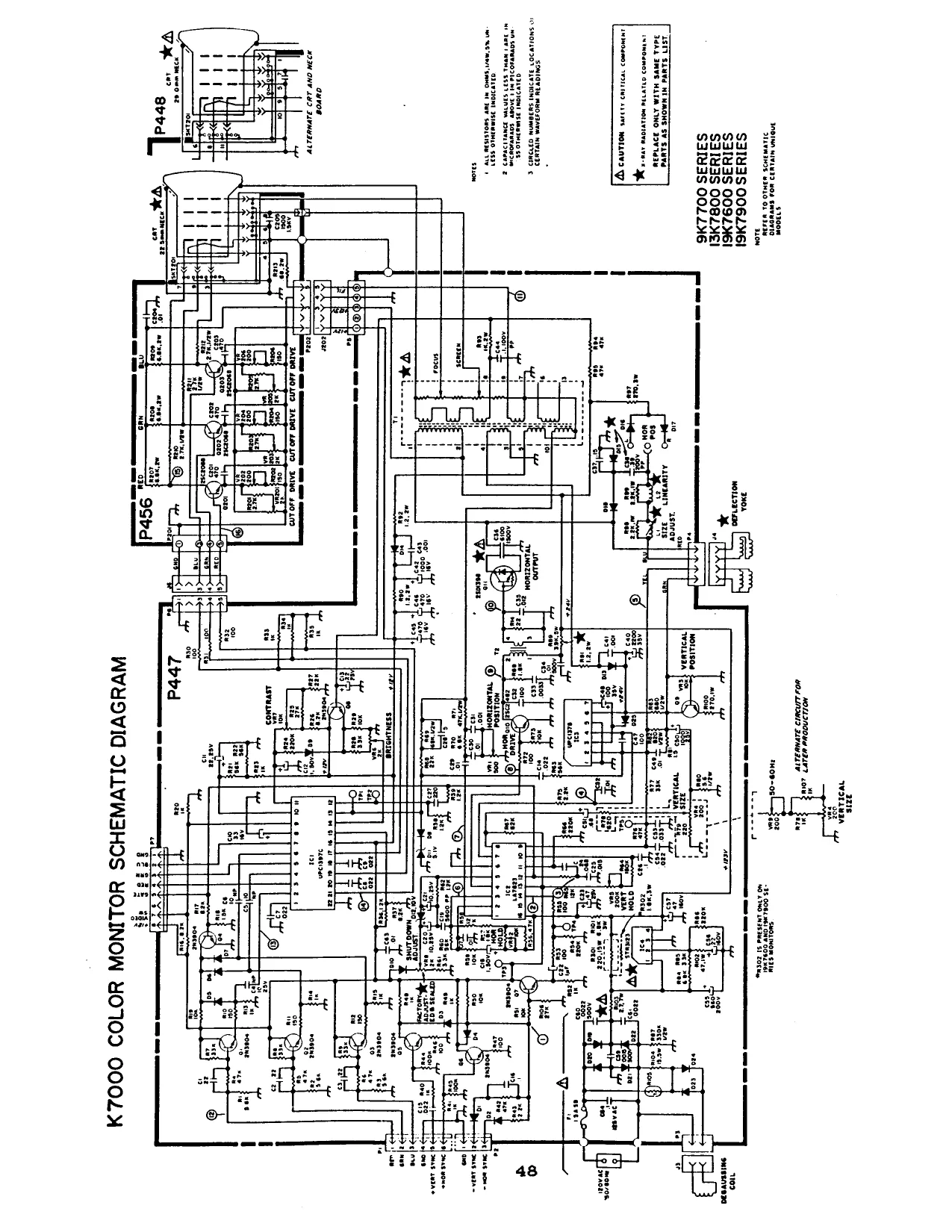
This page is a drawing, shown as the original scan.
- WIRING DIAGRAM
a. Control Panel................ OT
b. Main Harness..... nS
c. Power Supply.......... oe eweeaee Peewee nee ccbievene eee SZ
Page 49
OTTER EEL EY a
i
The left player side connects to CN-7 on the DE-0269 PCB, and the right player side connects to CN-6.
DE-8269-1 PCB
Main Harness
2 STAT ccsetee of ah 25 5 BEERS ER SESSE CREE EEE EEEEEORE -felsfofo} (If) Elsie efofo} [-]s) [-[s]o]<}]e] aes TD a
« 12v “uM _isttdt et oa eg midi seer qr “Hoses TU TT
SOOO eT a
comonena ‘Solder
- = 18 awg wire, all other 22 awg.
Page 51
Page S52
WARNING
Federal law provides severe civil and criminal penalties for the unauthorized reproduction, distribution, or exhibition of copyrighted audiovisual works and video games.
The Federal Bureau of Investigation
investigates allegations of criminal copyright infringement.