Tank TM-010 (Atari) Kiosk Operation and Service
Tank/Tank Cocktail (Atari/Kee, 1974) · Technical Manual · 24 pages · 13 sections · original scan
This page carries no recoverable text. It is a drawing or a photograph. See the original scan.
OSS
lf the products descrit b
WARRANTY
anship | under normal use and service { i thirty
(30) days from date of shipment. None of the Seller's ‘other products
ie or pa rts thereof are’ warranted.
nee it Buyer ring said warranty period, prowes that said iat are @ detective,
- Such proc
are returned prepaid to Sellers’ polane and
__{e) Seller's examination of said products discloses to Seller's lleged defects existed and were not caused by #, ose ; peglect alteration, improper repair, installation or
: This documents is and contains Sonndentntesde secret information of Atari, Inc. his document is. pened under Fonidenta cg for the sole
: tay not be used ie or
: whatever, and remains
TM-010
ATARI
TANK
Operation and Service Manual
ATARI INC 14600 WINCHESTER BOULEVARD, LOS GATOS, CALIFORNIA 95030 » TELEPHONE (408) 374-2440 + TELEX 357-488
This page carries no recoverable text. It is a drawing or a photograph. See the original scan.
The motorola TV and Tank Circuit Boards have been designed to give you, the customer, the most trouble free unit possible. The circuits used are al] solid state for long life and reliability.
Our games are designed with the customer in mind and we appreciate any and all comments from the field.
In the event your unit does require servicing, this manual will aid your efforts.
This manual consists of the following sections:
I. Adjustments
II. Diagnosis and Procedures
III. Warranty and Service
IV. Schematics
ADJUSTMENTS
There are two types of adjustments that can be made to your unit: TV & Circuit Boards.
The controls on the TV Monitor work as in any normal TV. Vertical Hold, Brightness, Contrast & Horizontal Hold. These are located on the back side of the monitor chassis. The vertical & horizontal hold controls should be set in the middle of their range. Turn control until picture tears or rolls, turn control back until picture tears or rolls in the opposite direction & then reset control to the middle of the stable range. The brightness & contrast should be set at a point where the mine field in the center of the playfield is clearly visible.
Circuit Board On Circuit Board I, (which is on the left side of the cabinet, looking from the rear of the same) there are three (3) adjustments you may want to make.
Master Volume: These adjustments are located in the upper right area of the board. There is a small tab on each of these pots & when they are set at the same point the volume between the two tanks will be even.
Missile Firing & Explosion Sound: These adjustments are located in the upper left area of the board. Again there are two (2) pots to adjust. Setting the tabs evenly on the pots will set the volume evenly between the two tanks.
Il. Game Time: There is one (1) switch located on Board I and next to this swtich is the pot which adjusts the game time. This pot has been preset at the factory so that with the switch in the 25¢ position, one game is available for a quarter and will last for 60 seconds. With the switch in the 50¢ position, one game is available for two (2) quarters and will last for 120 seconds. You may set this switch as you wish and also adjust t': time pot to your convenience.
Do not attempt to adjust any other pots located on these boards as they are factory adjustments and tampering with them may have detrimental effects upon the game.
DIAGNOSIS
SYMPTOM CHECK
No Picture Fuse, Power Cord, Harness Connections
No Sound Speaker Connections, Volume Adjustments
Rolling or Tearing Picture Re-Adjust TV Controls
Game Will Not Start Coin Mechanism, Harness Connections
No Tank Movement *Joystick Switches (proper alignment), Harness Connections
No Firing of Shell *Joystick Switches, Harness Connections
*These are simple on/off switches and may be checked with an ohmeter or continuity tester.
NORMAL GAME OPERATION
Inserting the coins immediately starts the game with one Tank in the upper left area of the playfield and the other Tank in the lower right area.
To move Tank forward, push both joysticks forward. To stop Tank, pull both joysticks back. For turning to the right, pull right joystick back and push left joystick forward.
To turn left, push right joystick forward and pull left joystick back. Silkscreened into the front panel are illustrated instructions for the different motions.
To fire the shells, push the red button on the right joystick down. One point is scored each time a shell hits the other Tank. If a Tank hits a mine, the opponent gains one point and the mine will dissappear for the remainder of that game. When a Tank is hit by a shell or encounters a mine, an explosion sound is heard and the Tank flashes. Until this flashing has stopped, his opponent cannot fire another shell. Approximately 20 seconds before the game ends, the score display will begin flashing and continue until the game ends.
TV_TROUBLESHOOTING
NO POWER: Check for blown fuses and proper line voltage. Also check to see if the interlock switch is in the on position, either with the rear door closed or with the switch defeated.
NO PICTURE: Check the monitor fuses. If blown, visually check the monitor for shorts. If fuses are OK, look to see if the CRT's choke filament is glowing and if there are any loose wires.
WHITE PICTURE BUT NO DISPLAY: This symptom indicates two problems. Either the PC Board or the TY is malfunctioning. To double check and make certain of the area of trouble, check the PC Boards that making sure power is reaching them and check the edge connectors making sure they are positioned correctly on the PC Boards. Also check the twelve (12) pin Molex connector on the TV making sure it is correctly connected.
WAVY PICTURE: If this condition exists, check the following two items to be sure they are functioning properly. First check the five (5) volt power supply on the two main circuit boards. This can be done by measuring between the two heavy traces on each board with a voltmeter or an oscilliscope. There should be 5+ 1/4 volts on each board. Next, locate pin 32 on the large monitor circuit board. Measure the voltage from this pin to ground. There should be seventy-three (73) volts at this point. If the voltage is either too high or too low, adjust the 73 volt regulator pot located on the same PC Board in the upper left hand corner. DO NOT TURN THIS POT THRU THE WHOLE RANGE.
Damage will occur to it's associated parts. All that needs to be done is a slight turn to adjust properly.
IMPROPER DISPLAY: Recheck all picture adjustments (brightness, contrast, and etc.) to make sure they are correct.
REMOVAL & REPLACEMENT PROCEDURES
CONTROL PANEL: To achieve easy access to the joystick controls, open the front coin door and remove the two wing nuts mounting the control panel to the cabinet. There is one wing nut on each side. Slide the control panel out far enough to clear the mounting bolts from the cabinet and turn the panel upside down. Set the face of the panel down on the supporting blocks. The joystick controls are now exposed for servicing.
PLEXIGLASS REMOVAL: To remove the plexiglass, open the front coin door and remove the three wing nuts running along the upper frame member of the control panel. Pull the lower aluminum plexiglass anchoring bracket away from the game. The plexiglass should be pushed down and pulled out to remove it from the game.
TV MONITOR REMOVAL: To remove monitor for replacement or repair, first remove plexiglass by following the above Plexiglass removal instructions. Also, remove the four screws mounting the plastic bezel. Loosen the two wing nuts by the corners of the CRT by way of the back door. Remove the 10 Pin Molex connector from the back side of the TV. By inserting a finger into the two holes on each side of the CRT, the monitor can be pulled out.
TV MONITOR REPLACEMENT: To replace the TV monitor, follow in reverse order the steps for monitor removal.
MOTOROLA MONITOR PC BOARD REMOVAL
POWER, AUDIO PC BOARD: To remove this PC Board, simply locate it on the left side of the monitor in back of the power transformer. Carefully pull up on the board. To replace this board, locate the slot between Pins 3 & 4 and put this on your left side, then simply insert into into the edge connector.
MONITOR PC BOARD: To remove the monitor PC Board, take a screwdriver or a similiar object and slowly pry the PC Board up off of the chassis until it clears the pins. Next, unplug the socket from the yoke and slide board out. To replace this board, follow the above steps in reverse order.
MAIN CIRCUIT BOARDS I & II
REMOVAL: Each board is mounted to the cabinet by two screws located one on each side. Remove the edge connectors first, then remove the four screws. DO NOT TRY TO SEPERATE THE TWO BOARDS. Each set of boards must remain as one unit. After removing boards, carefully follow board shipping procedure in order to reduce the chances of damage to a minimum.
REPLACEMENT: Follow the reverse steps of the removal procedures to replace the PC Boards.
PC_BOARD SHIPPING PROCEDURES
When packaging PC Boards for shipment, make sure the top of each board is facing each other with either bubble wrap or foam rubber them. This interfacing Must be thick enough to insure that parts of one board do not come in contact with the other board. DO NOT use small pieces of styrofoam as packing material between the boards. Careful packing is recommended as KEE GAMES, INC. cannot be liable for boards damaged in transit. Also, include a short statement describing the basic problem with the boards.
CABINET MAINT INANCE
Cleaning of the cabinet and plexiglass may be done with any non-abrasive household cleaner. The coin acceptors and lock cylinders should be lubricated periodically with any light oil or silicon aresol spray.
ACCESS DOORS
COIN DOOR: There are two coin mechs in each game. The extra coin mech is there for customer convenience and also as a spare in case of a coin jam in one of the mechs. The coin door provides access to the coin box and to all wing nuts used to secure the monitor, control panel and the bracket for the plexiglass CRT screen.
REAR DOOR: The rear door allows access to the Tank PC Board set, the fuse line filter and transformer assy, Motorola monitor controls and PC Board, and the wing nuts securing the control panel, plexiglass and TV monitor.
J-3 SND LO-AC LO -Ac HI- AC HI= AC GND GND G/aLKk AC-POWER vov/eonz
FUSE DK/G ele) =ND. GND ANALOG, GND
| ANT +5V Coin 2-NChit SY Vv i —[afol[s lo] o[r]a] of o COIN 2-NGI12 ICOIN | —NGJI3 COIN | -NO|i4 BLK = 12v AUCIO-2 AUDIO- |
- ULL GND
sPEARERG al a ee ed fo} RL.D.US
w/e RR.OJS w/BRN g RLUJS
w/R RRUJS
wy
- L.L.0.uS
WG 16 |L.R.O.JS. WIBLUT 71 L U.S Why figit UWS wiv ligik. BUTTON BLK/ W420], BUTTON
ws =o 2 6s 8 al AC POWER -110V/eHz 3s 9s ts ed TV CONNECTOR BNW 57 viDEO Glew 27 GND 80-7
EDGE
CONNECTOR
- PN coin. mecHs A #2,
J | poe ND) |noo RTDHINGOO! COIN- COUNTER |FLUORE SCENTuweho STARTE®
TANK HARNESS
IB2074] ELI fReve
K5T-ELECTRIC DWG
#10: 3)
f-l-l-l-l- SBOE 003492
ou
WAS MOL HEL aot
° of, Step NY \ rs ic TET © paws rt
VAL VBI VEL yO a@ Ded : ° e
slelsle do bleble de [slelsle de poser rR) |iomecon| Lanece te] Theep Ac relSF Tol, ae ref kar c2 yc(tel a eae TT ale este EL ele eat yp at ima n x i y
1 OM 182 163 10% 9) eno Oot
szvi 1% oF Seu 3)
This page reads as a drawing: its text was drawn rather than typeset, and comes out in fragments. See the original scan.
This page reads as a drawing: its text was drawn rather than typeset, and comes out in fragments. See the original scan.
REVSIONS ‘)
PPLY
et
a
« 17) & $48,7, ION IZ ey [| en srenee
s re +e [lessee
sad c102 mEy ae? 4 fe Oy BO AUDIe our 2 wana 254
$
B
a,
aso 33 ae P ev war gomme Toe om — ince ito wnever Bren
- aan ene A [ mcrae ———] ™ SCHEMATIC, mem) TANK BOARD I
——+— Y Bl oose Ty reat seat I [ree 2y 3 2 | 1
AINFS VINFO
ty
NORTEK (28-ri) Romi= HID
3 TANK
22 Mine
Mev STATS py alee Bo) (a MINE eae) MATRIX
MING FIELD FIRE) —
F ADED PLAYFICLD WADE! Feet
m —2I a
12 gg 8. Ace — Wi rey co eye C24 acon 123
ou 254 yy +—-} -—vioeo. ouT
WoL
GOL us acount Loe,
Eva] Se seerios ERT Pee. EUS 1007 ed ola REV PER BCU Wee Py 4 [REV PER ECN 1039) /eshe
ate
daw” poy fos ‘uelvaz ager vez ATTRACT.
Boom CON
Jt fad VOL any
4 10M @ag Ww
o28
ue
KEE GAMES. INC. 20 MATHEW ST SANTA CLARA. CALE 95050 9.60 408) 24
TANK BOARDIL REV H
Une 7a i ROM MOXING, PLAYFIELD )MIMFILLD ,* INL
SON
This page reads as a drawing: its text was drawn rather than typeset, and comes out in fragments. See the original scan.
‘ATTRACT BOUNCE Z,
PLAYER e113 0M THE TIGHT SIDE. (WHITE) PLANER #2. 15 ON THE teer S08: (peqc )
Sosy STRRT #2 musi Bae
i ee: , owed aye tear P oT Dow Je tye | ure To et
ob, : ad " sos Slee
TANK 2, PLANFIELD 2 source aap oe BOUNCEI
CAOKSS, IN 330 MATHEW st SANTA CLAXA. CALF. 95050 1408) 249-6090
TANK BOARDIT | Zev A =r aT Via me i gn Te se SYNC, TIMING £ LOWTESL Chk aS
OOR1IZ PRE DOF 2
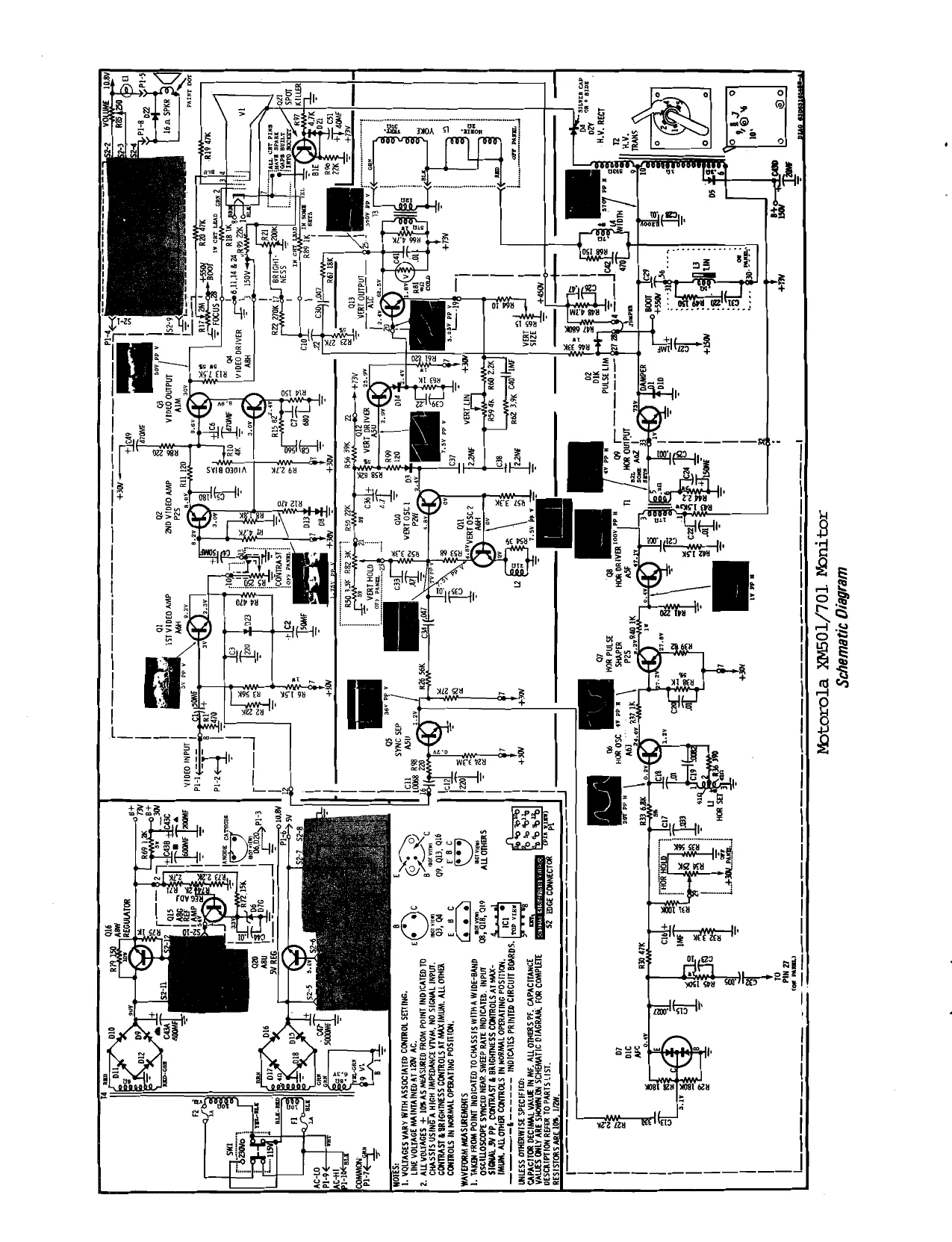
This page is a drawing, shown as the original scan.
This page carries no recoverable text. It is a drawing or a photograph. See the original scan.
ATARI"INC 14600 WINCHESTER BOULEVARD, LOS GATOS, CALIFORNIA 95030 + TELEPHONE (408) 374-2440 - TELEX 357-488