Battlezone DP-156-3rd-01A
Battlezone (rev 2) (Atari, 1980) · Drawing Package · 1 pages · original scan
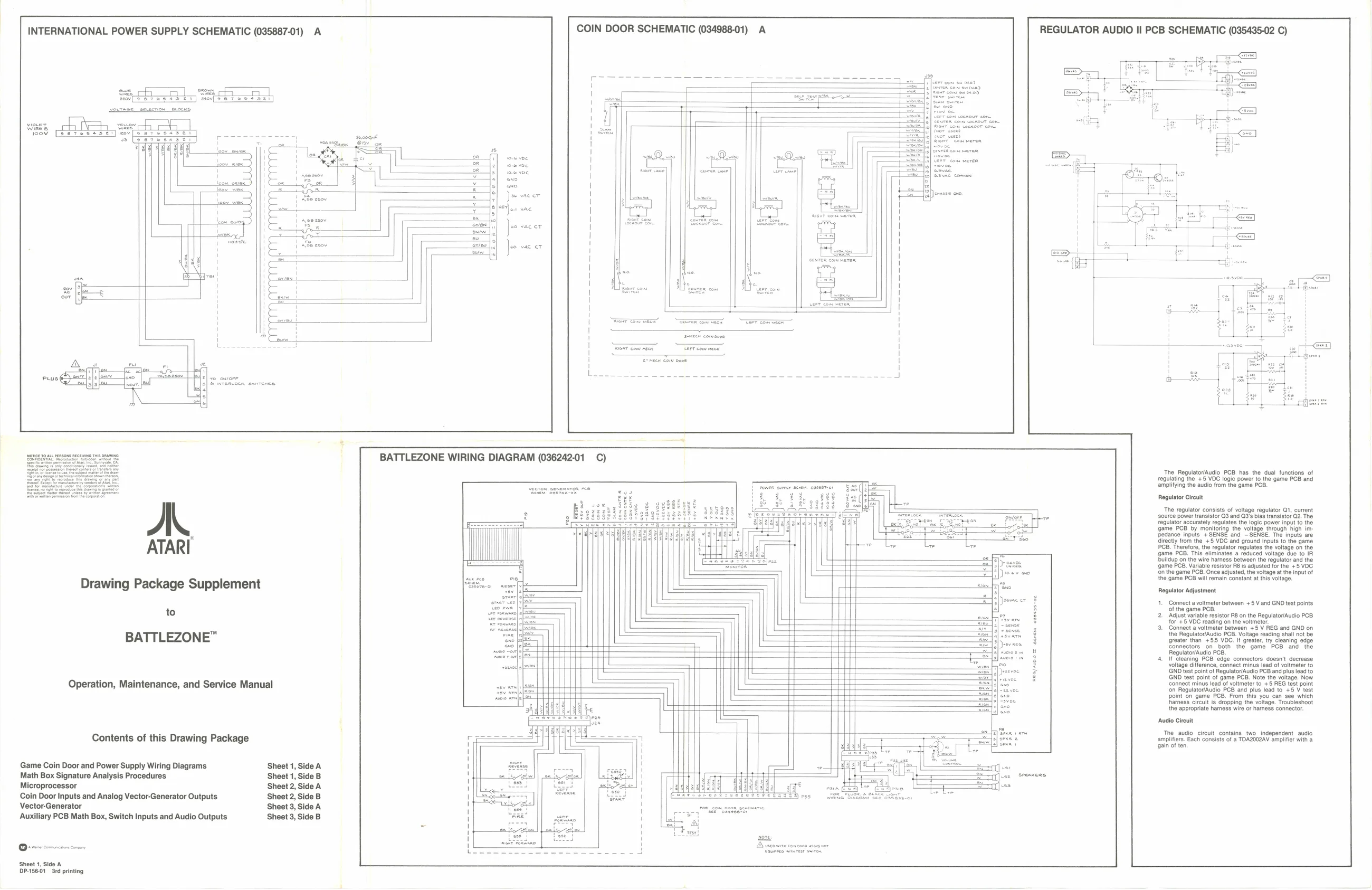
COIN DOOR SCHEMATIC (034988-01) A REGULATOR AUDIO Il PCB SCHEMATIC (035435-02 C)
INTERNATIONAL POWER SUPPLY SCHEMATIC (035887-01) A
eecoaut
8/88
emerge erence mare BATTLEZONE WIRING DIAGRAM (03624201 C) ‘The. RegulatorAudlo PCB has, the dual functions of
regulating the +5 VOC logic power to the game PCI
amplifying the audio from the game PCB, Regulator Circuit
‘The regulator consists of voltage regulator Qt, current
source power transistor Q3 an
regulator accurately regulates game PCB by monitoring the votepe through high me edance inputs +SENSE and ~SENSE. The inputs are directly from the +5 VDC and ground inputs to the game PCB. Therefore, the regulator regulates the voltage on the game PCB. This eliminates a reduced voltage due to IR. Dulldup on the wire harness between the regulator and the ‘game PCB. Variable resistor RB is adjusted for the +5 VDC. fon the game PCB. Once adjusted, he voltage at the input of. the game PCB will remain constant at this voltage.
Drawing Package Supplement coe
Regulator Adjustment
1. Connect a voltmeter between +5 V and GND test points
of the game PCB. 2 Adjust variable resistor RB onthe RegultoiAudio POB for +5 VDC reading on the voltmeter. a. Connect a vlimetsr between +8 V REG and GND on the Regulator/Audio PCB. Voltage reading shall not be ‘greater than +55 VOC. If greater, try cleaning edge Connectors on both the game PCB and the Regulator/Audio PCB, to
BATTLEZONE™
doesn't decrease ad of voltmeter to GND test point of Regulator/Audio PCB and plus lead to GND test point of game PCB. Note the voltage. Now connect minus lead of voltmeter to +5 REG test point REG/aoo T senem ossess-ce
Operation, Maintenance, and Service Manual soy rn fesse ‘on Regulator/Audio PCB and plus lead to +5 V test ce ws S point on game PCB. From this you can see which me ee harness circuit is dropping the voltage. Troubleshoot ad! the appropriate hamess wie of hamess connector. it Ep Audio Circuit
The audio circuit contains two independent audio amplifies. Each consists of a TDAZ002AV amplifier with a q Contents of this Drawing Package ——— E gun often
Game Coin Door and Power Supply Wiring Diagrams Sheet 1, Side A
| Math Box Signature Analysis Procedures | Sheet 1, Side B | 4 | Ie | ||
| Microprocessor | Sheet 2, Side A | PEE | CECEEEE, | ||
| Coin Door Inputs and Analog Vector-Generator Outputs | Sheet 2, Side B | | | | Coste | en eee | vecevere |
| Vector-Generator | Sheet 3, Side A | J] | rensapm,geas seem | ||
| Auxiliary PCB Math Box, Switch Inputs and Audio Outputs | Sheet 3, Side B | Li“ |
~ {res
Sheet 1, Side DP-156.01 3rd printing