Asteroids DP-143-7th-01A
Asteroids (rev 4) (Atari, 1979) · Drawing Package · 1 pages · original scan
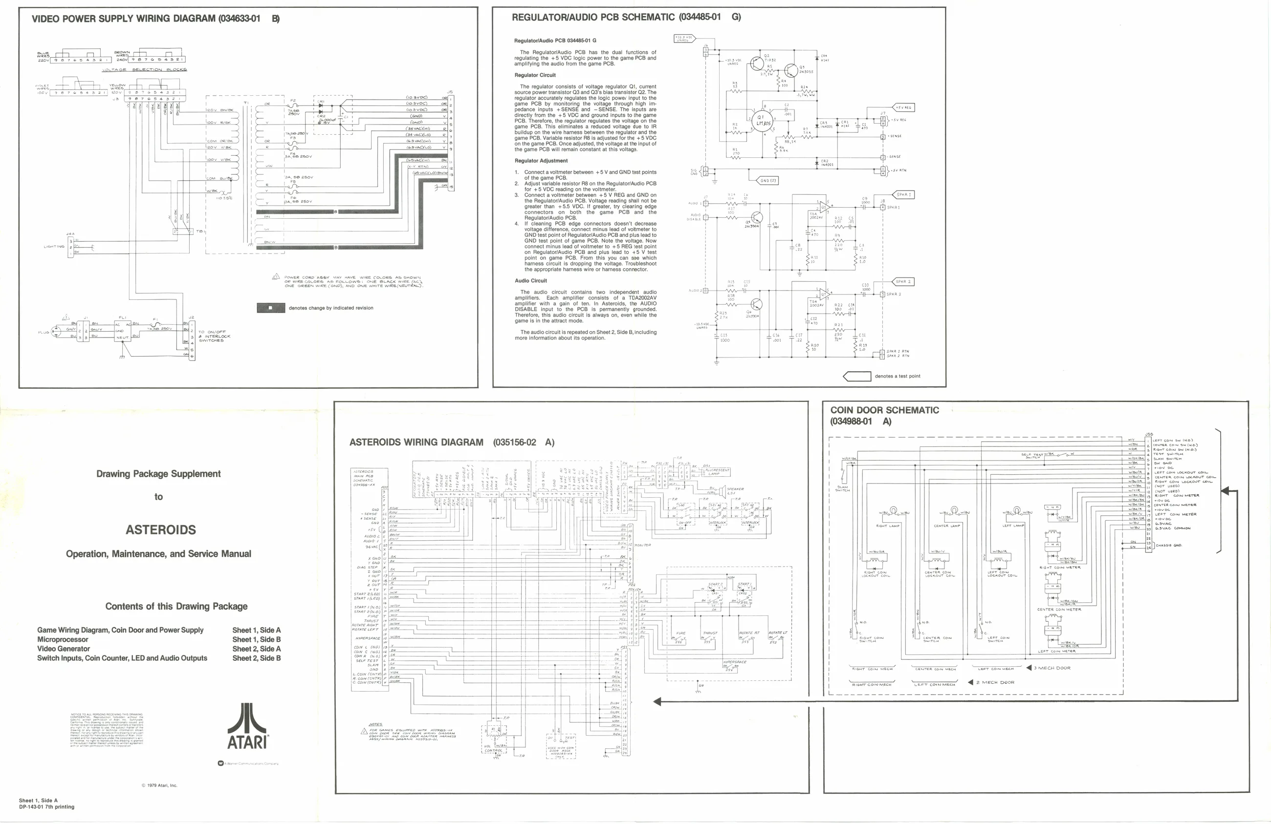
VIDEO POWER SUPPLY WIRING DIAGRAM (034633-01 _B) REGULATORIAUDIO PCB SCHEMATIC (034485-01 G)
Rogulator/Audio PCB 03448501 G
‘The Regulator/Audio PCB has the dual functions of regulating the +5 VDC logic power to the game PCB and amplifying the audio from the game PCB.
Regulator Circuit
‘The regulator consists of voltage regulator Qi, current
source power transistor G3 and O3's bias transistor O2. The
regulator accurately regulates the logic power input to the game PCB by monitoring the voltage through high imedance Inputs +SENSE and SENSE. The inputs are
Girety from the, +8 VOC and ground inputs to the game
Cons PCB. Therefore, the regulator regulates the voltage on the
J Caswneknd, game PCB. This eliminates a reduced voltage due to IR eee Dulldup on the wire harness between the regulator and the gan PCB. Variable resistor Fi adjusted for the +8 VOC
‘on the game PCB. Once adjusted, the voltage atthe input of
the game PCB willtomain Sonetant at tis voltage Regulator Adjustment
1. Connect a voltmeter between +5 V and GND test points +5 VDC reading on the voltmeter
Of the game PCB. 2 Adjust variable resistor RB on the Reguatovudlo PCB +5 VDC reading on the voltmeter.
- Connect a walimele between 8 REG ané GND on the Regulator/Audio PCB. Voltage reading shall not be ‘greater than +55 VOC. It greater, try clearing edge connectors on both the game PCB and the Regulator/Augio PCB.
- If cleaning PCB edge connectors doesn't decrease voltage difference, connect minus lead of voltmeter to ‘GND test point of Regulator/Audio PCB and plus lead to GND test point of game PCB. Note the voltage. Now connect minus lead of voltmeter to +5 REG test point ‘on Regulator/Audio PCB and plus lead to +5 V test
point on game PCB. From this you can 26 which
harness circuit is dropping the voltage. Troubleshoot the appropriate hamess wire or harness connector. QS Pewee CORD ABO MAY HAVE WIRE COLORS AD SHOWN Gre Sreean mice Cond), AO Owe wire mame NETO,
TRI ies craoe ty nto vison ‘Audio Circuit CE
The audio circuit contains two independent audio ‘amplifiers. Each amplifier consists of a TOAZOG2AV ‘amplifier with a gain of ten. In Asteroids, the AUDIO DISABLE input to the PCB is. permanentiy grounded. Therefore, this audio circuit Is always on, even while the game i in the attract mode.
‘The audio circuit is repeated on Sheet 2, Side B, including ‘more information about its operation.
7 eens tt pt
COIN DOOR SCHEMATIC
ASTEROIDS WIRING DIAGRAM (035156-02 A)
Drawing Package Supplement
to
ASTEROIDS
Operation, Maintenance, and Service Manual
iran 1ae0) Contents of this Drawing Package sranr seo |s
Game Wiring Diagram, Coin Door and Power Supply Sheet 1, Side A peter | — ‘ I! ; fwre ar mmeer Microprocessor Sheet 1, Side B anmanamace — fhe 7 5 Video Generator Sheet 2, Side A ‘Switch Inputs, Coin Counter, LED and Audio Outputs Sheet 2, Side B TEE 9 _ GREK eee Ter cemmaer—~ <> mech coon ener commen” “Terrcommecy’ — @ 2 mech poor
an
(© 1970 Ata, ne.
Shoot 1, Side A DP-149.01 7th printing