Crossbow Version.2.0
Crossbow (version 2.0) (Exidy, 1983) · Manual · 58 pages · 22 sections · original scan
This page carries no recoverable text. It is a drawing or a photograph. See the original scan.
OPERATOR'S AnD
SERVICE mANUAL
©1983 Exidy, Inc. 390 Java Drive, Sunnyvale,California 94089-1271 Telephone: (408) 734-9410 Toll-free: (800) 538-8402 Telex: 357-499 (EXIDY MNTV)
This page carries no recoverable text. It is a drawing or a photograph. See the original scan.
PROPRIETARY NOTICE
The contents of this manual are the property of EXIDY, INC. not to be copied or reproduced in any manner whatsoever, nor disseminated in any form to any person who is not a Crossbow user without the permission of EXIDY.
Copyright ©1983 by EXIDY, INC.
————— a
COPYRIGHT
Copyright ©1983 by EXIDY, INC. All rights reserved. No part of this publication may be reproduced, transmitted, transcribed, stored in a retrieval system, or translated into any language in any form, or by any means without the prior written permission of EXIDY, INC. 390 Java Drive, Sunnyvale, California 94089.
DISCLAIMER
EXIDY, INC. makes no representations or warranties with respect to the contents hereof and specifically disclaims any implied warranties of merchantability or fitness for any particular purpose. Further, Exidy, Inc. reserves the right to revise this publication from time to time in the content hereof without obligation of Exidy, Inc. to notify any person of such revision or changes.
TRADEMARKS
Crossbow™ is a trademark of Exidy, Inc.
This equipment generates, uses and can radiate radio frequency energy and if not installed and used in accordance with the instruction manual, may cause interference to radio communications. It has been tested and found to comply with the limits for a Class A com-
puting device pursuant to Subpart J of Part 15 of FCC
Rules which are designed to provide reasonable protection against such interference when operated in a commerical environment. Operation of this equip-
ment in a residential area is likely to cause interference
in which case the user at his own expense will be required to take whatever measure may be required to correct the interference.
QUESTIONS
EXIDY encourages technicians to use the toll-free customer service hotline for any questions they may have regarding Crossbow™. That number is (800) 538-8402.
a S————sSsSsa—aa_——>oowmwm oo
FOREWORD
PART ONE: Contains Preliminary Procedures, describing game inspection, installation, and chekcout.
PART TWO: Adjustment procedures are given for Power Supply, Audio Volume, Selectable Options, Gun Sight Alignment and Optical Sensitivity Adjustment.
PART THREE: Modes of Operation, describes the four CROSSBOW™ modes: Automatic Self- Diagnostic Test Mode, Manual Diagnostic Mode, Attract Mode, and Game Play Mode.
PART FOUR: Contains the Electrical Schematics.
PART FIVE: Contains the Mechanical and the Electronic Part Breakdown.
This page carries no recoverable text. It is a drawing or a photograph. See the original scan.
TABLE OF CONTENTS
I, PRELIMINARY PROCEDURE . GAME INSPECTION .. . VISUAL INSPECTION . FILING A CLAIM ... . INSTALLATION .. . MAJOR COMPONENTS . . GUN STOCK INSTALLATION . PRELIMINARY CHECKOUT PROCEDURE,
Il. ADJUSTMENTS
- POWER SUPPLY INFORMATION AND ADSST MENTS
- AUDIO BOARD ADJUSTMENT ...
- OPERATOR SELECTABLE OPTIONS a. Coinage b. Starting Number of Friends ... c. Game Play Difficulty
- OPTICAL SENSITIVITY ADJUSTME!
- GUN SIGHT ALIGNMENT
III. MODES OF OPERATION 1, AUTOMATIC SELF-DIAGNOSTIC TEST MODE ..
- MANUAL DIAGNOSTIC MODE
- THE ATTRACT MODE
- GAME PLAY MODE
Iv. SCHEMATICS . WIRING DIAGRAM . . LOGIC PCB ... . AUDIO PCB . . OPTICAL PCB . POWER SUPPLIES .
Vv. PARTS LIST . MECHANICAL . LOGIC PCB . . AUDIO PCB . POWER SUPPLY .. . OPTICAL PCB ..
LIST OF ILLUSTRATIONS
- Major Component Locations
WON AWAWL a. PCB Assembly Locations . .
- Rear Access Panel
» Crossbow™ Stock .. . Gun Sight Alignment
- Power Supply and Volume Adjustment . Gun Stock . Optical Adjustment . Gun Sight Alignment . EPROM and RAM Error Code Locations . Play Select . Wiring Diagram . Gun Assembly
- Logic PCB . Audio PCB
- Power Supply . Optical PCB
Preliminary
Procedure
N
PRELIMINARY PROCEDURE
GAME INSPECTION
All Exidy equipment is carefully packaged in well-padded cardboard containers to prevent damage during shipment. Before signing the delivery receipt, you should follow this procedure:
- Check for obvious damage and make certain that the physical piece count of the shipment maiches the piece count on the bill of lading. These two procedures should always be done before signing the delivery receipt.
- Shortages and/or obvious damage to the packaging on any given shipment should be noted in writing on the delivery receipt before signing for the delivery.
- If concealed damage is suspected on any shipment, those packages believed to contain the damaged goods should be opened in the presence of the delivery driver. If the goods have sustained concealed damage, a description of said damage should be noted in writing on the delivery receipt before signing for the delivery.
- Never apply power to any game with noticeable damage.
VISUAL INSPECTION
- Remove the rear and front access doors with the appropriate packaged key.
- Examine each major and electrical component thoroughly for scrapes, dents, broken or missing parts and loosening screws.
- Check for loose cable connectors.
- Visually verify that all the integrated circuit devices (IC’s) plugged into sockets are properly seated and that no IC pins are bent or misaligned. If you find any damage during this inspection, file a claim with the carrier. Send a complete report of the damage to Exidy Inc.
FILING A CLAIM
TO FILE A CLAIM, FOLLOW THIS PROCEDURE:
- Any and all damaged freight, including packaging, should be retained by the consignee until a physical inspection of said freight can be made by a representative of the carrier involved.
- The Claims Manager for the carrier involved should be notified as soon as possible after the damaged goods are received. Preferably, the carrier’s Claims Manager should be notified within forty-eight (48) hours of receipt of the goods by the consignee. 1f warranted, a written claim must be filed with the carrier(s) involved. A detailed description of the damage(s) must be provided including copies of delivery receipt and/or bill of lading, inspection report and invoice. The carrier(s) to which a claim has been filed against is required by law to respond to within thirty (30) days after receiving your claim and must reach a final disposition in the matter within one hundred twenty (120) days.
QUESTIONS
Exidy encourages technicians to use the toll-free customer service hotline for any questions they may have regarding CROSSBOW™. That number is (800) 538-8402.
INSTALLATION
Planning the location of the game should involve both physical and electrical considerations. Such physical considerations concern the placement of the equipment with respect to these clearances:
@ HEIGHT: 80.00 inches, 203.2 cm. @ WEIGHT: 25.25 inches, 65.1 cm. @ DEPTH: 35.00 inches, 88.9 cm.
An indoor, relatively dust-free environment is necessary, with proper conditions required of any electrical component. Electrical considerations include availability of an AC outlet with the correct voltage and frequency. You should consider the working space required for technicians and operators including access to the rear of the game.
MAJOR COMPONENTS
The Crossbow™ game is a colorfully illustrated upright video game with high resolution graphics. A more detailed game play is located in the Game Description chapter of this manual. The major components of your Crossbow game are illustrated in (See Fig. 1). These major components are the following: © Crossbow™ Gun . © Coin Mechanism © Monitor Chassis @ Power Supply Chassis . © Control Panel @ All PCB Assemblies © Speakers The PCB assemblies are listed as follows:
@ Game Logic PCB @ Power Supply PCB @ Audio PCB @ Photo Optic PCB
MONITOR —
SUPPLY
GUN STOCK INSTALLATION
MECHANICAL
Gun Stock is detached from the forestock for shipping. To install Crossbow™ gun stock, proceed as follows:
- Locate the 3 mounting screws, packed inside shipping carton with Crossbow Gun.
- Loosen the 8/32 set screw in the FORESTOCK that secures down the OPTICAL TUBE ASSEMBLY.
- Check that the gun optic PCB connector is in place. -
- Gently place gun stock onto forestock mount with the (2) 10x24x1 button head screws, and
- 1/4x20x3/8 cap screws and secure gun stock to forestock (See Fig. 2).
Be sure to tighten down the set screw in FORESTOCK that secures the OPTICAL TUBE ASSEMBLY.
CROSSBOW STC
BUTTON HEAD SCREWS (10x24x5/8)
FORESTOCK ———
832 SET SCREW INS
(
»
: (1/4x20x3/8)
PRELIMINARY CHECK PROCEDURE
AFTER PROPERLY INSTALLING THE STOCK PROCEED AS FOLLOWS:
1, Connect the power plug into 110 VAC 60 Hz outlet.
- Three seconds after power-up there should be a burst of sound followed by the AUTO SELF DIAGNOSTIC TEST.
- Following the AUTO SELF DIAGNOSTIC TEST the game will enter the ATTRACT MODE.
4, When AUTO SELF TESTS are completed and the gun stock is properly installed proceed with the GUN SIGHT ALIGNMENT.
GUN SIGHT ALIGNMENT
- Open the Coin Door to access the AC interlock switch, game will power down.
- While holding down the START BU’ TON pull
GUN SIGHT —~
FIG. 3 GUNS out the interlock switch to restore power. After a burst of sound the screen should display the MANUAL DIAGNOSTIC MENU MODE.
. Be sure the index is pointing to GUN SIGHT ALIGNMENT, use the Start Button to index if not.
. Pull gun trigger and a crosshair (+) will be displayed, release gun trigger.
. Aim the gun sight to center of crosshair, pull gun trigger once and gun sight will be aligned to the last burst.
. Press down the START BUTTON and return to the MANUAL DIAGNOSTIC MENU. With the START BUTTON move the index to EXIT MODE, press the GUN TRIGGER and return to the ATTRACT MODE.
GUN BURST wa
xsHT ALIGNMENT
"|
This page carries no recoverable text. It is a drawing or a photograph. See the original scan.
This page carries no recoverable text. It is a drawing or a photograph. See the original scan.
ADJUSTMENTS
- POWER SUPPLY INFORMATION AND ADJUSTMENTS ALL DC Power required to operate Crossbow™ is supplied by the Exidy Power Supply Module. These supply outputs are as follows: OtBV ee. ....@ 9 AMPS . OHIBV ee @ 8 AMPS © -18V ee @ 8 AMPS
Oca AND CREDIT OPTIONS TCH OPTIONS SWITCH \
SWITCH-1
4 ADJUSTMENT LOCATIONS
Il. AUDIO BOARD ADJUSTMENTS Adjust R15 master audio volume control located at position T2 on the Audio Logic Board (See Fig. 4) and adjust audio level while game is in progress. This audio board rides piggyback on the logic board, mounted inside of the cabinet on the side wall (See Fig. 1).
——————————————————————— ey
III. OPERATOR SELECTABLE OPTIONS
Crossbow™ has several selectable switch options controlled by an 8 position DIP SWITCH located at B1 of the AUDIO BOARD and a 4 position DIP SWITCH located at J19 of the LOGIC BOARD. Both switches are accessible through the rear door of the game.
SWITCH OPTION SETTINGS 8 POSITION SWITCH LOCATION B1
@ = FACTORY SETTINGS
COINAGE ewe puree et
| 1COIN —1 CREDIT | OFF | OFF |
@ 2 COINS — 1 CREDIT OFF ON
| 3 COINS — 1 CREDIT | ON | OFF |
| 4 COINS — 1 CREDIT | ON | ON |
| 1COIN — 2 CREDITS | OFF | OFF |
| 2 COINS — 2 CREDITS | OFF | ON |
| 3 COINS — 2 CREDITS | ON | OFF |
| 4 COINS — 2 CREDITS | ON | ON |
| 1COIN — 3 CREDITS | OFF | OFF |
| 2 COINS — 3 CREDITS | OFF | ON |
| 3 COINS — 3 CREDITS | ON | OFF |
| 4 COINS — 3 CREDITS | ON | ON |
| 1 COIN —4 CREDITS | OFF | OFF |
| 2 COINS — 4 CREDITS | OFF | ON |
| 3 COINS — 4 CREDITS | ON | OFF |
| 4 COINS — 4 CREDITS | ON | ON |
SWITCH OPTION SETTINGS 4 POSITION SWITCH LOCATION J19
SWITCH ITCH GAME PLAY DIFFICULTY A “
1 EASY ON
@2 NORMAL 3 HARD 5 MOST DIFFICULT
STARTING CHARACTERS
2 CHARACTERS @ 3 CHARACTERS 4 CHARACTERS 5 CHARACTERS
IV. OPTICAL SENSITIVITY ADJUSTMENT
The Crossbow uses an Optical Sensor PCB to monitor the scanning electron beam of the CRT. Gun positioning information from this Optical Sensor PCB is monitored by the Logic PCB. The Optic PCB sensitivity adjustment allows for monitor intensity, distance between gun and monitor and the electronic circuitry tolerance. During game play each time the trigger is pulled there will be a white flash and a small dot is displayed wherever the gun is aimed. If for any reason the optic circuitry is not sensing the screen when the trigger is pulled the dot will not be displayed, an audio warning sound will be heard. Whenver this occurs, the optical sensor sensitivity should be readjusted.
- To access the optical electronics, remove the (2) button head screws and the (1) cap screw and gently lift the Gun Stock from the Forestock (See Fig. 5).
- Select the MANUAL DIAGNOSTIC MODE. To enter this mode, hold down the Start Button while applying power.
BUTTON HEAD SCREW _ (10x 24x5/8)
FORESTOCK —
SET SCREW 8-32x3;
- Index the pointer to the CHECK INTERRUPTS test, pull gun trigger and execute. When test is complete it will return to the ANUAL DIAG- NOSTIC MENU MODE.
4, Index the pointer to the OPTICAL ADJUST- MENT and pull Gun Trigger, a white screen should appear.
. If the screen should come up with wavering lines, repower the game and return to MANUAL DIAGNOSTIC MENU. Perform the CHECK INTERRUPTS, then index to the OPTICAL AD- JUSTMENT. ou
(continued)
CROSSBOW STOCK
CAP SCREW (1/4 20x3/)
Fig. 5 GUN STOCK
. Aim the Gun to the enter of the screen, an orange rectangular pattern with a brown leading edge should be displayed (See Fig. 6-C). . Turn sensitivity control CCW until oscillation and an orange rectangular pattern are displayed (See Fig. 6-A). Now turn sensitivity control CW until oscillation diminishes just beyond this oscillation point (See Fig..6-B), from this point turn sensitivity control CW approx. 4 turn more. This should be the optimum setting.
=
= = =
= SS
- The rectangular pattern should appear on the screen wherever you aim the Forestock (Optic), with the exception of approx. 2” to the extreme left of screen.
- Reinstall the Gun Stock Assembly. Refer to Crossbow™ Stock Installation procedure (Page 4 Steps 2 & 3). This completes the gun sight and optical check.
6 OPTICAL ALIGNMENT
GUN SIGHT ALIGNMENT
. Open the Coin Door to access the AC interlock switch, game will power down (See Fig. 1). . While holding down the START BUTTON pull out the interlock switch to restore power. After a burst of sound the screen should display the ANUAL DIAGNOSTIC MENU MODE.
. Be sure the index is pointing to GUN SIGHT
GUN SIGHT ALIGNMENT, use the Start Button to index if not.
- Pull Gun Trigger and a crosshair (+) will be displayed, release gun trigger. 5, Aim the Gun Sight to center of crosshair, pull Gun Trigger once and Gun Sight will be aligned to the last burst (See Fig. 7).
a PULSING BURST
7 GUN SIGHT ALIG
"6 ia
Modes Of Operation
This page carries no recoverable text. It is a drawing or a photograph. See the original scan.
MODES OF OPERATION
CROSSBOW™ HAS FOUR MODES OF OPERATION:
A. AUTO SELF DIAGNOSTIC TEST MODE B. MANUAL DIAGNOSTIC MODE : Cc. ATTRACT MODE D. PLAY MODE
To bypass all diagnostics, press crossbow trigger during the power-up sequence.
AUTO SELF DIAGNOSTIC TEST MODE
RAM TEST SCREEN RAM TEST CRC OF PROGRAM ROMS CHECKSUM OF DATA BANK ROMS AUDIO TEST E? PROM
MANUAL DIAGNOSTIC MENU MODE.
To access the manual diagnostic mode, hold down the START BUTTON on ower-up. Once this mode is accessed, any of the listed selections may be indexed by the player start button and executed by the GUN TRIGGER.
GUN ALIGNMENT
Displays a crosshair (+) for gun sight alignment. Aim the GUN SIGHT at center of crosshair and fire gun once. the GUN SIGHT will be aligned to the last burst.
NOTES: Press START BUTTON and return to the MANUAL DIAGNOSTIC MENU.
RAM TEST
Tests RAMS on logic board at locations A8 and Ag*
SCREEN RAM TEST
Tests RAMS on logic board at locations:**
B14-B21 C14-C21 D14-D21 E14-E21
CRC CHECK OF PROGRAM ROMS
Tests OMS on logic board at locations Al, A2, A4, and A6.**
CHECKSUM OF DATA BANK ROMS
Tests ROMS on logic board at locations:*
B1, B3, B4 Cl, G3, C4, C6, C8, C10, C11 D1, D3, D4, D6, D8, D10, D11 El, E3, E4, E6, E8, E10, E11
AUDIO TEST
Tests the communication between logic and audio board.
- See Diagnostic Error Code FIG. 8 for suspected location of RAM or ROM. ** The Processor may not run dependent on the extent of chip failure of these locations.
SS —$=$mmmsmS9 “Tt!
CHECK INTERRUPTS
Tests for horizontal and vertical frame interrupts.
GRAY SCALE
Displays a graduated gray scale for monitor check or adjustments.
CROSSHATCH
Displays horizontal and vertical lines for monitor linearity and convergence checks or adjustments.
COLOR BARS AND BLOCKS
Displays a color visual test pattern utilizing the backround and moving object circuitry. The bars are produced by the backround circuitry and the blocks are produced by the moving object circuitry.
OPTICAL ADJUSTMENTS
Displays a rectangular pattern for adjusting the sensitivity of the Optical Sensing Circuitry. RESET TO FACTORY SETTINGS
Sets the high score and also checks the E? ROM*** located at B11 of the logic board. The E? PROM contains the high score table and gun alignment information. Running this diagnostic will reset the high score table. It will also require that the accuracy of the gun alignment be rechecked.
EXIT
Returns game to the ATTRACT MODE.
FREE PLAY
For those wishing to demonstrate crossbow, a freeplay mode may be achieved by turning on switch # on audio board at location B1.
ATTRACT MODE
The attract mode appears after power-up auto self diagnostic and aftger every game. This mode will continue to display the attract mode repeatedly until a coin, and the start button is pressed.
HIGH SCORE TABLE
DESERT OR VILLAGE GAME SCENE
CROSSBOW™ LOGO WITH COIN AND CREDIT INSTRUCTIONS
CROSSBOW™ GAME PLAY INSTRUCTIONS
#* FE? PROM = Electrically Erasable Programable READ ONLY MEMORY.
This page carries no recoverable text. It is a drawing or a photograph. See the original scan.
PLAY MODE
The attract mode will be displayed ready for play. After sufficient credits are awarded, press the Start Button the screen will now display the game play map, and two or three colored boxes: RED, GREEN and BLUE (Fig. 9). The player selects the game play scene by firing the crossbow at a colored box and choosing the colored path he wishes to challenge. If your party survives this level, the player can by selecting a colored box, continue until this adventure ends when all party members are killed. The player must remember which colored path leads. to each scene’s unique element of danger.
Points are awarded for each target shot and are based on its difficulty to be hit. Bonus points are awarded at the end of each level for each surviving party member. Surviving certain very difficult levels also awards the player with bonus members, increasing the size of his party. Valuable treasures can be found in some scenes. The final goal is the EVIL MASTER. When you have defeated the EVIL MASTER, you again will be bonus points and the game will continue.
SHOOT HERE
Ta FOLLOW GREEN PATH
Fig. 9 PLAY SELECT ~~ ie *
) a : co) “2 ]
This page carries no recoverable text. It is a drawing or a photograph. See the original scan.
( ll to-----4 Lecce ans, ‘Avoio Fig. 10 WIRING DIAGRAM
i a_i red es wt ED = 3 aE 74 301 =] we aia Ate ol pee 1 a ey | EE oe OS BE area TAY LT
a j qi
a att 8 Ei ¥ ill
This page carries no recoverable text. It is a drawing or a photograph. See the original scan.
This page carries no recoverable text. It is a drawing or a photograph. See the original scan.
This page carries no recoverable text. It is a drawing or a photograph. See the original scan.
T wregeces o | mee .,
This page carries no recoverable text. It is a drawing or a photograph. See the original scan.
§ stleldsded
ay
This page carries no recoverable text. It is a drawing or a photograph. See the original scan.
ees
820K aK reese 6 crt [m= [oem =
i a smart, [ico 17. 3] a Tinea wo
Steere 6
PRODUCTION. NOTES:
L JUWER WSTHLED Ye Cane Sense Lame. 2.0, nee 04 # 2NEODS CARLING TON WOW TAANSISTOAS.
AC CONNECTION TABLE
FOR USE ATT nsvac [2zoue | [JuNPeR | 253
‘APPLY AC AT.
FUSE INPUT AT
ausons
+ 5 VOLT REGULATOR SUPPLY
This page is a drawing, shown as the original scan.
Parts List
This page carries no recoverable text. It is a drawing or a photograph. See the original scan.
MECHANICAL PARTS
APPENDIX B: The following is a list of parts with part numbers should you ever need to order replacement parts for your Crossbow™. Replacement parts should be placed through your local Distributor.
PART NUMBER DESCRIPTION
01-0111-00 ASSEMBLY, LOGIC & AUDIO PCB SET
. 98-0006-00 ASSEMBLY, CABINET 74-0001-00 ASSEMBLY, REAR DOOR 65-0131-00 BRACKET, INTERLOCK REAR DOOR 65-0132-00 BRACKET, INTERLOCK COIN DOOR 48-5012-00 SWITCH INTERLOCK 48-3006-60 SWITCH, START BUTTON
95-0018-00 ASSEMBLY, FLUORESCENT FIXTURE 95-0019-00 BULB, FLUORESCENT 15W 95-0030-00 STARTER, FLUORESCENT
95-0017-00 SPEAKER 6 x 9 65-0114-00 GRILL, SPEAKER
70-0001-00 ASSEMBLY, 19” COLOR MONITOR 90-0101-00 ASSEMBLY, BEZEL
90-0096-00 ASSEMBLY, COIN DOOR 95-0036-00 COIN BOX ENCLOSURE 95-0035-00 COIN DOOR 95-0016-00 CASH BOX PLASTIC 95-0015-00 COIN COUNTER
90-0098-00 ASSEMBLY INTERNAL ARTWORK 80-0075-00 INTERNAL ARTWORK RIGHT & LEFT 80-0077-00 INTERNAL ARTWORK TOP 80-0078-00 INTERNAL ARTWORK BOTTOM
80-0081-00 OVERLAY, CONTROL PANEL 80-0080-00 DECAL, LEFT SIDE 80-0079-00 DECAL, RIGHT SIDE
80-0065-00 PLEX, MONITOR 65-0113-00 BRACKET, MONITOR
80-0066-00 PLEX, LOGO 65-0110-00 BRACKET, LOWER > 65-0111-00 BRACKET, UPPER
80-0068-00 MIRROR 65-0113-00 BRACKET, MIRROR 51-2204-00 SCREW, #8 x 1/2 P.H.X.
(continued)
eee
HARNESS
PART NUMBER DESCRIPTION
49-0067-05 49-0066-05 49-0065-05 49-0064-' 49-0063 49-0062-05 49-006 1-05 49-0060-05 49-0059-05 49-0058-05 ASSEMBLY, GUN ASSEMBLY, FLUORESCENT LAMP ASSEMBLY, 50 PIN RIBBON CABLE ASSEMBLY, COIN DOOR ASSEMBLY, CONTROL & COIN INTERFACE ASSEMBLY SPEAKER ASSEMBLY, INTERLOCK DIST. ASSEMBLY, LAMP & MONITOR ASSEMBLY, VIDEO ASSEMBLY, D.C. SUPPLY
GUN ASSEMBLY
90-0091-00 75-0011-00 75-0012-00 70-0048-00 50-1103-27
opTicT
FORESTOCK ASSEMBLY, GUN MOUNT KNUCKLE MOUNT RING MOUNT PIVOT PIN SCREW, 6/32 x 3/8
- BO}
_-— BOLT
SIGHT ALIGNMENT
_— CROSSBOW STOCK
_— MOUNTING KNUCKLE
EMBLY
GUN ASSEMBLY (continued)
PART NUMBER DESCRIPTION
90-0092-00 95-0033-00 95-0034-00 75-0013-00 70-0047-00 70-0049-00 65-0125-00 55-0004-00 50-9905-00 50-2103-27 50-2104-00 50-2106-00 48-3005-00 37-0018-00
90-0093-00 77-0020-00 80-0076-00 80-0069-00
90-0095-00 95-003 1-00 75-0014-00 70-0045-00 65-0115-00 60-0389-00 57-0014-00 57-0015-00 50-3105-26 50-5418-15 ASSEMBLY, FORE STOCK ROLL PINS 3/16 x 1-1/4 SPRING, TRIGGER FORESTOCK, CASTING BUSHING, TRIGGER TUBE MOUNT TRIGGER PLATE NYLON SPACER 1/2 x 8 CLEARANCE SCREW, 256 X 5/8 P.H.X SCREW, 8/32 x 3/8 SCREW, 8/32 x 1/2 SCREW, 8/32 x 3/4 SWITCH, MICRO #483005-001 CLAMP, NYLON RICHO N-2
ASSEMBLY, OPTIC TUBE ASSEMBLY PHOTO DETECTOR PCB PHOTO SENSOR HOLDER PLANO-CONVEX LENS 25MM x 100MM F.L.
ASSEMBLY, GUN STOCK BOW STRING ARROW, REAR SIGHT CASTING BOW CLAMP BOW GUN STOCK, WOOD SCREW, MACH. MCRM 10/32 x 1/2 SCREW, TAP TCM/10AB x 5/8 SCREW, 10/32 x 5/8 SCREW, CAP .250/20 x 1/4
Fig. 12: LOGIC PCB
LOGIC PCB
PART NUMBER DESCRIPTION
77-0019-04 LOGIC PCB BLANK 77-0019-05 LOGIC PCB 74-8547-00 SPACER, SNAP-IN 49-0065-05 CABLE, RIBBON 50 CONDUCTOR 48-5016-00 SWITCH, 4 POSITION DIP 44-1601-00 SOCKET, 16 PIN 44-2401-00 SOCKET, 24 PIN 44-2801-00 SOCKET, 28 PIN 44-4001-00 SOCKET, 40 PIN 41-0009-00 CONNECTOR, 50 PIN RIBBON 40-0021-06 CONNECTOR, 6 POSITION INLINE 40-0021-10 CONNECTOR, 10 POSITION INLINE 40-0061-00 CONNECTOR, 10 POSITION MALE 29-0005-00 CRYSTAL, 12.979 MHZ 28-0005-00 1.C., 2804 RAM (300NS) 28-0006-00 LC., 2149 RAM (35NS) 27-0003-00 LC., NE555 25-0007-00 1.C., 68BO9E CPU 2MHZ 23-0045-00 LC., 6116 22-0001-02 1.C., 74LS00 22-0002-02 LC., 74L802 22-0003-02 1.C., 74L804 22-0005-02 I.C., 74LS08 22-0007-02 1.C., 74LS20 22-0010-02 I.C., 74LS32 22-0011-02 LC., 74L874 22-0012-02 LC., 74LS112 22-0013-02 LC., 74LS138 22-0014-02 1.C., 74LS139 22-0015-02 LC., 741LS157 22-0016-01 LC., 748161 22-0016-02 LC., 74LS161 22-0017-02 LC., 74LS166 22-0020-02 I.C., 74L8245 22-0021-01 I.C., 748374 22-0021-02 I.C., 7418374 22-0022-02 L.C., 74LS154 22-0027-01 I.C., 74886 22-0027-02 L.C., 74LS86 22-0030-02 LC., 74LS151 22-0041-02 LC., 74LS10 22-0043-02 LC., 74LS169 22-0044-02 LC., 7418283 22-0061-02 LC., 7418244 22-0062-02 L.C., 74LS05 22-0063-02 I.C., 74LS30
(continued)
LOGIC PCB
PART NUMBER DESCRIPTION
22-0064-02 22-0065-02 22-0066-02 22-0067-02 22-0068-02 22-0136-00 21-0006-00 21-0007-00 21-0008-00 20-0008-00 13-1062-00 13-1075-00 13-6844-00 11-3305-02 10-1034-1 10-1044-1 02-1012-00 02-1021-00 02-1022-00 02-1032-00 02-1052-00 02-1631-00 02-2021-00 02-2222-00 02-2712-00 02-3312-00 02-3322-00 02-4021-00 02-4712-00 02-4722-00 02-8021-00 LC., 74LS825 L.C., 7418153 LC., 7418173 L.C., 74LS189 1.C., 74L$273 1.C., 2764 EPROM.COMPLETE LOGIC SET REGULATOR, 7812 TRANSISTOR, 2N3904 TRANSISTOR, 2N3906 DIODE, IN914 CAPACITOR, 10UF CAPACITOR, 100UF CAPACITOR, 6.84F DIP-TANT CAPACITOR, 3.34F CAPACITOR, .O1uF CAPACITOR, .1 pF RESISTOR, 100 OHM RESISTOR, 1K 1% RESISTOR, 1K RESISTOR, 10K RESISTOR, 1MEG RESISTOR, 16K RESISTOR, 2K 1% RESISTOR, 2.2K RESISTOR, 270 OHM RESISTOR, 330 OHM RESISTOR, 3.3K RESISTOR, 4K 1% RESISTOR, 470 OHM RESISTOR, 4.7K RESISTOR, 8K 1%
AUDIO PCB
PART NUMBER DESCRIPTION
77-0022-04 AUDIO PCB BLANK 77-0022-05 AUDIO PCB
| “ | 49-5002-00 | SWITCH, 8 POSITION DIP |
44-1601-00 SOCKET, 16 PIN 44-2401-00 SOCKET, 24 PIN 44-2801-00 SOCKET, 28 PIN 44-4001-00 SOCKET, 40 PIN 41-0003-00 CONNECTOR, 10 PIN FEMALE 40-0005-10 CONNECTOR, 10 PIN MOLEX 40-0021-08 CONNECTOR, 8 POS. INLINE 40-0021-10 CONNECTOR, 10 POS. INLINE 40-0021-12 CONNECTOR, 12 POS. INLINE 27-0004-00 L.C., MC3417L 27-0006-00 LC., AD558 27-0007-00 I.C., MC3418 26-0005-00 L.G., 6844 25-0008-00 LG., 6809 CPU 23-0045-00 LC., 6116 23-0076-00 1.C., 2764 EPROM 22-0001-02 IC., 74LS00 22-0003-02 IG., 74LS04 22-0004-00 IC., 7407 22-0005-02 IC., 74LS08 22-0010-02 IC., 74L832 22-0011-02 IG., 74LS74 22-0014-02 IG., 7418139 22-0015-02 IC., 74LS157 22-0016-02 IC., 74LS161 22-0017-02 IC., 74LS166 22-0020-02 IC., 7418245 22-0021-02 IC., 74LS374 22-0026-00 IC., LM324 22-0027-02 IG., 74LS86 22-0028-00 1C., 4051 22-0036-00 Ic., LM741 22-0038-02 IC., 74L8367 22-0039-02 IC., 74LS42 22-0061-02 1C., 7418244 22-0067-02 IC., 74LS189A 22-0071-00 IC., 7406
| . | 22-0077-00 | 1C., CA3080 |
21-0001-00 TRANSISTOR, TIP 120 21-0002-00 TRANSISTOR, TIP 125
| of | 21-0005-00 | REGULATOR, 7912 |
21-0006-00 REGULATOR, 7812 21-0007-00 TRANSISTOR, 2N3904 21-0008-00 TRANSISTOR, 2N3906 21-0010-00 TRANSISTOR, 2N2222 20-0001-00 DIODE, 1N4002
——————— eee
a
g
fam fern) . « * -
SF FOL E .
F fom yrers) fos}
Shroom = 7 ‘eh v on ‘ U U _ fet fe
Us the =
U Ey 7 i) rT oy = fo} g D J z ] if . < sal a rae! Gee PRINS ] Te : wo CTL Rs —) fon} ——_ Etat ©
lo} 2:1
Pe Ln
i iis
si "
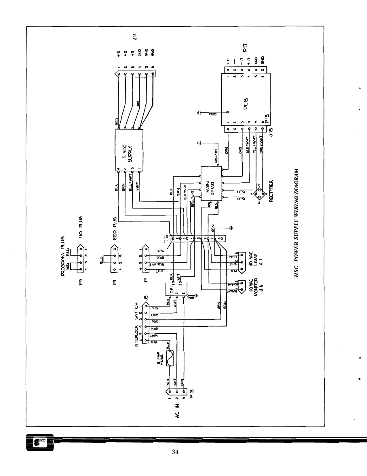
POWER SUPPLY
DESCRIPTION
PLUS 5 VOLT REGULATED POWER SUPPLY PART NUMBER
90-0094-00 ASSEMBLY, POWER SUPPLY 32-0002-00 130-0003-00 ASSEMBLY, TRANSFORMER 90-0017-00 77-0003-04 77-0003-04 65-0133-00 65-0134-00 58-0062-00 45-0012-00 40-0005-06 34-0002-00 31-0001-00 20-0007-00 GROMMET PRE-REGULATOR, PCB BLANK PRE-REGULATOR, PCB CHASSIS, POWER SUPPLY PROTECTIVE COVER, +5 VOLT POWER SUPPLY STANDOFF, PCB TERMINAL, TAB CONNECTOR, 6 PIN FUSE HOLDER FILTER, AC LINE RECTIFIER, BRIDGE
ISOLATION AND DC SUPPLY TRANSFORMER
Lisle) (e553)
OPTICAL SENSOR PCB | PART NUMBER DESCRIPTION
77-0020-04 77-0020-05 22-0070-00 21-0007-00 20-0012-00 13-1062-00 10- 1044-1 10-1201-02 10-6800-02 07-0004-00 02- 1032-00 02-1532-00 02-2222-00 02-5022-00 02-8242-00 PHOTO DETECTOR PCB BLANK PHOTO DETECTOR PCB LC., LM311 TRANSISTOR, 2N3904 DIODE, PHOTO (TELEFUNKEN 153P) CAPACITOR, 10uF CAPACITOR, .1uF CAPACITOR, 120PF CERAMIC DISC. CAPACITOR, 68PF CERAMIC DISC. CAPACITOR, VARIABLE 10K TE RESISTOR, 10K RESISTOR, 15K RESISTOR, 2.2K RESISTOR, 5K RESISTOR, 820K TURN TRI yror
77 0020 04
RIGHT ANGLE 3 POS. HEADER .100 CENTERS
Fig. 15 OPTICAL PCB
MISCELLANEOUS
PART NUMBER
00-0005-00 49-0069-05 35-0001-00 135-0024-00 137-0025-00 DESCRIPTION
CROSSBOW™ MANUAL AC POWER CORD AC LINE FUSE 5 AMP 110 AC PROGRAM PLUG 220 AC PROGRAM PLUG
This page carries no recoverable text. It is a drawing or a photograph. See the original scan.