Asteroids DP-143-5th-02A
Asteroids (rev 4) (Atari, 1979) · Drawing Package · 1 pages · original scan
nara ne
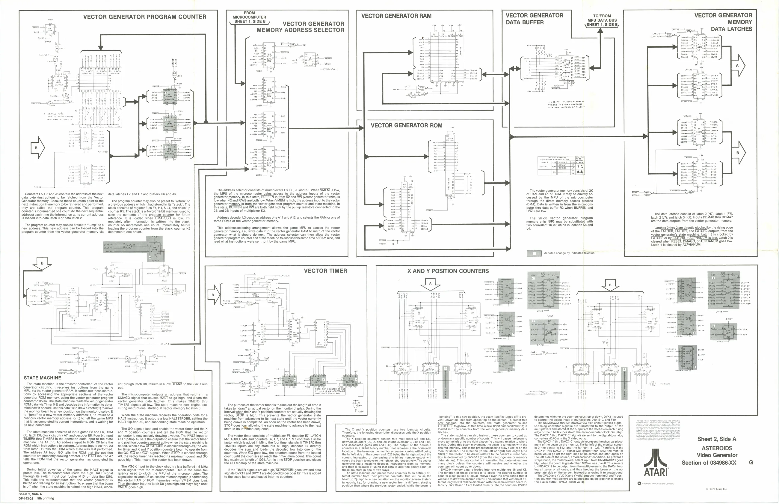
Counters F5, HS and JS contain the address of the next data latches F7 and H7 and buffers H6 and Jb. data byte (insiruction) to be fetched from the Vector Generator memory. Because these counters px
‘next instruction in memory to be retrieved and performed, ‘address) each time the information at its current address
they are called the program counter. Thi ‘counter is incremented one count (tothe next sequential
is loaded into data latch 0 oF data latch 2.
new address. This new address can be loaded into the ‘rogram counter from the vector generator memory via {to the The program counter may also be preset to “return” to a previous address whi
‘rogram stack consists of register files F4, H4, & J4, and downlup
counter 6, The stacks. ¢vord 12-bit memory, used to ‘save the conter reference. It is loaded when OMAPUSH is low. Im: ‘mediately after information is written into the stack, ‘The program counter may also be preset to “Jump” toa counter KS increments one count. Immediately before loacin the program counter om the stack, counter KS ements one count.
VECTOR GENERATOR PROGRAM COUNTER
‘had stored in its "stack" The
‘of the program counter for future
STATE MACHINE
‘The state machine is the “master controler” of the vector generator circuitry. It receives instructions trom the game
MPU, via the vector generator RAM It carries out these instruc: Counter to do so. The state machine reads the vector generator
tions’ by accessing the appropriate sections of the vector Generator ROM memory, using the vector generator program
OM data (via Timer 03) and decodes this information o deter:
‘mine how it should use this data: 1) to draw a vector, 2)'o move. the monitor beam to a new position on the monitor display; 3) to “jump” to a new vector memory address; 4) to return 10 a Previous vector memory address; or 5) to tell he game MPU
‘mine how it should use this data: 1) to draw a vector, 2)'o move that ithas completed its current instructions, and is waiting for 2, latch 08, clock circuitry A7, and decoder E8. Four bit input ROM which instructions to perform. Address inputs AO thru AS
Ns next command,
‘The state machine consists of input gates 88 and E6, ROM
TTIMERO thru TIMERS is the operation code input to the state machine. The Aé thru AB address input to ROM C8 tells the
from latch D8 tells the ROM which state was last performed, ‘The address A7 input GO tells the ROM that the position ‘counters are presently drawing a vector. The HALT input to A7 tells the ROM that the vector generaior has completed its ‘operations.
During initial power-up of the game, the FIALT signal is preset low. The microcomputer reads the high HALT signal through its switen input port (buffer M10) on data line DBO. This fells the microcomputer that the vector generator is halted and waiting for an instruction. To ensure that the beam is off when the state machine is halted, the high HALT, clock:
Sheet 2, Side A P-143.02 Sth printing 4 through latch 08, results in a low BLANK to the Z axis out ut.
“The microcomputer outputs an address that results in a [BHIAGO signal that causes HALT to go high, and clears the vector generator data latches. This makes TIMERO thru TIMERS signals all low. The state machine now begins execcuting instructions, starting at vector memory location 0. When the state machine receives the operation code for a TRALT instruction i outputs a low FALTSFROBE, setting the [HALT fiptlop A9, and suspending state machine operation.
‘The GO signals load and enable the vector timer and the X and Y position counters and tell the ROM that the vector {generator is now actively drawing a vector. The HALT input to GO tliptiop Ad sets the outputs to ensure thatthe vector timer {and position counters are not active when the state machine is halted. When a low GOSTROBE Is clocked through A®, the vec: tor timer and X and Y position counters begin to operate from the GO, GO and 80° signals. Wen STOP is clocked trough {AG, the vector timer has reached its maximum count, and {90e8 high. This means the vector has been drawn, ‘The VGCK input tothe clock circuitry is a butfored 1.5 MHz clock signal from the microcomputer. This is the same tre ‘quency used to clock the MPU of the microcomputer. The signal clocks latch D8 unless the microcomputer is addressing the vector RAM or ROM memories (when VMEM goes low Then the clock input to latch D8 goes high and stays nigh unt MEM goes high. VECTOR GENERATOR RAM VECTOR GENERATOR DATA BUFFER MICROCOMPUTER ‘SHEET 1, SIDE B MPU DATA BUS SHEET 1, SIDE B, VECTOR GENERATOR MEMORY ADDRESS SELECTOR VECTOR GENERATOR MEMORY DATA LATCHES
‘The address selector consists of multiplexers F9, H3, J8 and K3. When VMIEM is low, ing acoass to the address inputs of the vector rom 62 and WW (vector generator writ) Is iow. When VMEM Is high, the address input tothe vector, from the vector generator program counter and state machine. In ‘and VW are both held high by the pullup resistors connected to the 2B and 38 inputs of multiplexer K3. ‘The vector generator memory consists of 2K ‘of RAM and 4K of ROM. It may be directly ac ‘MPU of the ‘microcomput mory access process (OMA). Data is writen in from the microcomputer thru data buffer R2 when BUFFEN and the MPU of the microcomput
low when #2 ana through the direct
‘Address decoder 3 decodes address bits A11 and A12, and selects the RAM or one of The 2kx8 vector generator program three ROMS of the vector generator memory. memory chip NIP3 may be substituted with two equivalent 1Kx8 chips in location K4 and us This address-selecting arrangement allows the game MPU to access the vector ‘write data into the vector generator RAM to instruct the vector Generator what it'should do next. The address selector can then allow the vector ‘Generator program counter and state machine to access this same area of RAM also, and ead what instructions were sent to It by the game MPU. Latches 0 thru 2 are directly clocked by the rising edge ‘Outputs from the W's state machine. Latch 3 is clocked by Is tow. Latch 018, ‘generator memory,
cleared when FE: Latch 1 is cleared by ALPHANUM,
VECTOR TIMER
‘The purpose ofthe vector timer isto time out the length of tims takes to “draw” an actual vector on the monitor display. During Interval when the X and ¥ position counters are actually drawing the vector, STOP is high. This prevents th ‘machine from advancing to its next state until the vector currently being drawn is completed. As soon as the vector has been drawn, allowing the state machine to advance to the next vector generator state “jumping” to this now position, the beam itself is tuned off to provont unwanted lines from appearing on the screen. To preset this ‘slate gonerator causes ogo low. At this time, anew 122 number (OVXO-1) 8 fed into the counters from the vector generator memory data the counters count up or down, DVXI1 is used te contol the select Input of multiplexers D10, €16, and F0. ‘The UNMDACXG thru UNMOACKt0(& axis unmultploxed digital toanalog converter signals) are trarsterred to 1 lexersand stored at the outputs of the at ofthe. 6 MHZ clock (rom tl ‘The DACX'™ thru DAGKI0" signals avo sont tothe cigtalo-analog Convertors (OAC) inthe X video out "The DAGX'™ thru DACX10" output re ‘ment ofthe Beam on the monitor. The fa et of the monitor screen {8.0, the center Ie 512, an the far ght 18 1023, Therefore, the DAGXI® thru DAGX1O® signal was geater than 1023, the monitor eam would go off the right sige of the lot sido Othe sereon, a "wraparur ‘The X and Y position counters are two identical circuits serption alscusses only the X position ‘Theretore, the following ‘The vector timer consists of multiplexer F6, decoder E7, LATCH M7, ADDER M6, and counters 87, C7, and D7. M7 contains a scale facior which is added in MB to the four timer signals. I TIMERO thru TIMERS inputs are any state but all high, decoder E7 directly decodes the sum and loads the decoded’ low Into one of the Counters. When GO goes low, the counters count from the loaded ‘count until the counters all reach their maximum count. This count Is amaximum length of 1028. At this time STOP goes low and clears the GO fliptop ofthe state machine "Tho stato machine can also instruct these counter ‘ordown any specitic numberof counts. This "The X position cour downlup counters (69, D9 and E9), mul land associated gates (88 and Ht0). T Zit binary number that contaln rate mult tance relative to whe! {Rwao, During thie beam movement, the beam le turned on with the Sty. This sth procedure used to draw a vector onthe or righ) and fength © to ‘Beam'e current post. ors (010, £10, and F10), ‘output of the down presents the norizont sent the physical place:
‘monitor soreon. The direction to the 5023) ofthe vector tobe drawn relative to tion Is determined by DVX0-1 (rom {ata latches). This data contains information that ‘many clock pulses tt Counters will count up ar down. ‘DVX0' memory data is loaded into rate multipliers JB and K8, ‘The function ofthese dovices Is to space the desired number of counter clock pulses at equal intervals over th sired vector. This ineures that vectors o {erent engine wil stil be splayed with the same relative beam In. tensity: OVX10 and 11 are loadeg rectly into the counters, DVXI0 location of the Beam on the moniter sereon (or X axis), with 0 being and siart again on nation. To prevent a ft nput from UNMDACK11 goes ‘than 0. This selects igh won the count sg LUNMDACXT2 tobe output trom the rultiploxers tothe DACs, fore: Ing all zeros o all ones, and thus feaping the beam on the appropriate sido onthe sereen, Insteadot allowing i to wraparound, ‘The XVLD and YVLD Ocand Y valid) gutpute from the Xana Y posi tlon counter multiplexers ar latchedand gated together to enable the Z axle output, BVLD (oeam valid}. Ifthe TIMER signals are all high, ALPHANUM goes low and data signals DVX11 and DVY11 are decoded by decoder E7. This is added tothe scale factor and loaded Into the counters. these counters in one of two ways. “Te state machine can preset these counters to an entirely dit foront number from thelr previous. contents. This will causa the ‘beam to "jump" to.a new location on the monitor screen insta for arawing a now vector Irom a itfrent starting position than were the previous vector ended. Whi wl take to draw the The data latches consist of latch 0 (H7), latch 1 (F7), latch 2 (J7), and latch 3 (K7). Inputs DDMAO thru DDMA7- ‘are the data outputs from the vector generator memory.
‘9088 low.
Sheet 2, Side A
ASTEROIDS
G
© 1979 Ata, ne