Choplifter
Choplifter (8751 315-5151) (Sega, 1985) · Document · 11 pages · 13 sections · original scan
2ND PRINTING— NV
INSTRUCTION MANUAL
FOR HORIZONTALLY
MOUNTED MONITOR
SEGA enterpRIsES, INC.
2149 PARAGON DR. SAN JOSE, CA 95131 (408) 435-0201 PPI LMP Sooo % KK ISK KPIS % Kodo SBS Sedo K HSS Ks HIS K Po HIB 1 powwwewwwwrerwvereweweswrwwverererreserersusts : PLP LLLL ELL FEL PEELE EL EERE LEE EE MANUAL NO. 420-5270-91
CCNTENTS
RECOMMENDED WIRING DIAGRAM
WIRING ROUTING (MAIN HARNESS)
WIRING ROUTING (CONTROL PANEL HARNESS)
OPTION SWITCHES / DC POWER REQUIREMENTS
KIT CONTENTS
CONVERSION KIT CONTENTS
PC Board
Generic Main Wiring Harness Control Panel Wiring Harness 8 Way Joystick Assembly Screws and Nuts for Joystick (4) Push Button Assemblies (6) Control Panel Overlay Monitor Card Side Decals (2)
Plastic Marquee Instruction Manual
License Seal
PREVENTION OF COUNTERFEITING AND CONVERSION
LABELING
To prevent counterfeits and conversions, the following labels are put on all the SEGA products. When handling such goods, be sure to confirm the labels. They are used to prevent illegal acts such as the unauthorized copying of the products and the printed circuit boards thereof or carrying on business by manufacturing similar merchandise or by converting, selling or using such products or printed circuit boards.
ORIGINAL SEAL LICENSE SEAL
The following seal is put on The following seal is put on the machines manufactured by the kits, such as the printed SEGA. circuit boards, of SEGA
products.
ea ae a ie
COPYRIGHT NOTICE This SEGA product has the copyright notice as follows:
© SEGA 1985
This signifies that this work was disclosed in 1985 and is
the property of SEGA ENTERPRISES, LTD.
NOTICE WARNING
After installation of this kit, the 5 volt power supply
must be checked and adjusted to make certain exactly 5 volts are present at pins 1 & 3 (1 is negative and
3 is positive ) of the 44 pin edge connector. The voltage check and adjustment must be done while the PCB is
plugged in to the 44 pin connector to supply the proper
load. This PCB will not operate properly on voltages
below 5 volts as measured at the board.
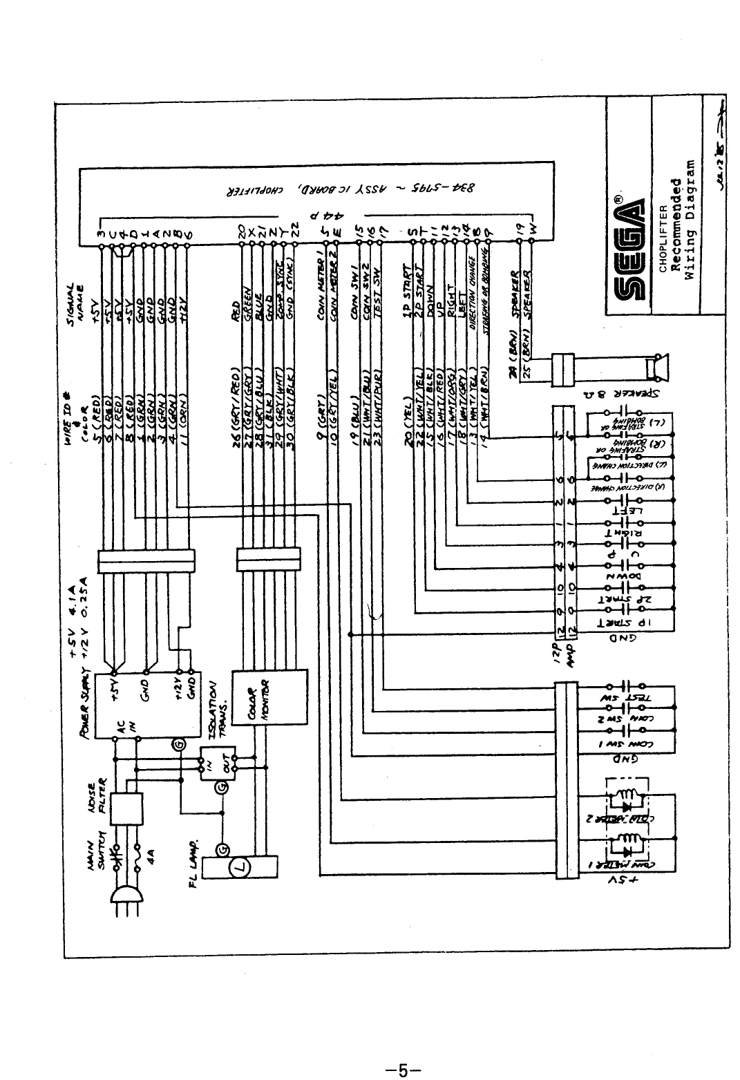
This page is a drawing, shown as the original scan.
DISTINATION
POWER SUPPLY GND/RETURN
POWER SUPPLY
+5V
COIN METER 1
COIN METER 2
JOYSTIC RIGHT SWITCH
JOYSTIC LEFT SWITCH
JOYSTIC UP SWITCH
JOYSTIC DOWN SWITCH “STRAFING OR BOMBING” PUSH BUTTON “DIRECTION CHANGE” PUSH BUTTON
1P START BUTTON
2P START BUTTON
COIN MECH 1
COIN MECH 2
TEST MODE SWITCH
SPEAKER
RED
GREEN
COLOR BLUE MONITOR ) COMP, SYNC GND (SYNC)
GND 44PIN
WIRE ID # SIGNAL NAME
1 GND
GND 7
| 2 | GND | a |
| 3 | GND | 2 |
| 4 | GND | B |
| 5 | +e | 3 |
| 6 | +5V | c |
+5V T 7 4 +
| 8 | EV | | | D |
| ° | COIN METER 1 | 5 | |
| 7 | COIN METER 2 | e | |
| " | +12 | 6 |
Fr JOT
| 2 | N | USED | 7 |
H
| WHT/ORG | 1P_ DIRECTION CHANGE | 8 |
WHT/GRY J
| # | WHT/RED | Le STRAFING OR BOMBING | g |
| 5 | WHT/BLK | k |
| a | WHT/BRN | 10 |
| aa | WHT/YEL | L |
e
| = | 1P_DOWN | " |
< & M
| Pay | YEL = | 1P UP | 42 |
| z | WHT/YEL. | N |
8 1P_RIGHT GRN P
1p LEFT “
R
| B | cOIN swt | 15 |
4P_ START s
| “4 | COIN sw 2 | . |
2P START T
| 16 | TEST SW | 7 |
u
v
| i 16 | SPEAKER | 19 |
| ” | SPEAKER | w |
| 18. | RED | 2 |
| 19 | GREEN | x |
| 2 | BLUE | an |
COMI YN
| a | = =< ic | Y |
| 2 | GND (SYNC) | 2 |
GND z 23;
[_CHOPLIFTER WIRE ROUTING EDGE CONNECTOR
WIRE COLO
GRN
GRN
GRN
GRN
RED
RED
RED
RED
GRY
GRY/YEL,
one
WHT/GRN
WHT/YEL
WHT/BRN
WHT/BLK
WHT/RED
WHT/ORG
WHT/GRY
BLU
YEL
WHT/BLU
WHT/YEL,
WHT/PUR
BRN
BRN
GRY/RED
GRY/GRN
GRY/BLU
GRY/WHT
GRY/BLK
BLK
IP YELLOW
REE jie START
ae START
WHITE la Z BROWN STRAFING OR GOMBING CLEFT) GREEN
CONTROL PANEL ARNESS
COIN / CREDIT OPTION
SWITCH SETTING
CHOPLIFTER ( 834 — 5795 )
DIP SWITCH FA
OPTION s [es
COIN 1 CREDIT 1 COIN 2 CREDITS 1 COIN 3 CREDITS 1 COIN 4 CREDITS 1 COIN 5 CREOITS
1COIN 6 CREDITS
2COINS 1 CREDIT
- COINS 1 CREDIT 4COINS 1 CREDIT
2COINS 3 CREDITS
1[2]sa]« orF| ofr] oFF| oFF on | oFF| oFF] OFF oFF| on | oFF| oFF on | on | oFF orr| oFF| on | OFF on | oFF| on | oFF OFF| ON | ON | OFF on | on | on | oFF OFF| ON on | ofF| oFF| ON orr| OFF on | OFF orF| ON on | on ore | OFF on | OFF corr | on orF| OFF ON | OFF OFF OFF OFF OFF on ON ON ON OFF OFF OFF OFF OFF OFF OFF OFF OFF OFF ON on
2.COINS 1 CREOIT
2 CREDITS
3 CREDITS
4 CREOITS orF| on | oFF] on OFF on
2 COINS 1 CREDIT
- COINS 3 CREDITS on | on | oFF| on OFF on
COIN 1 CREOIT
2COINS 2 CREDITS,
3 COINS 3 CREDITS 4.COINS 4 CREDITS S.COINS 6 CREDITS oFF| oFF| on | on ore | oFF ON oN
COIN 1 CREDITS 2COINS 2 CREDITS 3 COINS 3 CREDITS 4 COINS § CREDITS on | off | on | on on | oFF on on
1 COIN 2 COINS 1 CREDIT
orF| on | on | on corr | ON on oN
COIN 1 CREDIT on | on | on | on on | on oN ‘ON
OPTION SWITCH SETTI “To com swirew COIN Swi TCH #2
NG oO switel He.
[orto 1 [2 [3 [¢@
TABLE UPRIGHT OFF ON [hover tise oFF SOUND on OFF
PLAYER, 2 HELICOPTER, 4 FAee| orr | oe on [OFF ‘OFF TON ‘ON [ON
20000, 70000]
SCORE OF +¥20000, 170000] ADDITIONAL "Zope" PLAYER +s0000,200000| OFF on
GAME DIFFICULTY EASY HARO OFF ‘ON NoT use
Le DIP ol SWA iP SWB BARE BD No. 171-5303 BARE BD N DIP SWB DIP SWA ews jo. 171-5054-03 44PIN P=3.96mm
COMPONENT SIDE GND — SOLDER SIDE GND
BLUE a > CMP SYNC
RED a SPEAKER —2 SERVICE SW. —42 ‘TEST SW. = GREEN SPEAKER | NOT USED NOT USED
COIN SW. 2 a COIN SW. 1 2 2P START IP START
1p LEFT. =I 1p RIGHT —a 2p LEFT 1P RIGHT
1p UP a 1P DOWN = 2P UP 2P DOWN
NOT USED NOT USED
iP STRAFING OR BOMBING o 1P DIRECTION CHANGE §=———] >!
NOT USED 2P STRAFING OR BOMBING 2P DIRECTION CHANGE NOT USED
+2V 2 COIN METER 1 1 NOT USED COIN METER 2
+5V { = Jesv
GND ‘yoann JOYSTICK CONTROL DIRECTIONS
wl o O STRAFING OR BOMBING O DIRECTION CHANGE, SUPPLY VOLTAGES & CURRENT
VOLTAGE CURRENT
Dcsv Dev 0,25.A
This page reads as a drawing: its text was drawn rather than typeset, and comes out in fragments. See the original scan.
This page reads as a drawing: its text was drawn rather than typeset, and comes out in fragments. See the original scan.