Route 16
Route 16 (Sun Electronics, set 1) (Sun Electronics, 1981) · Manual · 27 pages · 25 sections · original scan
O0TO-Z9-99€ “ON 32ed \ IWANVAN ADIAESS LSS FI aM v's'n' vaiuols ‘ HV31VIH ™“LNWII WL
ROUTE 16
CENTURI, INC,
245 W, 74TH PLACE
HtALeaH, FL. 33014 Tec. #(305) 558-5200
CUSTOMER SERVICE:
Ter. #(305) 558-5200 (In Frorrpa)
Tet, #(800) 327-7710 (Outsipe FLoripDA)
Il.
III.
Iv. ROUTE 16 TABLE_OF CONTENTS
PAGE NO. INTRODUCTION: USER INFORMATION - F.C.C.
GAME DESCRIPTION (DIAGRAM)
GAME SUMMARY
SPECIFICATIONS:
INSTALLATION ......-.--- see
ELECTRICAL REQUIREMENTS
110/220 CONVERSION INSTRUCTIONS
OPERATION:
GAME INSTRUCTIONS
GAME SCORING 1... eee eee e cect enter erent ete e teen e teen nee eeee 6 OPERATOR OPTIONAL SWITCH SETTINGS .......... ceed tenet e eens 7 OPTIONAL SWITCH SETTINGS 12... 0... cece eee cence eee e tence eeee 7
ROUTINE MAINTENANCE & SERVICE 10... se ee cece ecee cece enter cence 8 POWER SUPPLY .......... sie ese oe eet ewes we eee ss seenes Sint oa we anes 8
GENERAL: ROM A6 PRINTED CIRCUIT BOARD PARTS LIST
C.P.U. PRINTED CIRCUIT BOARD PARTS LIST
POWER SUPPLY PARTS LIST ...... cece cece cece cece erence renee
CONTROL DECK ASSEMBLY - EXPLODED VIEW .
COIN DOOR ASSEMBLY - FIGURE 1 .......--eee
COIN DOOR ASSEMBLY - FIGURE 2 ..........+---
DRAWINGS: 110/220 POWER INTERCONNECT DIAGRAM ............. (361-10-0900)..17 C.P.U. HARNESS DIAGRAM .......+eeee eee beer ee eee (366-12-0100) ..18 POWER SUPPLY SCHEMATIC ..... eee esses ence e ee eeee (363-17-0300)..19 COIN DOOR WIRING DIAGRAM ...... eee ee eee eee eee ee (364-62-1000) ..20
CPU/LOGIC BOARD SCHEMATICS: SOUND BOARD (1 Of 8)... cece eee cece eee eee eens (366-10-0400)..21 Sl BOARD (2 Of 8B) Je. cece e eee eee ee eee eee eee (366-10-0400) ..22 VRAM2 BOARD (3 of 8)
CPU-2 BOARD (4 of 8)
- (366-10-0400)..23
- (366-10-0400) ..24
VRAM-1 BOARD (5 Of 8)....- eee eee eee eee eee eee (366-10-0400) ..25 CPU-1L BOARD (6 Of 8) wc. cece eee eee eee neces (366-10-0400) ..26 DUAL PORT RAM (7 Of 8) oe cece cece cece ree eee (366-10-0400) ..27 IN/OUT BOARD (8 of 8) ..... he EER eRe eae eee (366-10-0400)..28
USER_INFORMATION - F.C.C.
This equipment generates, uses and can radiate radio frequency energy and if not installed and used in accordance with the instructions manual, may cause interference to radio communications. As temporarily permitted by regulation, it has not been tested for compliance pursuant to Subpart J of Part 15 of F.C.C. Rules, which are designed to provide reasonable protection against such interference. Operation of this equipment in a residential area is likely to cause interference in which case the user at his own expense will be required to take whatever measures may be required to correct the interference,
VIEWING GLASS
CONTROL PANEL
RIGHT SPEED TTO LEFT SPEED BUTTON
COIN DOOR JOYSTICK ASSEMBLY (4-DIRECTION
LINE CORD
19" "ROUTE 16" VIDEO UPRIGHT
ROUTE 16
GAME SUMMARY
Route 16 is a challenging race car game, integrating special features to excite the beginner as well as the seasoned player. The vivid video screen is fascinating, and is complimented by exceptional audio during game play.
The red car is controlled by the joystick feature, and is pursued through 16 different routes (mazes) by three chase cars. The search mode reveals an overview of all 16 routes, and the search mode appears whenever the car exits a route. In the search mode, the player car becomes a red cube, and the chase cars become yellow cubes.
Whenever the player car exits one route, there is a one second delay for a total overview of the game.
Each route has dead-ends, zig-zags, and multiple entrances and exits.
Some routes have the dollar symbol ($), and the player scores 200 points each time this symbol is cleared. The dollar symbols randomly change to oil slicks, and when encountered, the oil slicks slow down the player car.
The guestion mark symbol (?), is surrounded by check points (Q), and will either reveal a bomb symbol or a bell mark after the player car clears the check point. The bell will add 800 points to the player's score when cléared. Player skill is tested here to avoid the bomb if it appears.
Some routes have a flag symbol, and when the player car clears the symbol, the pursuing cars become dollar symbols, and every effort should be made by the player to chase them down, and add extra points to his score.
One route has a flickering bonus car symbol. When the symbol appears, clear it and earn an additional player car.
One route has an additional game feature. When the player car enters the maze, it is pursued by an attacking monster. The player car cannot clear or collide with the monster, but must avoid it, or be destroyed.
‘The high-speed button is another feature of Route 16. When pushed, the player car is accelerated to escape the chase cars. Usage of the high-speed button reduces the player car's fuel. At the end of each round, bonus points are added to the player's score for remaining fuel.
After all the symbols are cleared, the round ends. In successive rounds, additional dollar symbols ($), and additional enemy chase cars are added.
The game is over when all the player cars have crashed.
INSTALLATION
Your game was shipped from the factory in ready-toplay condition. A brief inspection is suggested before the machine is removed from the carton. If there is damage to the shipping carton, contact the freight carrier for claim purposes. External damage could indicate possible damage to the cabinet and/or electronic components.
After the carton has been satisfactorily inspected, remove the machine from the shipping carton.
Examine the interior of the game for disconnected wires, cables or harnesses and make sure electronic devices are securely mounted in their sockets, etc. Record the game serial number, since it will be required for reference and servicing.
ELECTRICAL REQUIREMENTS
Unless otherwise specified, this game is set to operate at 110 Volts A.C. See Figure (1) for 110/220 VAC conversion instructions.
Power Supply Chassis schematic information and parts list are included in this manual.
110/220 VAC CONVERSION INSTRUCTIONS
This video arcade game has a harnessing configuration that allows the machine to be operated from either a 110 VAC or 220 VAC @ 50 or 60 Hz power source, with only minor changes. The only items requiring a change are the fuses and the jumper plug on the game power transformer.
First, unplug the machine from the wall outlet to completely eliminate shock hazards.
Next, remove the two fuses in the A.C. distribution bracket.
Then, remove the jumper plug on the game power transformer located on the floor of the machine.
Now, depending on what voltage you wish to run the game from, do the following:
110 VAC: Replace the two fuses that go in the bracket with 3-AMP SLOW-BLOW types. Next, plug in the ORANGE jumper plug labeled 110 VAC. The machine can now be operated with an input voltage of 110 Volts AC.
220 VAC: Replace the two fuses that go in the bracket with 1 AMP SLOW-BLOW types. Next, plug in the RED jumper plug labeled 220 VAC. The machine can now be operated with an input voltage of 220 volts Ac.
All games shipped from CENTURI, INC. are in the 110 VAC configuration.
ROUTE 16 - GAME INSTRUCTIONS
as INSERT COIN.
- SELECT ONE-PLAYER OR TWO-PLAYER BUTTON.
- JOYSTICK CONTROL MANUEVERS PLAYER CAR IN FOUR DIRECTIONS, ENABLING CAR TO TRAVEL THROUGH EACH "ROUTE" (MAZE), AND ENTER AND EXIT EACH "ROUTE".
- HIGH SPEED BUTTON ACCELERATES PLAYER CAR, BUT DECREASES FUEL.
- POINTS ARE SCORED BY CLEARING SYMBOLS ON EACH ROUTE.
- BONUS POINTS ARE SCORED WHEN ALL SYMBOLS ARE CLEARED BEFORE FUEL IS DEPLETED. BONUS POINTS ARE ADDED AS TEN (10) TIMES FUEL BALANCE.
- BONUS CAR IS ADDED WHEN PLAYER CAR CLEARS FLASHING CAR SYMBOL.
- CLEARING FLAG MARK CHANGES ENEMY CARS TO DOLLARS ($) POINTS.
- MYSTERY MARK (? MARK) IS REVEALED AS A DOLLAR SYMBOL OR BOMB SYMBOL WHEN PLAYER CAR CROSSES CHECK POINTS SURROUNDING MYSTERY MARK.
- GAME IS OVER WHEN ALL PLAYER CARS HAVE CRASHED.
GAME_SCORING
POINT VALUES
“aa : #l@l4 eG g pT 2 point “points | “B0Upoints To fotmtolen ALL ROUTES VIEW:
OPERATOR OPTIONAL SWITCH SETTINGS
The option switches are located on the CPU Board. The option switches and audio control can be reached through the back of the machine.
The following table will assist your adjustments:
OPTIONAL SWITCH SETTINGS
Switch 1 controls the number of cars alloted each player per game. The switch settings should be as follows:
SWITCH 1: NUMBER OF CARS: OFF 3 On 5
Switches 2 and 3 are not used.
Switches 4 and 5 control the game fees. These settings can be set for one coin (25¢) or two coins (50¢) per play as follows:
| SWITCH 4: | SWITCH 5: | COIN SETTING: |
| OFF | OFF | One Coin (25¢) - One Play |
| ON | OFF | Two Coins(50¢) - One Play |
Switch 6 is a preset factory adjustment, and should remain in the "ON" position for the video upright game.
Switch 7 is preset at the factory, and should be set in the "ON" position for the monitor picture adjustment.
Switch 8 allows the operator to regulate the availability of music in the attract mode. The following settings regulate this function:
SWITCH 8: ATTRACT MODE MUSIC: ON Music Available OFF Music Not Available
ROUTINE MAINTENANCE & SERVICE
Because of the solid state electronic circuitry, this machine should require very little maintenance and only occasional adjustments. However, it is necessary to take measures to insure this.
The volume control is located on the bottom side of the printed circuit board farthest from the side of the cabinet, and can be accessed through the rear door.
The video monitor has been properly adjusted before shipping. Occasionally minor adjustments are necessary, see monitor specifications and schematics for technical information. Adjustment controls for the monitor are located at the rear of the monitor.
This machine should be serviced only by a qualified technician.
Do not make any adjustments on this machine while the power is on.
For service information, contact:
CENTURI, INC.
Customer Service Department
#800-327-7710 (Outside the state of Florida)
#305-556-5888 (In Florida)
POWER SUPPLY
The Computer Board in this game operates most efficiently and reliably when the power supply is set so that the voltage on the board is 5.0 Volts, +0.1 Volts. To check this, place ameter across 5 Volts and ground at the edge connector. If necessary, adjust the screwdriver control on the power supply so that the meter reads between 4.9 and 5.1 Volts.
ROM _A6 PRINTED CIRCUIT BOARD #50330010
PARTS LIST
NO. PART NUMBER: DESCRIPTION: USAGE:
| 1 | 50010306 | MB8841 | 1 |
| 2 | 50010264LS | 74LS368 | 3 |
| 3 | 50010105LS | 74LS32 | 1 |
| 4 | 50010139LS | 74LS175 | 1 |
| 5 | 50040002 | -l mfd, 50 Volt Ceramic Disc Cap. 3 | |
| 6 | 50040141 | .00lmfd, 50 V., Ceramic Disc Cap. 1 | |
| 7 | 50040170 | 220PF, 50 V., Ceramic Disc Cap. | 1 |
| 8 | 50060178 | 4.7mfd, 10 V. Tantalum Capacitor 1 | |
| 9 | 50100014 | 1N914 Diode | 1 |
| 10 | 50030063 | 10K, 1/4 W., 5% Resistor | 1 |
| 11 | 50030147 | 6.8K Ohm, 1/4 W., 5% Resistor | 1 |
| 12 | 50030006 | 4.7K Ohm, 1/4 W., 5% Resistor | 1 |
| 13 | 50210222 | Printed Circuit Board | 1 |
| 14 | 50150297 | Sguare Pin Straight Wafer, |
(Molex #22-03-2121) N
C.P.U. PRINTED CIRCUIT BOARD #50330011
PARTS LIST
NO. PART NUMBER: DESCRIPTION: USAGE:
| 1 | 50010233 | TMS 4116 I.c. | 16 |
| 2 | 50010028LS | 74LS153 I.C. | 8 |
| 3 | 50010019LS | 74LS74 I.C. | 5 |
| 4 | 50010045LS | 74LS157 I.C. | 9 |
| 5 | 50010096LS | 74LS08 I.Cc. | 2 |
| 6 | 50010002LS | 74LS00 I.c. | 7 |
| 7 | 50010025LS | 74LS95 I.Cc. | 4 |
| 8 | 50010007LS | 74LS10 I.c. | 4 |
| 9 | 50010005LS | 74LS04 I.c. | 7 |
| 10 | 50010008LS | 74LS20 I.C. | 1 |
| 11 | 50010022LS | 7ALS86 I.C. | 4 |
| 12 | 50010264LS | 74LS368 I.C. | 10 |
| 13 | 50010012LS | 74LS30 I.c. | L |
| 14 | 50010204LS | 74LS393 I.c. | 2 |
| 15 | 50010139LS | 74LS175 I.C. | 1 |
| 16 | 50010014LS | 74LS42 I.C. | 3 |
| 17 | 50010105LS | 74LS32 I.c. | 6 |
| 18 | 50010242 | 2114 (MPD 2114 - Lc-3) | 2 |
| 19 | 50010195LS | 74LS367 | 10 |
| 20 | 50010305 | MB7052 | 2 |
| 21 | 50010030LS | 74LS174 | 3 |
| 22 | 50010004LS | 74LS02 | - tL |
| 23 | 50010171 | 2716 | 10 |
| 24 | 50010187 | 2-80 C.P.U. | 2 |
| 25 | 50010307 | 7946 (Sound Chip AY-3-8910) | I. |
| 26 | 50130034 | 8-Position DIP Switch | 1 |
| 27 | 50040002 | .lmfd, 50 Volt, Ceramic Disc Cap.20 | |
| 28 | 50040066 | 470PF, 50 V., Ceramic Disc Cap | 3 |
| 29 | 50040005 | 0.0lmfd, 50 V., Ceramic Disc Cap. 1 | |
| 30 | 50040168 | 30PF, 50 V., Ceramic Disc Cap. | 1 |
| 31 | 50040141 | 0.00lmfd, 50 V. Ceramic Disc Cap. 1 | |
| 32 | 50030095 | 330 Ohm, 1/4 W., 5% Resistor | 2 |
| 33 | 50030063 | 10K Ohm, 1/4 W., 5% Resistor | 3 |
| 34 | 50030150 | 47K Ohm, 1/4 W., 5% Resistor | L |
| 35 | 50040125 | 220 Ohm 1/4 W., 5% Resistor | 2 |
| 36 | 50030310 | 560 Ohm, 1/4 W., 5% Resistor | 1 |
| 37 | 50030091 | 56K Ohm, 1/4W., 5% Resistor | 1 |
| 38 | 50030185 | 1.8K Ohm, 1/4 W., 5% Resistor | 1 |
| 39 | 50030051 | 1K Ohm, 1/4 W., 5% Resistor | 2 |
| 40 | 50030007 | 100K Ohm, 1/4 W., 5% Resistor | 1 |
| 41 | 50360010 | 2.2K Ohm, 1/4 W., 9-Pin SIP |
Resistor 3
| 42 | 50070016 | 10MH, Crystal | Ag |
| 43 | 50020065 | TIP 120 NPN Darlington Transistor 1 | |
| 44 | 50060176 | 0.47mfd, 16 V., Tantalum Cap. | 1 |
| 45 | 50060177 | 100mfd, 16V., Radial Lytic Cap. 3 | |
| 46 | 50060156 | lOmfd, 16V., Radial Lytic Cap. | 1 |
| 47 | 50060139 | 47mfd, 16V., Radial Lytic Cap. | 1 |
C.P.U. PRINTED CIRCUIT BOARD #50330011
PARTS LIST Page -2-
NO. PART NUMBER: DESCRIPTION: USAGE:
| 48 | 50040169 | -lmfd, 50 V. Mylar Capacitor | 1 |
| 49 | 50150111 | 16-Pin I.C. Socket | 4 |
| 50 | 50150061 | 24-Pin I.C. Socket | 11 |
| 51 | 50150112 | 18-Pin I.C. Socket | 2 |
| 52 | 50150060 | 40-Pin I.C. Socket | 2 |
| 53 | 50010271 | MB3713 Audio Amplifier | 1 |
| 54 | 50100014 | 1N914 | 1 |
| 55 | 50080034 | 100K Potentiometer, CTS 375 V. | 1 |
| 56 | 50210223 | P.C.B. Route 16, C.P.U.-Logic | 1 |
| 57 | 50175506 | Jumper, 22GA, insulated Wire | 36" |
-1l-
POWER SUPPLY #50350001
PARTS LIST
| SYMBOL: | DESCRIPTION: | USAGE: |
| Tl | Transformer, Single Phase, 24 VA | 1 |
| Ll | Coil, 1.6 mH, 1.5A | 1 |
| L2, L4 | Coil, SF-T8-50S-03 | 2 |
| L3 | Coil, SF-HP-2A-03 | 1 |
| DL | Diode, V19G | 1 |
| D2 | Diode, VO6C | 1 |
| D3, D6 | Diode, 151588 | 2 |
| D4 | Diode, S15S3 | 1 |
| D5, D7 | Diode, 5CH1M | 2 |
bD12, D13 Diode, F113B 2
| p14 | Diode, F113B | 1 |
| RFL | Diode, S4VB40 (Bridge Type) | 1 |
| Ql | Transistor, 28C2504 | 1 |
| Q2 | Transistor, 2SD467 (B) | 1 |
| Q3 | Transistor, 2SC460 (B) | 1 |
| 24 | Transistor, 2SA673 (B) | 1 |
tcl Integrated Circuit, RM723DC or HA17723G-02 1
| Pcl | Photo Coupler, PS2001 | 1 |
| RL | Resistor, 2 Watt, 18 Ohm | 1 |
| R8, R9 | Resistor, 2 Watt, 47K Ohm | 2 |
| R3, 1-4 | Resistor, 2 Watt, 15 Ohm | 4 |
| R4 | Resistor, 1 Watt, 56 Ohm | 1 |
| R12 | Resistor, 1 Watt, 100 Ohm | 1 |
| R28 | Resistor, 1 Watt, 470 Ohm | 1 |
| R7 | Resistor, 1 Watt, 0.56 Ohm | 1 |
| R26 | Resistor, 1 Watt, 0.82 Ohm | 1 |
| R23 | Resistor, 1/4 Watt, 22 Ohm | 1 |
| RLO | Resistor, 1/4 Watt, 33 Ohm | 1 |
| R27 | Resistor, 1/4 Watt, 68 Ohm | 1 |
| R2 | Resistor, 1/4 Watt, 330 - 470 Ohm | 1 |
| R22 | Resistor, 1/4 Watt, 220 Ohm | 1 |
| R21 | Resistor, 1/4 Watt, 270 Ohm | 1 |
| R6 | Resistor, 1/4 Watt, 330 Ohm | 1 |
| R11 | Resistor, 1/4 Watt, 68 Ohm | 1 |
| R20 | Resistor, 1/4 Watt, 470 Ohm | 1 |
| R17 | Resistor, 1/4 Watt, 680 Ohm | 1 |
| R19 | Resistor, 1/4 Watt, 800 Ohm | 1 |
| R18 | Resistor, 1/4 Watt, 1.2K Ohm | 1 |
| RS | Resistor, 1/4 Watt, 10K Ohm | 1 |
| R16 | Resistor, 1/4 Watt, 220K Ohm | 1 |
| R29 | Resistor, 3 Watt, 27 Ohm | 1 |
| R39 | Resistor, 1/4 Watt, 4.7K Ohm | 1 |
| R38 | Resistor, 1/4 Watt, 5.6K Ohm | 1 |
| R24 | Resistor, 1/4 Watt, 330 Ohm | 1 |
| R25 | Resistor, 1/4 Watt, 150 Ohm | 1 |
| RVL | Variable Resistor, RJ-6P501 | 1 |
SYMBOL: POWER_SUPPLY
TS LIST
DESCRIPTION:
cl, C2 C3-1,-2 c9, C10 cll, C23 Capacitor, ECK-DAL102E Capacitor, 160VSN100 Capacitor, SM10VB-2200 Capacitor, SM1LOVB-2200 c12,C13,C15Capacitor, SL25VB-10 C27 Capacitor, SL25VB-10 C18,C19,C20Capacitor, SM35VB-1000 C26 Capacitor, SM35VB-1000 C21,C22,C25Capacitor, SM16VB-1000 cs cé c14,cl6 c4 c8 c5-2
1, F2 Capacitor, DMY21H472K Capacitor, DMY21H104K Capacitor, DMY21H222K Capacitor, CM20XC511K5 Capacitor, MDD22G473K Capacitor, DMY21H222K
Enclosed Type Fuse, 3A #50350001
Page -2-
USAGE:
PREEPNFPRWRPWHWNNYNN
N
vees.i av 366-03-0S500 [JOYSTICK MOUNTING BRKT 36/-03- 0600] DECK € GiASS ANGLE BRET _ S01 300$B | JOYSTICK (4 POStTiou) TAITE lONLCOG | #10-24,34 CARR Ba}. BLD 10150207 KERS NuT#/0-24 _ 10111004 _|#10-24y' CARR.BolT BLO, S0/20050 | PALNUT - 50/30049 | KED BUTTON Assy 50/3 0088 | WHITE BUTI ASS $0120047_ |SWITCHFBEKT | 366-0/-0500| Caw7@od PAVE $ONRRAY HSS Y | PRT NO DESCRIPTION BILL OF MATERIAL [rhe | ac. APy’D | PROD. APV’D
ASSEMBLY NO
TOLERANCES
centu ine. HIALEAH, FLORIDA 33014
Uniess Otherwise Specified FRACTIONS
DECIMALS 2 PL
CONTROL DECK ASS\Y MATLS. "Rear TREAT. FINISH
REV. LET. + DECIMALS3PL + .005 + + HOLES 7 RT NO. REV.
ECN even | By | ANGLES DWN. APP'D, [DATE SCALE [PART NO.
. SHT. MET BENDS + AAM 4-6-8! | Be | 366-0/-0800
Index No.
Btgeovonsen Part No.
404429
400-8 904782 904706
904822 404352 400-4 904722 904762 100-6-3 404354
904936 100-4-12 404353
900651 2800 SERIES COIN DOOR EXPLODED VIEW
25¢ U.S. COIN
FIGURE 1
Description Inner Panel With Levers Sub-Assembly Nut Toggle Switch Test Switch Decal Custom Harness Assembly Insulation Coin Counter Assembly (6 Volt D.C.) Nut Wire Key Holder Switch Cover Screw C.R.E.M. Coil Assembly. 12 Volts D.C. Keeper Screw Coin Switch Assembly for U.S. 25¢ Coin Retainer Index No. Part No.
904710-1
904845 904701 904598 404428
5301-10 905115 110-4-6 904717
904716 404418 904594 904712 116-4-8 904704 Description
Silver Switch Wire — for U.S. 25¢ Coin Switch Coin Chute Coin Return Box Switch and C.R.E.M. Coil Bracket Assembly 25¢ Acceptor Bar Screw Miniature Bayonet-Base Lamp Socket #47 Lamp (6.3 Volt) Coin Inlet Chute Sub-Assembly Right Half of Coin Intet Chute “U"-Type Fastener Screw Slam Switch Assembly
Index No.
Oo nao Part No.
404341 404341-1 404348-1
904591 904703 904589-2
904707-1 2800 SERIES COIN DOOR EXPLODED VIEW
25¢ U.S. COIN
FIGURE 2
Description
Coin Door Only (2 Coin) Coin Door Only (3 Coin) Coin Return Button Assembly for U.S. 25¢ Coin Coin Return Button U.S. 25¢ Price Decal Coin Return Button Cover for U.S. 25¢ Coin Lock Assembly Index No. Part No.
345-4-5 904588 325-4-4 904590 904599 904581
406-416 904734 404357 Description
Screw Coin Button Housing Screw Coin Return Beze! Coin Return Cover Coin Door Frame, 11-5/8" x 13-3/8” Mounts in a 10-3/8" x 12-3/16" Opening Hex Nut Carriage Bolt Locking Arm Assembly
FUSE
110/220 vac $5 INPur 99
J4~-220V JUMPER RECEPT. Centuri, Inc.
HIALEAH, FLORIDA.33014
140/220 V POWER INTERCONNECT” DIAG.
Ne SC 9-900
= 45M CS +i2v. -s¥. c€ ov.
z ares 7 fey. 7 7} uv ES 8 (Cain Cou | 12 &
ge. SW. ra 24 Pi AMP
err fe SReEW/ yellow RECN tneK 5 Steen) Bist 44 yetcow 9 skeeujanre Tene] 2| reo 2 lore. afew. slyne
@PIN MOLEX CONN,
DUAL 16 PIN
CONNECTOR 12 PIN MOLEX RECEPIACLE
(OC. APV'D. centori.. PROD. APV'D [ TY. | ASSEMBLY NO
TOLERANCES
Unieas Otherwioe Specified
HIALEAH, FLORIDA 33016
FRACTIONS
REV. LET. ECN NO. REVISION By DECIMALS 2 PL DECIMALS 3 PL HOLES ANGLES SHT.MET BENDS HHH NAME CPU HARNESS ~ IPOUTE 16
MATUS. [HEAT TREAT. T FINISH
AA Py pope! [Be |326-/2-0/00 REV,
~18-
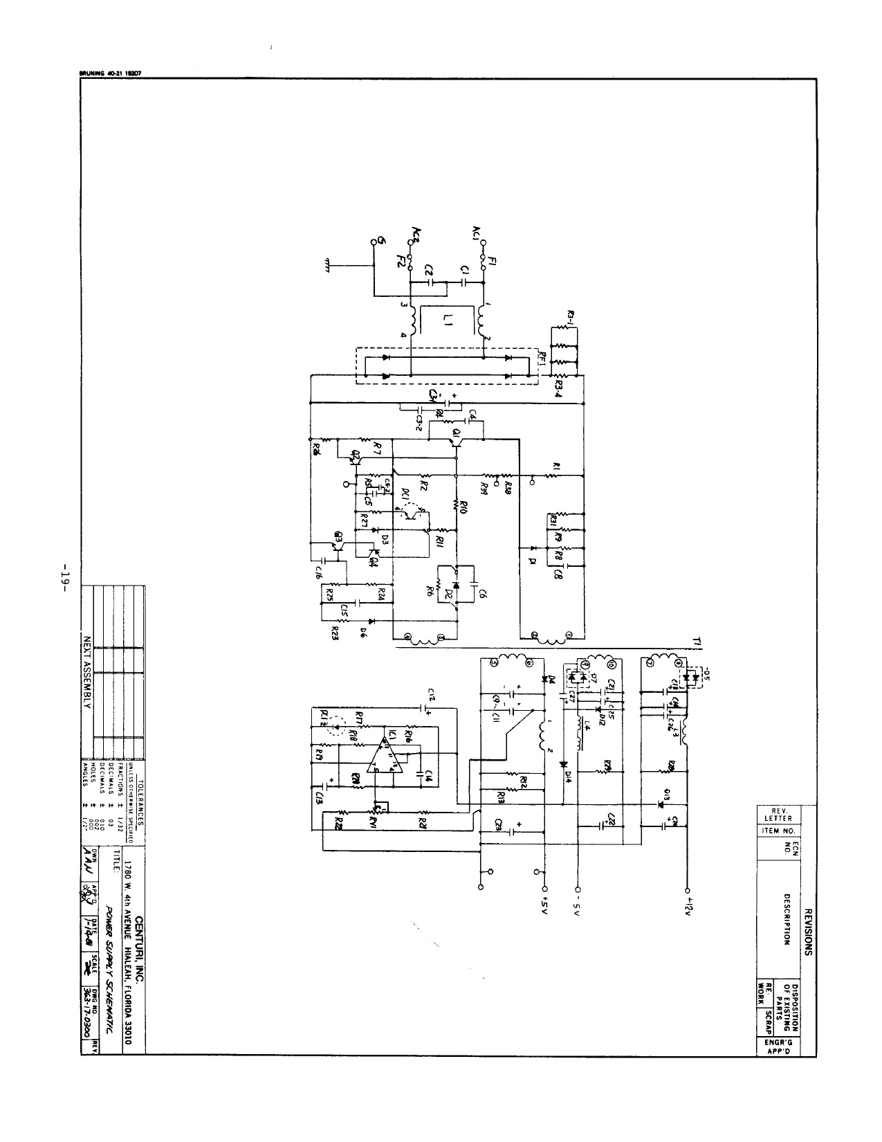
This page is a drawing, shown as the original scan.
REVISIONS REY. LETTER ITEM NO.
DISPOSITION
OF EXISTING {2 0 PARTS |S. RE. [SCRAP] SS FCN
No. DESCRIPTION
NOT USED
mewn 00.21 1207
2 bcerrcom sw wi/or 3 | ReHr com sw c WHITE a }—7esT
wileRy Bik ss |woruseo . WHEL G Guo
a > Maiyeur 7 9 wivaweeeo | 8
_| ANH/BLUE/PUR 2 Nor USED a. a TM IBLUE/OR 10 SLAM SWITCH Nea/vel [Bux uy
WH/YEL /RED 12 esed OT USES Maruzeb WH/BLK/BWE 13 PA couwr i ‘WH/ BLK /BRN 4 [es
N23) WHIBUX/GRN is RIGHT LANE LEFF LAMB WHPBLK/ RED el or useo
1 /BLK/PuR 7 7 WH BAO 18 WHEE, 9 sv, nieve} 20 San
a i; ; 2 |} wor aseo Say 8 ° 2a cuassie GWE i) laaat ol ater ee
“TOTAL, COM METER:
RIGHT COIN LEFT COIN NOT USED
LOCKOUT COL LocKour core (:1001F 80) (MonF1e0)
WIRING DIAGRAM KR, NTUEL MODIFIED, COIN ACCEPTORS (VE, #2002 SERIES (Tul MECH) COIN NOT USED ne
CENTUR: PT No 360-/4-0700 NO, NO. RIGHT COIN SWITCH [er CON SwiTcH NoT used
¢
res ras
CENTUR, INC.
ues = 1780 W. 4th AVENUE HIALEAH, FLORIDA 33010
reacts ¥ vate CIMALS, : 93 COIN DOOR WIRING DIAGRAM NEXT ASSEMBLY i Kan, oe Ee
ABE
RESET
Clock >. 741504 Ye rats 04 alcool rh AY3-8910 S6WO
: (vipeo) ec
Ves
a cs u Ik
id
surea77 19 ~NaEUe v8.
rh oom ae THe eD ok
WD, rok OMT HID,
prick vat)
10K 2424K0 fT)
u RTO
bk
90 eees,)
J, Me3773 + 10k
mn (ee +12V
Mal
AuvIO UT. ica 74 2 ey Voom WY “Ny zm > AY3-8H2 SN76477
24cs10 746500 MB37/3 R 100k kW ik SK joe ’ 230K ¥ 4 ' 12) t
Rik? (Wor $ Pet F120) C16, 27H! TATA CAP, & amuiby ! Woouiy 3
C65 MyLAe CAR (wer specimen) C1098 ! 1000 Mycag capacio€ |
SdR G~cs, nee
Cy Wr (loge) Cz 1000PCH) a 2ME(o-swe> Ga IAro-sove) Gomer, EL CMEM:CAL CONDENSOR ME MYLAa Cam Ri 47K Re 33M RS Zoek Ra are Rs ank Re 75k 7 /o0k Re ze Nove Pay 3-0910 Boren Brut Ves dmb CORAM CAP YBN STALLED
[ASSEMBLY NO. ‘Prop. arvo | ary.
REV. LET. ECN NO. REVISION BY TOLERANCES
HIALEAM, FLORIDA 39016 FRACTIONS DECIMALS 2 PL DECIMALS 3 PL SCHEMATIC ~ ROUTE 16
HOLES HEAT TREAT. FINA
anates BATES 278! PART NO. REV 36610-0000 BEALE
aI 10F8
24 Q-—~—_+sv
Ss 368 av te _ PAETHo| Name ety] a ict [42 pw/ av lee [msl7s | a RI 47K 13 |gesaz | / ° ima j* lea~ol esx | 3 ; | Ri | dma | / 4a
RK
| , 7 | ek | R3 | aKa | | |
| Ro | ERTAL | a | i |
| 220 | CL | a20—%)) | 7) |
7 oe cde ' | r¢ CUR 7 Sed ev bl assea| 1
Re Lomas | 3022-12) 2, Ry RST Re
Re
| Ru | Ke | Po | |
| Res | Ki | % | |
| Ric | a | D | |
| fA | Alig | 4 | |
| Ris | ‘ | 19 24 | Bs |
I) resis ) Yywesse 8 [30007 | wp tooop | cr acy Oo 4 aa __ ‘ac. avo | PROD. aPvD | avy, | ASSEMBLY NO TOLERANCES
| [ | The Obs ea | centuri. | WAL, FLOMBA 3014 |
VE mae — pecimAce sec! i) 68 Sl BOARD SCHEMANK-20UTE 16 a + 03 fRATCS HEAT TREAT. Fins
| Trev. | cow | a | {te [BRR | ]arro | [BATE | [SEALE] | PART NO. | FEV. |
| tr | | REVISION | ov | anette eenos |S [RAM | Be-a/ PSE [32220-0400] |
IQ 2068
This page reads as a drawing: its text was drawn rather than typeset, and comes out in fragments. See the original scan.
26X7 com, 08000], 1000 fa, 1800], 20m] n, 28100 *
| 0 | No | {aio | ||
| q | 9 | 9 | 9 ae | |
| 2 wns | 8 ame | 8 penal | sponap <<" | |
| i. | 72 | Vs | 7 Fla | |
| 6 Ene | é | 6 jf sv | ||
| = | 5 | s | s | |
| a | H | +] | EY | 4 8. |
3300 4 |
| = | 2 | 2 | |||
| é re q CJ O cy | : | 2 | : | : the | |
| ie | ery | one | ° 1708 | ||
| By | By | 87 | i] | ||
| WaiT> | Nd RT | é | 4 | y | a |
| H | 5 | 5 | 5 | ||
| 4 | a | a | 4 | ||
| 3 | 3 | 3 | 3 | ||
| | — | ‘ | 2 | 2 | 2 |
INT 7
| 0 | ° | re) | ° |
= bated
| RET eto! 28 RS | EN | ep Ye |
- Me) Ferre
| AE er FER | SC | Goel |
7rsd2 1 T4LS3e7 3 7mis3z 4 piso ot REgeT>_____24 peer tne ts) . 2708 (1) ABI 280 2 od ABBE EB Bis" son
M4IS3Z 4 centur. macnn, FLonioa 014 Fractions + 92 bea _|___ DEOmALESL 2 008 CPU-2 BOARD SCHEMATIC ~ ROUTE IG
| hours | 3 oo farce | IWeAT TheaT, | Fine |
2 ‘oo | eCN 2 te | i REVISION oy | 2804 seo: = Paw Peice: PES Bee%0-0400 [| -24- 40F8