Food Fight TM-229 2nd Printing
Food Fight (rev 3) (General Computer Corporation (Atari license), 1982) · Technical Manual · 72 pages · 54 sections · original scan
2nd printing
Fr FED FIGHT TM-229
qT
If reading through this manual does not lead to solving a certain maintenance problem, call TELEHELP® at the Atari Customer Service office in your geographical area, as shown below.
WEST and CENTRAL U.S.A. Parts and Service
Atari, Inc. California Customer Service Office 1105 N. Fair Oaks Avenue P. O. Box 427, Sunnyvale, CA 94086 Telex 17-1103 (Monday-Friday, 7:30-4:00 pm Pacific Time) From California, Alaska, or Hawaii @ (408) 745-2900 ee Service from anywhere in the area shown in white toll-free (800) 538-1611
EAST U.S.A. Service only
Atari, Inc. New Jersey Customer Service Office 12A World’s Fair Drive, Somerset, NJ 08873 Telex 37-9347 (Monday-Friday, 7:30-4:00 pm Eastern time) exe From New Jersey (201) 469-5993 exe From anywhere else in this area toll-free (800) 526-3849
EUROPE Parts and Service
Atari Ireland Limited European Customer Service Office Tipperary Town, Ireland Telex 28-165 TIPPERARY TOWN, (Monday-Friday, 9:00-6:00 pm GMT) IRELAND
BS 062-52155
This page carries no recoverable text. It is a drawing or a photograph. See the original scan.
Food Fight
© 1983 by Atari, Inc. All rights reserved. No part of this publication may be reproduced by any mechanical, photographic, or electronic process, or in the form of a phonographic recording, nor may it be stored in a retrieval system, transmitted, or otherwise copied for public or private use, without permission from the publisher. The game play, all graphic designs, this technical manual, its accompanying schematic diagrams, and the display manual are protected by the U.S. Copyright Act of 1976. This Act provides for increased penalties for violating federal copyright laws. Courts can impound infringing articles while legal action is pending. If infringers are convicted, courts can order destruction of the infringing articles. In addition, the Act provides for payment of statutory damages of up to $50,000 in certain cases. Infringers may also have to pay costs and attorneys’ fees, fines up to $25,000, and face an imprisonment of up to one year. Atari will aggressively enforce its copyrights against any infringers. We will use all legal means to immediately halt any manufacture, distribution, or operation of a copy of video games made by us. Anyone who purchases such copies risks forfeiting such a game.
Published by: ATARI, INC, 790 Sycamore Drive P.O. Box 906 Milpitas, California 95035
Printed in the U.S.A. 3M
Notice Regarding Non-ATARI Parts
You may void the game warranty (printed on the inside back cover of this manual) if you do any of the following: © substitute non-ATARI parts in the game © modify or alter any circuits in the game by using kits or parts no¢ supplied by Atari.
This equipment generates, uses, and can radiate radio frequency energy and if not installed and used in accordance with the instruction manual, may cause interference to radio communications. It has been tested and found to comply with the limits for a Class A computing device pursuant to Subpart] of Part 15 of Federal Communications Commission(FCC) Rules, which are designed to provide reasonable protection against such interference when operated ina commercial environment. Operation of this equipment in a residential area or modification to this equipment is likely to cause interference in which case the user, at his own expense, will be required to take whatever measures may be required to correct the interference. If you suspect interference from an ATARI® game at your location, check the following:
- Allgreen ground wires in the game are properly connected as shown in the game wiring diagram.
- The power cord is properly plugged into a grounded three-wire outlet. e = The game printed-circuit board(s) (PCB) is properly installed within the Electromagnetic Interference (EMI) cage. ¢ The EMI Shield PCB is properly installed and connected in series with the game PCB harness. e All filter capacitors required on the EMI Shield PCB are properly soldered in place. If you are still unable to soive the interference problem, please contact ATARI Customer Service. See the inside front cover of this manual for service in your area. Food Fight
iii
Food Fight
Table of Contents
1 Set-Up Procedures A. Howto Use This Manual. . . 1-L B. Game Overview. ...... 1-4 C. Installation Specifications . 1-4 D. Inspectingthe Game . . se 1-4 E. Voltage-PlugSelectionandFuses . 1-5 F, SwitchLocations ..... oe 1-6
- Power On/Off Switch . 1-6
- Utility Panel Switches . 16
- Option Switches 16 G. Selecting the Coin and Credit Options 1-6
2 Self-Test Procedure A. Self-Test Display. 2-2 B. Self-Test Menu sane 2 C. Selectingthe Options... 00.6... eee ete eee 2-6 3 Iustrated Parts Lists Partslists beginon page ... 2.6... 66 eee eee ee eee eee 3-2
Appendix A GimbalJoystick Maintenance ... 0.0.6... ccc eee eee Al
Figure 1-1 Figure 1-2 Figure 1-3 Figure 1-4 Figure 2-1 Figure 2-2 Figure 2-3 Figure 2-4 Figure 2-5 Figure 2-6 Figure 2-7 Figure 3-1 Figure 3-2 Figure 3-3 Figure 3-4 Figure 3-5 Figure 3-6 Figure 3-7 Figure 3-8 Figure 3-9 Figure 3-10 Figure 3-11 Figure 3-12
Figure 3-13 Figure 3-14 Figure 3-15 Figure 3-16 Figure A-1
Table 1-1 Table 1-2 Table 2-1 Table 2-2 Table 2-3 Table 2-4 Table 2-5 List of Illustrations
Game Overview, US-BuiltGame ... 0.0.0. eee 1-2 Game Overview, Ireland-BuiltGame .. . 13 Voltage-Selection Plug and Fuse Locations 15 Option Switch Locations 16 Main Self-Test Menu . . 23 Hardware TestsMenu . 23 Switch Test Display... . 2-4 Color Pattern 2-4 Convergence Pattern . 2-4 Statistics Display... .. . 2-5 Options Display. . 2-6 Cabinet- -Mounted Assemblies, US-Built Game . 3-2 Cabinet-Mounted Assemblies, Ireland-Built Game. ae 3-4 Control Panel Assembly. . . Gimbal Joystick Assembly. . . Fluorescent Tube and speaker, Us. BuiltGame se Fluorescent Tube and Attraction Panel, Ireland-Built Game .. 3-12 Video Display, US-Built Game Video Display, Ireland-BuiltGame .. . . Utility Panel Assembly. ........... Vertically Mounted Coin Door. : American-Made Coin Door. .... Electromagnetic Interference (EMI) Cage Assembly and BEEN Hardware ....... : EMIShield PCB Assembly. .... . - Food FightGame PCB .......... : Regulator/Audio!I PCB Assembly. . . . bee Color Raster-Scan Power Supply Assembly. . . Disassembling the Pivot Shaft Assembly
List of Tables
Installation Specifications «6.6.0... 0.0 eee ce eee 1-4 Switch Settings for Price and Bonus Options ..... . 1-7 Playfield RAM Locations 2-2 Program RAM Locations 2-2 Program ROM Locations . 2-2 Sound Chip Locations . 2-4 Option Settings 2-6 Food Fight
Food Fight
vi
Safety Summary
The following safety precautions apply to all game operators and service personnel. Specific warnings and cautions will be found throughout this manual where they apply.
WARNINGS
Properly Ground the Game. Players may receive an electrical shock if this game is not properly grounded! To avoid electrical shock, do not plug in the game until it has been inspected and properly grounded. This game should only be plugged into a grounded 3-wire outlet. If you have only a 2-wire outlet, we recommend you hire a licensed electrician to install a grounded outlet. Players may receive an electrical shock if the control panel, video display, EMI cage, fluorescent light assembly, and utility panel are not properly grounded! After servicing, check that the green ground wire or grounding clip for each assembly is firmly attached. Only then should you lock up the game. AC Power Connection. Before connecting the game to the AC power source, verify that the proper voltage-selection plug is installed on the game’s power supply. Disconnect Power During Repairs. To avoid electrical shock, disconnect the game from the AC power source before removing or repairing any part of the game. Discharge High Voltage from the Video Display. When removing or repairing the video display, extra precautions must be taken to avoid electical shock. High voltages may exist within the display circuitry and cathode-ray tube (CRT) even after power has been disconnected. Do not touch internal parts of the display with your hands or with metal objects held in your hands! Always discharge the high voltage from the CRT before servicing this area of the game. To discharge the CRT: Attach one end of a large, well-insulated, 18-gauge jumper wire to ground. Momentarily touch the free end of the grounded jumper to the anode by sliding it under the anode cap. Wait two minutes and discharge the anode again. Use Only ATARI Parts. To maintain the safety integrity of your ATARI game, use only ATARI authorized parts when repairing the game. Use of non-ATARI parts or modifications of the game circuitry may adversely affect the safety of your game, void the warranty, and injure you or your players. Handle Fluorescent Tube and CRT With Care. If you drop a fluorescent tube or CRT and it breaks, it will implode! Shattered glass can fly six feet or more from the implosion. Use the Proper Fuses. To avoid electrical shock, only use replacement fuses that are specified in the parts list for this game. Replacement fuses must match those replaced in fuse type, voltage rating, and current rating. In addition, the fuse cover must be in place during game operation.
Properly Attach All Connectors. Before turning on the game for the first time, make sure that all connectors are properly attached. Make sure that the connectors on each PCB are properly plugged in. Note that they are keyed to fit only one way. If they do not slip on easily, do not force them. A reversed connector may damage your game and void the warranty.
A. How to Use This Manual
This manual, written for game operators and service technicians, describes the Food Fight™ game. The manual contains information about both the Ireland- and US-built games, Wheneyer information is unique to the Ireland-
built game, this symbol appears: *
‘Whenever information is unique to the US-built game, this symbol appea:
Chapter 1 contains game specifications, inspection procedures, voltage plug and fuse information, switch locations, and option information. Chapter 2 contains self-test procedures. Chapter 3 contains illustrated parts lists. Figures 3-1 and 3-2 illustrate the US-built and the Ireland-built game cabinet. Italicized type on these figures refer you to other places in the manual for information about specific cabinet parts. Schematic diagrams of the game circuitry are includedas a supplement to this manual.
Chapter 1
Set-Up Procedures
Fluorescent Tube & Speaker See Figure 3-5
Video Display | See Figure 3-7 3
Control Panel See Figure 3-3 Gimbal Joystick See Figure 3-4
Utility Panet See Figure 3-9
Coin Door Assy.- See Figures 3-10 & 3-11
Do not plug in the game until it has been Inspected. This game should only be connected to a grounded 3wire outlet. If you have only a 2-wire outlet, we recommend you hire a licensed electrician to install a grounded outlet. Players may receive an electrical shock If this game is not properly grounded! Self-Test Switch
Power Supply See Figure 3-16 Food Fight
ame Identification Label x
7 ‘Access Panel
EMI Cage See Figure 3-12 Game PCB* See Figure 3-14
EMI Shield PCB See Figure 3-13
Regulator!
Audio II PCB x
See Figure 3-15
Power On/Oft Switch
Item with a serial number label
Figure 1-1 Game Overview—US-Built Game
Food Fight Set-Up Procedures
Fluorescent Tube & Attraction Panel See Figure 3-6 * Game Identification Label
Video Display See Figure 3-8
Access Panel
Control Panet See Figure 33 Gimbal Joystick See Figure 3-4 See Figure 3-14
Coin Door See Figures 3-10 & 3-11 Regulator! Audio Il PCB See Figure 3-15
Utility Panel See Figure 3-9
Power On/Off Switch
Figure 1-2 Game Over view—Ireland-Built Game
1-3
Set-Up Procedures Food Fight
B. Game Overview D. Inspecting the Game
Food Fight hero, Charley Chuck, gets points by eating his Please inspect your game carefully to ensure that it was ice cream cone before it melts. To do this, he must fight off delivered to you in good condition. Oscar, Angelo, Jacques, and Zorba, the four chefs who rise from holes and throw food at him. When Chuck eats the cone, the ice-cream flavor changes and the game difficulty WARNING
increases Shock Hazard
; . To avoid electrical shock, do not plug in the All major parts of the US-built Food Fight game are illus- game until the procedures in Sections D and E trated in Figure 1-1. All major parts of the Ireland-built have been completed! game are illustrated in Figure 1-2. Do not touch internal parts of the display with your hands or with metal objects held in your hands!
:
Cc. Installation 1, Examine the exterior of the game cabinet for dents,
Specifications chips, or broken parts.
- Remove the screws from the rear access panel. Table 1-1 describes the physical, electrical, and environ- Unlock and open this panel and the coin door; inspect mental specifications of the game. the interior of the game as follows: a. Ensure that all plug-in connectors (on the game Table 1-1 Installation Specifications harnesses) are firmly plugged in. Replug any connectors found unplugged. Do not force connec-
| Power Consumption | 200 W | tors together. The connectors are keyed so they |
only fit in the proper orientation. A reversed edge ‘ ° °
| Temperature | Oto +38° | C(+32 to +100° | F) | connector may damage a PCB and will void |
| Humidity | Not to exceed 95% relative | “your warranty, | ||
| Line Voltage | 100 to 240 VAC | b. | Ensure that all plug-in integrated circuits on the |
US-Built Cabinet PCB are firmly plugged into their sockets.
| Width | 62.5 cm (25.5 in.) | c. | Remove the tie-wrap that secures the coiled |
- power cord inside the cabinet. Inspect the power
| Depth | 86 cm (34 in.) | cord for any cuts or dents in the insulation. Repair |
| Height | 181.5 cm (72 in.) | or replace it as required. Place the square strain- |
Treland-Built Cabinet relief plate in the wood slot at the bottom of the
| Width | 60 cm (24 in.) | 4 | eat panel ee | tt | asth |
. Inspect major subassemblies, such as tl wer Depth 68 cm (27 in.) Ps aloe =p supply, control panel, video display, and EMI
Height 170 cm (67 in.) cage. Make sure they are mounted securely and
that the green ground wires are connected.
Food Fight
E. Voltage-Plug Selection
and Fuses
The power supply in your game contains six fuses. When you replace a fuse, use the identical type fuse with the same electrical rating (see Figure 1-3). This power supply operates on the line voltage of many countries. The power supply comes with either one, two, or three voltage-selection plugs. Plug voitages and wire
Voltage-Selection Plug
FUSE F2 (4 A, 250 V)
FUSE F3 (20 A, 32 V) FUSES F4-F6 (4 A, 250 V) Set-Up Procedures
colors are 100 VAC (violet wire color), 120 VAC (yellow wire color), 220 VAC (blue wire color), and 240 VAC (brown wire color). See Figure 1-3 for placement of the voltage-selection plug. Before plugging in your game, check your line voltage. Next, check the wire color on the voltage-selection plug. Make sure the voltage-selection plug is correct for the voltage of your location. Now plug the game into a grounded 3-wire outlet.
FUSE Ft (7 A, 250 V) FUSE F1 (4A, 250 vy
Figure 1-3 Voltage-Selection Plug and Fuses
Set-Up Procedures
FE. Switch Locations
Power On/Off Switch The power on/off switch is located on the back of the cabinet on the lower left side (see Figure 1-1 or 1-2).
Utility Panel Switches
The volume control, coin counter(s), self-test switch, and auxiliary coin switch are on the utility panel. The utility panel is located inside the upper coin door (see Figure 1-1 or 1-2). The volume control adjusts the level of sound produced by the game. The coin counter(s) records the number of coins entered into the game. The self-test switch initiates the self-test operating mode. The auxiliary coin switch is used to credit the game without activating a coin counter.
Option Switches
Option switches for game price selection are on the game printed-circuit board (PCB) at location SW1 (see Figure 1-4).
G. Selecting the Coin and Credit Options
Settings of the game coin and credit option switches are explained in Table 1-2. Options preset at the factory are shown by the «4 symbols. However, you may change the settings according to your individual needs.
Game PCB Food Fight
To verify other option selections, check the self-test display that appears when you turn on the game. Then, verify the option switch settings on the self-test display as described in Chapter 2, Checking Option Settings. Table 1-2 describes the settings for the DIP switch at location SW1. This switch selects the game coin and credit options available for the left and right coin mechanisms. The basic unit of measurement is a coin worth $.25 or 1 DM. Thus, if you have a2 DM/1 DM coin door with two coin counters, set switch 5 at location $SW1 to on. Then, different denominations are counted on the two coin counters.
swi
OFF 1-8
Figure 1-4 Option Switch Location
1-6
Food Fight Set-Up Procedures
Table 1-2 Switch Settings for Coin and Credit Options
3 4 5 Settings of 8-Toggle Switch on Game PCB (at SW1) Z 6 Option
Off Off Off On
On On
On Off
On Off
On On
Off On Off On Off On Off On
Off On Off Off On On Off Off
On On Off Off Off Off On On
On On Free Play 1 coin 2 credits 1 coin 1 credit <4 2 coins 1 credit
Right Coin Mechanism 1 coin } credit <4 1 coin 4 credits 1 coin 5 credits 1 coin 6 credits
Left Coin Mechanism 1 coin 1 credit <4 1 coin 2 credits No bonus coins <4 No bonus coins For every 4 coins, logic adds 1 more coin For every 2 coins, logic adds } more coin For every 5 coins, logic adds 1 more coin For every 3 coins, logic adds 1 more coin
No bonus coins No bonus coins
~< Manufacturer's recommended settings
1-7
This page carries no recoverable text. It is a drawing or a photograph. See the original scan.
Self-Test Procedure
This game will test itself and provide data to show that the game circuitry and controls are operating properly, Seiftest data is presented visually on the player LEDs and the video display, and audibly through the speakers. No additiona! equipment is required. We suggest that you perform a self-test when you first set up, each time you collect money, change the game options, or suspect game failure.
Chapter 2
Self-Test Procedures
A. Self-Test Display
When the power switch is turned on, Food Fight enters the automatic selftest mode, which tests playfield RAM, program ROM, and non-volatile RAM (NVRAM). At the beginning of these tests, both the one-player and two-player LEDs are lit. (This is so that the success or failure of the tests can be indicated even if the messages cannot be displayed on the monitor.) If the playfield RAM and program RAM are working, then the one-player LED turns off and the message RAM OK is displayed on the screen, If the playfield RAM fails, the one-player LED flashes one through four times followed by a pause. The playfield RAM number displayed corresponds to the board location of the faulty chip as shown in Table 2-1.
Table 2-1 Playfield RAM Locations
Playfield RAM
Number Board Location
1 3K a 3L 3 3M 4 3N
If the program RAM fails, the one-player LED remains on,
and the number of the bad chip is displayed. The program
RAM number corresponds to the board location of the faulty chip as shown in Table 2-2.
Table 2-2. Program RAM Locations
Program RAM
0 8B 1 8A 2 OB 3 9A
After the RAM is checked, the checksums for program
ROMare verified. Ifall ROMs check out correctly, then the
two-player LED is turned off and the message ROM OK is displayed. If there are faulty chips, then the ROM number
2-2 Food Fight
of each faulty chip is displayed. The ROM number corresponds to the board location of the faulty chip as shown in Table 2-3.
Table 2-3 Program ROM Locations
ROM Number Board Location
9C 8C 9D 8D 9E 8E OF 8F MAU REN ERS
After the program ROM is checked, the checksums for the NVRAM are verified. If all sections of the NVRAM check, then the message NVRAM OK is displayed. If any section of NVRAM fails, then the name of the faulty section is displayed and factory values from program ROM are used instead of the values from that section. If playfield RAM, program RAM, and NVRAM check out correctly, Food Fight goes into the attract mode after five seconds. If NYRAM fails, the game will go into the attract mode when the THROW button has been pushed. The five sections of NVRAM are as follows: STATISTICS holds the values for the statistics display (see the description under Self-Test Menu). These values can be reset using the options menu. TIME AND CREDITS holds the total time the machine has been on, and the total number of credits. These appear at the bottom of the statistics display and cannot be reset. HIGH SCORES holds the player initials, scores, and levels achieved for the top three high-scoring games. These values appear at the top of the high-score table during the attract mode and can be reset using the options menu. OPTIONS holds the current settings for the game options, which can be displayed and/or changed using the options menu. JOYSTICK VALUES holds the maximum and minimum. values for the analog joystick. See the description of Joystick Calibration under the TESTS option of the selftest menu.
Food Fight
B. Self-Test Menu
Food Fight has a menu-driven self-test mode which is entered by turning the self-test switch on. Turning the selftest switch off at any time during self-test mode causes the game to return to the attract mode. Immediately after the self-test switch is turned on, the main self-test menu appears as shown in Figure 2-1. Three choices are available—TESTS, STATISTICS, and OP- TIONS. Move the joystick up or down to change the current selection, which is displayed in red. Push the THROW button to select.
SELF-TEST
MOVE JOYSTICK TO CHANGE PUSH THROW TO SELECT
TESTS STATISTICS OPTIONS
TURN SELF-TEST SWITCH OFF TO END
Figure 2-1 Main Self-Test Menu
Hardware Tests
Selecting TESTS causes the hardware test menu to appear as shown in Figure 2-2. There are five choices available— JOYSTICK CALIBRATION, SWITCH TEST, COLOR PATTERN, CONVERGENCE PATTERN, and SOUND TEST. Use the joystick and THROW button to select any option. Push the one-player start button to return to the main self-test menu.
Self-Test Procedures
TESTS PusH START 1 TO ENO TESTS
JOYSTICK CALIBRATION SWITCH TEST COLOR PATTERN CONVERGENCE PATTERN SOUND TEST
Figure 2-2 Hardware Tests Menu
JOYSTICK CALIBRATION resets the joystick minimum and maximum values, and should be used whenever the NVRAM or joystick is replaced, Hold the joystick steady for a full five seconds in each direction (left, right, up, down) to store new values. Push the oneplayer start button to return to the TESTS menu.
2-3
Self-Test Procedures
SWITCH TEST displays the state of the control panel switches, the joystick values, the coin inputs, and the dual-inline-package (DIP) switches as shown in Figure 2-3. Aone (1) indicates that the switch is on, and a zero (0) indicates it is off. All eight bits are displayed for each direction of the joystick. Push both the one- and two-player start buttons to end this test. See Chapter 1, Selecting the Options, for information on the settings of the DIP switch located on the game PCB.
Figure 2-3 Switch Test Display
COLOR PATTERN displays all 256 Food Fight colors ona 16-by-16 grid of blocks in the center of the screen as shown in Figure 2-4. Use this display to check for color adjustment. Press the one-player start button to end this test. The colors are properly adjusted when the background is black and each colored block is distinguishable from those around it. Food Fight has four blue levels, eight green levels, and eight red levels. These are overlayed to display the color grid as follows: ¢ Blue is displayed in four quadrants with level 0 (no blue) in the lower left quadrant, level 1 in the lower right quadrant, level 2 in the upper left quadrant, and. level 3 (intense blue) in the upper right quadrant.
- Green is displayed in sixteen horizontal bars, two bars for each level, with level 0 (no green) bars at the center, level 7 (intense green) bars across the top and bottom, and intermediate levels in between. © Red is displayed in sixteen vertical bars, with level 0 (no red) bars at the center, level 7 (intense red) bars at the right and left, and intermediate levels in between.
2-4 Food Fight
Figure 2-4 Color Pattern
CONVERGENCE PATTERN a white crosshatch pattern
appears on the screen as shown in Figure 2-5. Use this pattern for convergence (see the raster-scan video display manual for a detailed procedure). Push the one-player start button to end this test.
Figure 2-5 Convergence Pattern
SOUND TEST tests the twelve channels of the three Custom Audio sound chips. As the channel number is displayed, the test sound is played. The test continues to cycle through the channels until the one-player start button is pressed to end the test. The channels correspond to the three Custom Audio chips as shown in Table 2-4.
Food Fight
Table 2-4 Sound Chip Locations
Chip No. Board Location Channels
| 1 | 11K/L | 5,6, 11, 12 |
| 2 | 11L/M | 1,2,7,8 |
| 3 | 11N | 3,4, 9, 10 |
Selecting the Statistics This is the second selection on the main self-test menu. Selecting STATISTICS causes the game statistics display to appear as shown in Figure 2-6. Press the one-player start button to end this test.
| StatTistics | Pusn start | 1 | TO END |
NUMBER OF GAMES
7)
90:90:00 00:50:30
Figure 2-6 Statistics Display
The totals on the display are those accumulated since the Statistics were last reset. All statistics (except the last two) can be reset using the CLEAR VALUES, and STATISTICS selections of the options menu. All times on the display are
shown as hours:minutes:seconds. The following statistics
are displayed: NUMBER OF GAMES reads the number of one-player
games, the number of two-player games (increased by one
for each two-player game), and the total number of games. COIN COUNT reads the number of coins inserted through each of the right and left coin mechanisms. CREDITS reads the number of paid credits, free credits (entered using the auxiliary coin button), and the total credits since the statistics were last reset. BONUS MEN EARNED reads the number of bonus lives (extra Chucks) earned at the first stage at higher stages using level select, and the total. Italso shows the percentage of games played in which at least one bonus life was earned. Self-Test Procedures
AVERAGE TIME reads the average times between credits and games. LONG GAME reads the longest time a player was able to play on one credit. TOTAL TIME ON reads the total time the game has been turned on since the statistics were last reset. IN PLAY MODE reads the percentage of time the game has been in play mode (as opposed to attract mode) since the statistics were last reset.
TOTAL TIME reads the total amount of time the game has
been turned on. TOTAL CREDITS reads the total number of credits.
C. Selecting the Options
Selecting OPTIONS, the third selection on the main selftest menu, causes the options display shown in Figure 2-7 to appear. Use this display to view or change game option settings, or to clear the high scores or statistics. Push the THROW button to cycle through values on the current row (indicated in red), Change the current row using the joystick or the two-player start button. Push the one-player start button to end this display and make the displayed option settings the current settings.
OPTIONS MOVE JOYSTICK TO CHANGE ROW PUSH THROW TO CHANGE SETTINGS PUSH START | TO ENO « n <z mi ACEC Mme mOZW<<OBT Gor BZ OPDO mn © t i S t
Lu ul a L cot S I c = PCO OOb~mm
° r n wrp o O89 I< AWM ZRSBANTO
> om
Eo pa
Figure 2-7 Options Display
Self-Test Procedures
To restore settings or to clear values, select the desired row and push the THROW button. RESTORED or CLEARED is then displayed. The options and settings available are listed in Table 2-5.
Description of Option Terms
LIVES PER GAME sets the initial number of lives (Chucks), not including bonus lives, given for each credit. DIFFICULTY sets the game difficulty at levels 4 and above. Level 1 is easy, level 5 is hard.
BONUS STAGES. sets the scores at which the first or subsequent bonus lives are awarded. Additional bonus lives are awarded when the score reaches a multiple of the higher bonus stage. For example, when the factory settings of 25,000 and 100,000 are in effect, bonus lives are awarded at 25,000; 100,000; 200,000; 300,000; etc. The first bonus stage may not exceed the second bonus stage. If the two are equal, only one bonus life is awarded when the score reaches the first bonus stage. For example, if both stages are set to 25,000, then bonus lives are awarded at 25,000; 50,000; 75,000; etc. Either one or both bonus stages can be turned off. LEVEL SELECT BONUS if turned on, awards bonus lives when the player uses level select to start the game at or above level 10. An extra life is awarded for starting at Food Fight
levels at or above every multiple of 10, with one additional life at level 125. For example, ten bonus lives would be awarded for starting at level 103. These bonus lives are given at the start of the game in addition to the LIVES PER GAME. The level at which bonus lives are earned and the current number of lives awarded are displayed with Chuck heads during level select.
LEVEL SELECT MODE effects how the level select feature is handled. There are four possible settings: *¢ NORMAL allows the player to select a starting level if the last game ended less than 15 seconds before, and if. the maximum level achieved in the last game was greater than level one. If both of these cases hold, the player is allowed to select a starting level up to the maximum level achieved in the last game.
*® CONSTANT always allows the player to select a starting level up to at least level 9. If the last game ended less than 15 seconds before, the player is allowed to select up to the maximum level achieved in the last game.
- DEMO always allows the player to select up to the maximum Food Fight level, for example, level 125. This setting would probably not be used for a game out on location, but is useful to demonstrate the performance of the game at high levels. © OFF causes no level select display to occur.
ATTRACT SOUNDS disables the attract mode sounds if in the OFF setting. COIN COUNTERS causes both coin mechanisms to drive the same coin counter if in the ONE setting.
Table 2-5 Option Settings
Option Settings Available Factory Setting
| Lives per game | 2-5 | 3 |
| Difficulty | 1-5 | 2 |
| First bonus stage | Off, 5000-1,000,000. | 25,000 |
| Higher bonus stage | Off, 5000-1,000,000 | 100,000 |
| Level select bonus | Off/On. | On |
| Level select mode | Normal, constant, demo, off | Constant |
| Attract sounds | Off/On. | On |
| Language | English, German, Spanish, French | English |
| Cocktail mode | Off/On. | Off |
| Coin counters | One/Two | One |
2-6
Food Fight
RESTORE SETTINGS resets the displayed option settings to one of the following:
Remember that the high scores and statistics will NOT be affected if the options menu is ended by turning off the self-test switch.
CLEAR VALUES resets the high-score table to its factory setting and resets to zero all the items on the statistics display, except for the TOTAL TIME and TOTAL CRED- ITS. The clear takes effect when the options menu is ended using the one-player start button. CURRENT displays the option settings in effect before the option menu was entered. FACTORY displays the option settings from the program ROM. Self-Test Procedures:
This page carries no recoverable text. It is a drawing or a photograph. See the original scan.
Illustrated Parts Lists
This chapter provides information you need to order parts for your game. Common hardware (screws, nuts, washers, etc.) has been deleted from most of the parts lists. However, there is a parts list for the hardware to mount the game PCB and Regulator/Audio IT PCB to the cabinet. The PCB parts lists are arranged in alphabetical order by component. Each component subsection is arranged alphanumerically by reference designator. Other parts lists are arranged alphanumerically by Atari part number. In these parts lists, all A-prefix numbers come first. Following these are numbers in sequence evaluated up to the hyphen, namely 00- through 99-, then 000598- through approximately 201000-. When ordering parts, please give the part number, part name, number of this manual, and serial number of your game. This will aid in filling your order rapidly and correctly. We hope the results will be less downtime and more profit from your game. Atari Customer Service numbers are listed on the inside front cover of this manual.
Chapter 3
Illustrated Parts Lists Food Fight
Manuals, Schematics, & Self- Test Label— See parts list on following page
arose rade el 037332-01 17a034024 (Vent. grille) (T-Molding)
A039735-01 . (Cabinet assy.)
Video Display x{ZZZ_. See Figure 3-7 03741201 —= (Display shield) A038881.01 | (Lock)
= 037419-02 178013-001. (Access panel) (Latch) |
Gimbal Joystick - See Figure 3-4 EMI Cage Control Panel See Figure 212 ont al Game PCB See Figure 38 See Figure 3-14
Utility Panel Assy. EMI Shield PCB See Figure 3-9 See Figure 3-13
A039909-01 cot (Main harn. assy.) in Door See Figures 3-10 & 3-11 Regulator! Audio II PCB 038091-01 See Figure 3-15 (Coin bi aZ Bante | ‘A039910-01
seni pi (Power harn. assy.) (Coin box enclosure) 178048-001 SS) (Caster) o
Power Suppl (Power ono ‘A037453-03 See Figure 3-16 switch assy.) (Power cord)
009992.01 78-3201 (Onioff switch cover) (Glide)
Figure 3-1 Cabinet-Mounted Assemblies US-Built Game A039734-01 A
3-2
Mlustrated Parts Lists Food Fight
Cabinet-Mounted Assemblies Parts List
Part No. Description
A037453-03 A037470-01 A038881-01 A039735-01
A039909-01 A039910-61
SP-229 ST-229-01 TM-160
TM-229
78-3201 009992-01 036495-01 037332-01
037419-02 038091-01 038870-01 039752-01
178013-001 178034-024 178048-001 Strain-Relief Power Cord (U.S. and Canada) Power On/Off Switch and Mounting Plate Assembly Lock Assembly (for tear access panel) Acceptable substitute is part no. A038881-03 Cabinet Assembly (includes glides and PCB retainers, but not the rear access panel)
Main Harness Assembly Power Harness Assembly
The following four items are technical information supplements to this game: Food Fight Schematic Package Food Fight Labe] with Self-Test Procedure and Option Switch Settings Service Manual for 19-Inch Electrohome Color Raster Display (use with part no. 92-049) Acceptable substitute is TM- 220, for use with part no. 139003-1004 Food Fight Operators Manual with Illustrated Parts List
Adjustable Glide Power On/Off Switch Cover Speaker Grille (not shown) Ventilation Grille
Rear Access Panel (does not include lock) Molded Coin Box Coin Box Enclosure Video Display Shield
Spring Draw Latch ¥%-Inch Black Plastic T-Molding 2-Inch Rigid Caster
Illustrated Parts Lists. Food Fight
Manuals, Schematics, & Self-Test Label— See parts list on following page
Fluorescent Tube & Attraction Panel See Figure 3-6
038992-01 (Display shield) 037332-01 (Vent. grille)
Video Display — See Figure 3-8 VA ,
- J 178013-001 SS (Latch) A038881-01 (Lock)
036891-01 (Speaker grille) © 038976-02
(Speaker) " Gimbal Joystick ‘See Figure 3-4 Game PCB See Figure 3-14 Coin Door Assy. See Figures 3-10 & 3-11
A039899-01 038781-01 (Main harn. assy.) Utility Panel Assy. eine See Figure 3-9 Regulator! Audio || PCB See Figure 3-15
A040000-01 178034-024° trMouing) (Power harn. assy.)
A037784-03 (Power cord) 038091-01 x * (Coin Box) 4 78-3201 x (Glide)
Power Supply See Figure 3-16
037470-01 (Power on/off & switch assy.) 009992-01 (On/off switch cover)
Figure 3-2 Cabinet-Mounted Assemblies Ireland-Built Game A040005-02 A
Food Fight Illustrated Parts Lists
Cabinet-Mounted Assemblies Parts List
Part No. Description
A03 7470-01 Power On/Off Switch & Mounting Plate Assembly A037784-03 Strain-Relief Power Cord (United Kingdom, Ireland, Lebanon, Saudi Arabia, India, Hong Kong, Singapore, Egypt, Nigeria, Republic of South African, Zimbabwe) A038881-01 Lock Assembly (for rear access panel) A039999-01 Main Hainess Assembly A040000-01 Power Harness Assembly ‘A040006-01 Cabinet Assembly (includes glides and PCB retainers, but not the rear access panel)
The following five items are technical information supplements to this game: SP-229 Food Fight Schematic Package $T-229-01 Food Fight Label with Self-Test Procedure and Option Switch Settings TM-160 Service Manuai for 19-Inch Electrohome Color Raster Display (use with part no. 92-049) or TM-201 Service Manual for 19-Inch Wells Gardner Color Raster Display (use with part no. 92-055) TM-229 Food Fight Operators Manual with Illustrated Parts List
72-6810S #8 x YyInch Cross-Recessed, Pan-Head Screw 78-3201 Adjustable Gli 009992-01 Power On/Off Switch Cover 034536-02 Foam Pad (not shown)
03689 1-01 Speaker Grille 037332-01 Ventilation Grille 038976-02 Rear Access Panel (does not include lock) 038091-01 Molded Coin Box 038781-01 Coin Box Enclosure 038992-01 Video Display Shield 148001-013 Speaker 175004-708, #8 Flat Fiber Washer
178013-001 Spring Draw Latch 178034-024 %4-Inch Black Plastic T-Molding
Illustrated Parts Lists Food Fight
Players may receive an electrical shock if this control panel is not HORIZONTAL POTENTIOMETER properly grounded! After servicing any parts on the panel, make RED sure that the ground wire is timmly attached to the metal tab on VIOLET the inside of the control panel.
BLACK VERTICAL POTENTIOMETER 75-9910NO 75-5520B ina (Bot) BLACK
BLUE 160013-001 (Leaf switch & button holder) RED
177010-244 (Locknut) 62-039 (LED switch)
75-07020 (Washer) 036895-01 (Switch bezel) A039911-01 (Harness)
04001201 (Control panel * (Control pane! : with deeal with decal) 039749-04 039749-04 (Decal—not shown) (Decal-not shown) 039744-01 040013-01 (Contro! panel) (Control panel)
Figure 3-3 Control Panel Assembly US-Built Game A039746-01 A Ireland-Built Game A040011-01 A
Food Fight Illustrated Parts Lists
Control Panel Assembly Parts List
Part No. Description
A039745-01 78-6900402 039744-01 039749-04
A040012-01 039749-04 040013-01 179125-001
A038838-02 A039911-01 62-039 75-07020
75-5520B 75-9910NO 036895-01 160013-001
177010-244 178030-007 US-Built
Control Panel with Decal Vinyl Foam Single-Coated Adhesive Tape, 4-Inch Wide x ¥-Inch Thick (24 inches required) Control Panel Control Panel Decal (not shown)
Ireland-Built
Control Panel with Decal Control Panel Decal (not shown) Control Panel Grounding Terminal (not shown)
US- and Ireland-Built
Gimbal Joystick Assembly Control Panel Harness Assembly SPDT Momentary Pushbutton Start Switch with Red Light-Emitting Diode #% Steel Flat Washer
#%-20 x 1¥%4-Inch Black Carriage Bolt #% x 11 Stamped Nut Black Molded Switch Bezel Leaf Switch and Button Holder (leaf switch only is part no. 160012-001)
#'4-20 Hex Locknut Yellow Pushbutton Assembly
3-7
Illustrated Parts Lists Food Fight
036952-01 | \ (Housing) | 4 ne (Screw) 036963-01 ' / (Slide plate) 036954-01 (Mounting plate) 036953-01 1 eT (Square control plate) S
(Shaft)
036279-03 (Pivot ball) —~
i 73-21224 (Pin)
A037853-01 (Bellows)
036955-01 (Bellows cap}
75-07020 (Flat washer), 75-010S, | (Washer)
75-9408 1 (Hex nut)
036957-01 (Linkage)
036956-01 (Inner gimbal) (Resistor
. See Appendix A for lubrication (Outer gimbal) information,
Figure 3-4 Gimbal Joystick Assembly A038838-02 A
3-8
Food Fight Illustrated Parts Lists
Gimbal Joystick Assembly Parts List
Part No. Description
A037853-01 Bellows Assembly A038839-01 Pivot Shaft Assembly (includes pivot ball, pivot shaft and slotted pin) 19-9026 5kQ, +20%, 2% W Variable Resistor (acceptable substitute is part no. 119000-502) 72-5240 #10-32 x 2'%-Inch, Zinc-Plated Steel Machine Screw
72-8406 #4-40 x ¥,Inch Socket-Head Steel Machine Screw 73-21224 o-Inch Diameter x 1¥%-Inch Long Slotted Pin 75-0108, #10 Plat Zinc-Plated Steel Washer 75-07020 YeInch Interior Diameter Special Flat Washer
75-9408 #10-32 Self-Locking Hex Nut 036279-03 Pivot Ball 036952-01 Pivot Ball Housing (two required per handle) 036953-01 Square Control Plate
036954-01 Mounting Plate 036955-01 Bellows Cap 036956-01 Inner Gimbal 036956-02 Outer Gimbal 036957-01 Gimbal Linkage 036963-01 Slide Plate 038842-01 Pivot Shaft 039940-01 Pivot Ball Knob 178027-001 Nyogel 779 Lubricant
3-9
Illustrated Parts Lists Food Fight
148001.013 (Speaker) 70-304 (Tube) 99-1006 \ x (Tab)
179035-001 \ 79-561816P (Tube holder) (Wire nut) A037457-01 _e (Harness) 142028-001 (Transformer)
037469-01 (Bracket)
99-11003 (Starter)
99-11009 (Socket) (Ground wire)
036498-01 (Upper retainer)
039751-01 (Attraction panel w/ graphics)
(Tape)
003053-01 (Lower retainer)
To ensure that the fluorescent tube starts, make sure the ground wire is firmly attached to both the ballast transformer and the steel tube bracket.
Figure 3-5 Fluorescent Tube and Speaker Assembly A039737-01 A US-Built Game
eae Food Fight Illustrated Parts Lists
Fluorescent Tube and Speaker Assembly Parts List
Part No. Description
A037457-01 ‘Tube and Speaker Harness Assembly A037540-01 Ground Wire with Ring Lug 70-304 18-Inch, 15-Watt, Cool White Fluorescent Tube 78-6900404 Vinyl Foam Single-Coated Adhesive Tape, %-Inch Wide x “Inch Thick (48 inches required)
79-561816P Spring-Connector Wire Nut for 16- to 18-Gauge Wires 99-11003 Fluorescent Tube Starter 99-11006 Fluorescent Tube Locking Tab (consists of two pieces) 99-1009 Starter Socket
003053-01 Lower Attraction Panel Retainer 036498-01 Upper Attraction Panel Retainer 037469-01 Steel Tube Bracket 038151-01 15-Inch Jumper Wire
039751-01 142028-001 148001-013 179035-01 179125-001 Attraction Panel with Graphics 60 Hz, 118-Volt, Ballast Trsformer (used on A038161-01 assembly) 6 x 9-Inch Oval, 4 Q, 6-Ounce, Shielded High-Fidelity Speaker 2-Pin Fluorescent Tube Holder Grounding Clip (not shown)
3-11
Mlustrated Parts Lists Food Fight
040020-01 (Upper retainer) 99-1009 (Socket) 99-1103 142028-002 (Starter) (Transformer) A005493-01 (Harness) 035835-01 (Y-lead connector)
A040008-01 (attraction panel w/ graphics)
70-303 (Tube)
(Clamp)
Figure 3-6 Fluorescent Tube and Attraction Panel Ireland-Built Game
Parts List
Part No. Description
A005493-01 Fluorescent Tube Harness Assembly A040008-01 Attraction Panel with Graphics 70-303 18-Inch, 15-Watt, Cool White Fluorescent Tube 78-6900402 Vinyl Foam Single-Coated Adhesive Tape, 4-Inch Wide x ¥%-Inch Thick (not shown—48 inches required)
99-11003 Fluorescent Tube Starter
| 99-1109 | Starter Socket | f | |
| 99-11012 | 14-Inch Fluorescent Tube Clamp | . | . |
| 035835-01 | 12-Inch Y-Lead Connector | 4 |
038986-01 Lower Attraction Panel Retainer 040020-01 Upper Attraction Panel Retainer 142028-001 50 Hz, 118 V, Ballast Transformer
3-12
ff a Food Fight
78-6900402 (Tape) 039752.01 (Shiela) (Electrohome display)
039750-01 (Bezel)
Shock Hazard
The following procedure should only be performed by a qualified service technician. Before removing or repairing the video display, unplug the game.
High voltages may exist in any video display, even with power disconnected. Use extreme caution and do not touch electrical
parts of the display yoke area with your hands or with metal objects in your hands!
Discharge the high-voltage from the cathode ray tube as follows: Attach one end of a large, wellinsulated, 20-kV jumper to ground. Momentarily touch the free end of the grounded jumper to the anode by sliding it under {Illustrated Parts Lists
the anode cap. Wait two minutes and discharge the anode again.
Implosion Hazard It you drop the display and the picture tube breaks, it will im- Plode! Shattered glass and the yoke can fly six feet or more from the implosion. Use care when replacing any display.
Figure 3-7 Video Display US-Built Game
Parts List
Part No. Description
78-6900402 Vinyl Foam Single-Coated Adhesive Tape, Yi-Inch Wide x Y-Inch Thick (24 inches required) 03975001 Dispiay Bezel 039752-01 Display Shield with Graphics 92-049 19-Inch Electrohome Color Raster-Scan Display (Acceptable substitute is part no. 139003-1004—19-Inch Matsushita Color Raster-Scan Display)
Ilustrated Parts Lists Food Fight
038992-01 038808-01 (Shietd) (Bezel) 002728-01 (Bracket)
92.049 (Electrohome display) or (Retainer) (Shelf)
92.055 (Wells Gardner display)
Figure 3-8 Video Display Ireland-Built Game Parts List
Part No. Description
78-6900402 Vinyl Foam Single-Coated Adhesive Tape, Y%i-Inch Wide x -Inch Thick (48 inches required—not shown) 92-049 19-Inch Electtohome Color Raster-Scan Display or 92-055 19-Inch Wells Gardner Color Rastet-Scan Display 002728-01 Metal Support Bracket
038804.02 Display Shelf 038805-01 Display Shield Retainer 038808-01 Display Bezel 038992-01 Display Shield
3-14
Food Fight Mlustrated Parts Lists
A038004-01 (Harness)
179125-001 (Grounding Clip)
75-9910WO (Nat)
4002465-01 (Coin Counter) 62-041 (Auxiliary Coin Switch)
176018-002 (Screw)
+001 178070-001 (Self-Test Switch) (Volume Control Knob)
Figure 3-9 Utility Panel Assembly A038002-01 &-02 G Parts List
Part No. Description
A002465-01 6 V Coin Counter A038004-01 Utility Panel Harness 19-9032 Volume Control 62-041 SPDT Momentary-Contact Pushbutton Auxiliary Coin Switch with Black Cap
69-001 DPDT Self-Test Switch 038003-01 Utility Panel 75-99 10W0 '%,-32 Stamped Nut 176018-002 #6-32 x %-Inch Machine Screw
178070-001 Volume Control Knob 179125-001 Grounding Clip (not shown)
Illustrated Parts Lists
170000-001 (Lamp) . a 179047.001 99-15023 (Lamp Base) ) (Base Plate) a | a ‘ \
99-15056 (Screw for Bezel)
Z 99-5025 e2) (Coin inet)
p 0 a“ 2 5 7 98-15054
em L (Pivot for Lever)
99-15055 (Retaining Screw)
75-9145 (Hex Nut (Hex Nut) 15 (Lock Wash) Ss
99-15075
-<— 99-15060 (Sw, Cover)
(Switch)
T21414S (Screw)
Figure 3-10 Vertically Mounted Coin Door 171034-xxx A
3-16 Food Fight
Food Fight Mlustrated Parts Lists
99-15038 A037542.01 (Bezel fcr Button) ~ (Harness—not shown)
99-15001 thru 99-15011 (Return Button)
9915071 (Clamp)
99-15039 99-15067 (Lock Assy.) (Bezel for Cover)
99-15036 (Cover)
038091-01 (Coin Box) 99-15066 (Screw)
99-15072 (Door Frame)
99-15073 (Upper Door) (Doors and Frame)
99-15074 {Lower Door)
171034001 — U.S, 25¢/25¢ Coin Door 171034-006 — U.K. 20 P/50 P Coin Door 171034-011 — German 1 DMS DM Coin Door 171034-003 — Canadian 25¢/25¢ Coin Door 171034009 — German 2 DM/1 DM Coin Door 171034.015 — French 2 Fri1 Fr Coin Door 171034005 — U.K. 10 P/50 P Coin Door 171034010 — German 2 DM/5 DM Coin Door
Figure 3-10 Vertically Mounted Coin Door, continued 171034-xxx A
Ilustrated Parts Lists
Vertically Mounted Coin Door Parts List Food Fight
Part No. Description
A037542-01 72-14148 75-056 75-9148
75-3414S 99-15001 99-15002 99-15003
99-15004 99-15005 99-15006 99-15007,
99-15008 99-15009 99-15010, 99-15011
99-15023 99-15025 99-15026 99-15027
99-15028 99-15029 99-15036 99-15038
99-15039 99-15040 99-15042 99-15052
99-15054 99-15055 99-15056 99-15060
99-15063 99-15066 99-15067 99-15070
99-15071 99-15072 99-15073 99-15074
99-15075 038091-01 170000-001 171006-035 179047-001 Harness Assembiy #4-40 x %-Inch Cross-Recessed Pan-Head Steel Machine Screw #6 Internal-Tooth Zinc-Plated Steel Lock Washer #4-40 Steel Machine Hex Nut
#4-40 x %-Inch 82° Cross-Recessed Flat-Head Steel Machine Screw Coin Return Button with U.S. 25¢ Price Plate Coin Return Button with U.S. $1 Price Piate Coin Return Button with German | DM Price Plate
Coin Return Button with German 2 DM Price Plate Coin Return Button with German 5 DM Price Plate Coin Return Button with Belgian 5 Fr Price Plate Coin Return Button with French 1 Fr Price Plate
Coin Return Button with Japanese 100 Yen Price Plate Coin Return Button with British 10 Pence Price Plate Coin Return Button with Australian 20¢ Price Plate Coin Return Button with Italian 100 Lire Price Plate
Base Plate Left Half of Coin Inlet Right Half of Coin Inlet Side Plate of Coin Return Box
Base Plate of Coin Return Box Switch Bracket Metal Coin Return Cover Bezel for Coin Return Button
Metal Bezel for Coin Return Cover Coin Return Lever Coin Switch for U.S. 25¢ Spring for Coin Return Button
Pivot for Coin Return Lever Retaining Screw #4-40 x %5-lnch Cross-Recessed Pan-Head Steel Machine Screw Switch Cover
Screw for Hinge Screw for Clamp Lock Assembly Doors and Frame
Clamp for Frame Door Frame Upper Door Lower Door
Switch Adjuster Coin Box (Not included in assembly—Acceptable substitute is part number A037491-01) 6.3 V Miniature Wedge-Base Incandescent Lamp Metal Coin Mechanism Lamp Base
3-18
Illustrated Parts Lists Food Fight
171006-035 99-10140 (Coin mechanism) (Panel assy.)
75-9488 a (Locknut) = a 99-10116 (Lever)
99-10152 (Right coin inlet) 99-1096 (Fastener) 75-9448 (Locknut)
99-10151 (Left coin inlet)
99-10080 . (Lamp oN 70-11-47 (Lamp) 8
aS Sf - / 99-10104 Zé nr (Bar retainer) (Screw) i 99-10147 Z (Harness)
99-10154 Z (Bracket assy.)
99-1042 thru 99-1045 90-10153 (Coin switch assy) (Coin return box) ~ f 6 {| 65-441C > (Coin M10 99-10150 oN —_ (Switch cover) 99-10075 thru 99-10078 (Switch wire) 99-10008 75-1412S (Retainer) (Screw)
Figure 3-11 American-Made Coin Door Assembly 171027-001 A
3-19
Illustrated Parts Lists Food Fight
99-10148 (Lock assy.)
72-HA1404C (Screw) 99-10142 (Button housing)
99-1019 (Coin door) ——>| 99-10134 serorig J oven . (Button assy) ) 9910118 a (Button) v a 99-0115 a é (Spring) ral r J UI | te 99-10141 en S iP (Coin return cover) 2m ; i
® le 99-10117 che (Coin return door)
te aw 99-10144 he < eo clip) K Se
72-JA1405B (Screw) 99-10149 (Service door)
036091-01 | (Coin box) a a 99-10143 A (Frame) ey
171034-001 — U.S, 25¢/25¢ Coin Door 171034006 — U.K. 20 P/50 P Coin Door 171034011 — German 1 DW5 DM Coin Door 471094003 — Canadian 25¢/25¢ Coin Door 174034009 — German 2 DM/1 DM Coin Door 4171094015 — French 2 Frit Fr Coin Door 174034-005 — U.K. 19 PI50 P Coln Door 171034-010 — German 2 DMIS DM Coin Door
Figure 3-11 American-Made Coin Door Assembly, continued 171027-001 A
3-20
Illustrated Parts Lists Food Fight
American-Made Coin-Door Assembly Parts List
Part No. Description
171006-035 Metal Coin Mechanism for U.S. $.25 65-441C Coin Switch 70-11-47 Miniature Bayonet Lamp 72-94068 #4-40 x ¥-Inch Truss-Head Screw 72-HA1404C #4-40 x %4-Inch Pan-Head Screw 72JA1405B #4-40 x .31-Inch Pan-Head Screw 75-14128 #4-40 x ¥-Inch Pan-Head Screw 75-9448 #4-40 Locknut
99-10008 Retainer 99-1042 Coin Switch Assembly for Belgian 5 Fr and U.S. $.25 99-10043 Coin Switch Assembly for German 1 DM, Japanese 100 Yen, Swiss 1 Fr 99-1044 Coin Switch Assembly for German 2 DM, Italian 100 L, U.S. $1.00
99-10045 Coin Switch Assembly for Australian $.20, German 5 DM, British 10 P 99-1068. Coin Return Chute 99-10075 Switch wire (included in coin switch assembly) 99-10076 Switch wire {included in coin switch assembly)
99-10077 Switch wire (included in coin switch assembly) 99-10078 Switch wire (included in coin switch assembly) 99-10080 Lamp socket 99-10081 Key holder
99-10096 Fastener 99-10104 Bar retainer 99-10105 Bar 99-10115 Spring
99-10116 Plastic Coin Return Lever 99-10117 Steel Coin Return Door 99-10118 Amber Coin Return Button 99-10119 Amber Coin Button for U.S. $.25
99-10134 Coin Button Cover 99-10139 Coin Door 99-10140 Coin Door Inner-Panel Assembly 99-10141 Diecast Coin Return Cover
99-10142 Diecast Button Housing 99-10143 Coin Door Frame 99-1014 Coin Door Channel Clip 99-10145 Offset Cam
99-10146 Coin Inlet Chute Assembly 99-10147 American-Made Coin Door Harness 99-10148 Lock Assembly 99-10149 Service Door
99-10150 Switch Cover 99-10151 Left Coin Inlet 99-10152 Right Coin Inlet 99-10153 Coin Return Box 99-10154 Bracket Assembly
Mustrated Parts Lists Food Fight
72-1604F (Screw)
176015-110 (Screw) 03787301 (Spacer)
EMI Shield PCB
v 724404F (Screw)
A037701-02 (Cage)
175009-221 EMI Shield PCB (Washer) See Figure 3-13 178044-242 A039945-21 Game PCB (Grommet) 178045-442 (Fastener)
72-6810S 175004-708 175004-708 (Screw) (Washer) (Washer)
Sy 034536-02 (Foam pad)
176015-110 (Screw)
‘A035435-04 (Regulator! Audio 11 PCB) NOTE
Within the U.S. the FCC requires that the game PCB be housed in the EMI cage with the Shield PCB attached.
Figure 3-12 Electromagnetic Interference (EMI) Cage Assembly and Printed-Circuit Board Mounting Hardware
3-22
Food Fight Illustrated Parts Lists
EMI Cage Assembly and Printed-Circuit Board Mounting Hardware Parts List
Part No. Description
US-Built Game
A037701-02 EMI Cage (includes guide) A037430-02 EMI Shield PCB. 72-1404F #4-40 x Y-Inch Cross-Recessed Steel Screw 72-1604P #6-32 x Y%-Inch Cross-Recessed Steel Screw
037873-01 Spacer 175004-708 #8 Flat Fiber Washer 175009-221 Plastic Washer 176015-110 #10 x ¥%-Inch Cross-Recessed Pan-Head Screw
178044-242 Grommet 178045-442 Snap-In Fastener 179125.001 Grounding Clip (not shown)
Ireland-Built Game
034536-02 Foam Pad 175004-708 #8 Flat Fiber Washer 72-6810S #8 x %-Inch Cross-Recessed Pan-Head Screw
Illustrated Parts Lists
NOTICE TO ALL PERSONS RECEIVING THIS DRAWING CONFIDENTIAL: Reproduction forbidden without the specific written permission of Atari, Inc., Sunnyvale, CA. This drawing is ‘only conditionally sued, and neieher reevipt nor possession there- Of confers or teansfers any right in, ar license t0 use, the subject matter of the drawing or any design or technical information shown thereon, nor any rightto reproduce this drawing or any part thereat. Except for manulacture DY vendors of Atari, Inc. and for manufacture under the corporation’ written license, no right t0 reproduce this drawing is granted or the subject mawer thercor unless by weitten agreement with or written permission from the corporation.
Figure 3-13, EMI Shield PCB Assembly
3-24 SGREEREMBEBEOEL cso CO
A040253-01 A Food Fight
Food Fight Illustrated Parts Lists
EMI Shield PCB Assembly Parts List
| Designator | Description | Part No., |
Capacitors
| C1-C3 | 0.1 BF, +80% -20%, 50 V Ceramic-Disk Capacitor | 122002-104 |
| cS | O.1 uF, +80% -20%, 50 V Ceramic-Disk Capacitor | 122002-104 |
| C6-C8 | 1060 pF, + 5%, 100 V, NPO Ceramic-Disk Axial-Lead Capacitor (Acceprable | 122616-102 |
substitute is part no. 122002-102)
| C9-Cll | 470 pF, 100 V, NPO Ceramic-Disk Axial-Lead Capacitor | (Acceptable | 122016-471 |
substitute is part no. 122013-471)
| C12-C20 | 0.01 BE, +80% -20%, 25 V Ceramic-Disk Axial-Lead Capacitor | 122005-103 |
| C21, C22 | 0.1 pF, +80% -20%, 50 V Ceramic-Disk Capacitor | 122002-104 |
| C24-C30 | 0.1 MF, +80% -20%, 50 V Ceramic-Disk Capacitor | 122002-104 |
| C31-C39 | 0.01 ME, +80% -20%, 25 V Ceramic-Disk Axial-Lead Capacitor | 122005-103 |
| C40 | O.1pF, +80% -20%, 50 V Ceramic-Disk Capacitor | 122602-104 |
Connector
| P20 | 44-Pin Card-Edge Connector (Acceptable substitute is part no. 179046-044) | 179073-044 |
3-25
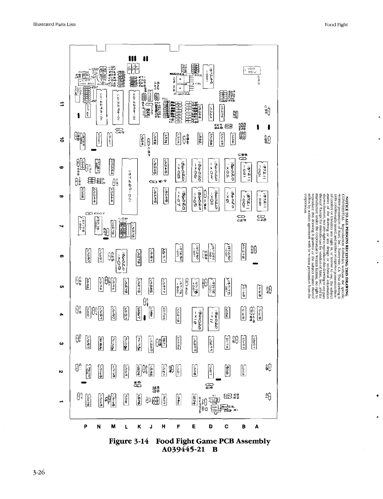
This page is a drawing, shown as the original scan.
Food Fight Ilustrated Parts Lists
Food Fight Game Printed-Circuit Board Assembly Parts List
| Designator | Description | Part No. |
Capacitors
| cl | 0.1 pF, +80%, 20%, 50 V, Ceramic Capacitor | 122002-104 | |
| c2 | 39 pF, 100 V Minimum, Dipped, Fixed-Mica Capacitor | 128002-390 | |
| C3 | 100 pF, 100 V Minimum, Dipped, Fixed-Mica Capacitor | 128002-101 | |
| C4 | 0.1 pF, +80%, -20%, 50 V, Ceramic Capacitor | 122002-104 | |
| €5-C39 | 0.1 UE, +80%, -20%, 50 V, Ceramic Capacitor | 122002-104 | |
| C40-C47 | 0.1 ME, +80%, -20%, 50 V, Ceramic Capacitor | 122002-104 | |
| C48, C49 | O.1 pF, +80%, -20%, 50 V, Ceramic Capacitor | 122002-104 | |
| C50-C52 | O.1 ME, +80%, -20%, 50 V, Ceramic Capacitor | 122002-104 | |
| C53-C55 | 0.015 uF, + 10%, 100 V, Radial-Lead Mylar Capacitor | 21-101153 | |
| C56 | 0.001 uF, + 10%, 100 V, Radial-Lead Mylar Capacitor | 21-101102 | |
| C57 | 100 pF, 35 V Aluminum Electrolytic Axial-Lead Capacitor | 24-350107 | |
| C58, C59 | O.1 uF, +80% -20%, 50 V, Ceramic Capacitor | 122002-104 | |
| CoO | 120 4B, 100 V Mica Capacitor | (Acceptable substitute is part no. 128002-151) | 128002-221 |
| C90 | 100 wE, 35 V Aluminum Electrolytic Axial-Lead Capacitor | 24-350107 |
Diodes
| CRI | ‘Type-MV5053 Light-Emitting Diode | 38-MV5053 |
| CR2 | ‘Type-IN756A, + 5%, 500 mW, 8.2 V Zener Diode | 32-1N756A |
Inductors
| Li | 100 HH, + 10% Inductor | 141002-001 |
| L2-L4 | 1 pH, + 10%, 830 mA, 0.29 Q, Peaking Coil Inductor | 141007-001 |
Integrated Circuits
| 1E | Type-74LS74 Integrated Circuit | 37-T4LS74 |
| 1F | Type-74LS86 Integrated Circuit | 37-74LS86 |
| 1H | ‘Type-7407 Integrated Circuit | 37-7407 |
| 1K | Type-74LS74 Integrated Circuit | 37-TALS74 |
| IL | ‘Type-74504 Integrated Circuit | 37-74804 |
| IM | Type-74LS1634 Integrated Circuit | 37-TALS 163A |
| IN | Type-74LS163A Integrated Circuit | 37-74LS163A |
| IP | Type-74LS175 Integrated Circuit | 37-74LS175, |
| 2B | Type-74LS02 Integrated Circuit | 37-74LS02 |
| 2C | Type-74808 Integrated Circuit | 37-74808 |
| 2D | Type-74S157 Integrated Circuit | 37-748 157 |
| 2E | Type-74L808 Integrated Circuit | 37-TALSOB |
| 2F | ‘Type-74LS21 Imegrated Circuit | 137210-001 |
| 2H | ‘Type-74L874 Integrated Circuit | 37-74LS74 |
| a | Type-74LS32 Integrated Circuit | 37-74LS32 |
| 2K | ‘Type-74L874 Integrated Circuit | 37-74LS74 |
| 2L | ‘Type-74LS163A Integrated Circuit | 37-TALS1O3A |
| 2M | Type-74LS 163A Integrated Circuit | 37-TALSIO3A |
| 2N | Type-74LS 163A Integrated Circuit | 37-7ALSIO3A |
| 2P | PROM Integrated Circuit | 136020-112 |
(Continued on next page)
Illustrated Parts Lists Food Fight
Food Fight Game Printed-Circuit Board Assembly Parts List, continued
| Designator | Description | Part No. |
| 3A | Type-74LS157 Integrated Circuit | 37-74LS157 |
| 3B | Type-74LS157 Integrated Circuit | 37-74LS157 |
| 3C | Type-74LS174 Integrated Circuit | 37-74L8174 |
| 3D | Type-74L8299 Integrated Circuit | 137180-001 |
| 3E | Type-74L8299 Integrated Circuit | 137180-001 |
| 3F | Type-74LS283 Integrated Circuit | 137204-001 |
| 3H | Type-74LS21 Integrated Circuit | 137210-001 |
| 3y | Type-74L$245 Integrated Circuit | 37-7ALS245 |
| 3P | Type-74LS157 Integrated Circuit | 37-74LS157 |
| 4A | Type-748163 Integrated Circuit | 137274-001 |
| 4B | Type-74S163 Integrated Circuit | 137274-001 |
| 4C | Type-74LS86 Integrated Circuit | 37-74LS86 |
| 4F | Type-74LS273 Integrated Circuit | 37-74LS273 |
| 4H | Type-74L5283 Integrated Circuit | 137204-001 |
| 4 | Type-74L$86 Integrated Circuit | 37-7ALSB6 |
| 4K | Type-74LS367 Integrated Circuit | 37-74LS367 |
| 4L | Type-74LS157 Integrated Circuit | 37-74LS157 |
| 4M | Type-74LS157 Integrated Circuit | 37-74LS157 |
| 4N | Type-74LS157 Integrated Circuit | 37-7ALS157 |
| 4P | Type-74800 Integrated Circuit | 37-74800 |
| SA | Type-74S 163 Integrated Circuit | 137274-001 |
| 5B | ‘Type-74S163 Integrated Circuit | 137274-001 |
| 5H | Type-74L8377 Integrated Circuit | 37-74L8377 |
| J | Type-7418245 Integrated Circuit | 37-74LS245 |
| 5K | Type-74L$273 Integrated Circuit | 37-74LS273 |
| 5L | Type-74L$273 Integrated Circuit | 37-74LS273 |
| 5M | Type-74LS194 Integrated Circuit | 37-74LS194 |
| 5N | Type-74LS194 Integrated Circuit | 37-74L$194 |
| 5P | Type-74LS32 Integrated Circuit | 37-74L832 |
| 6B | Type-74LS273 integrated Circuit | 37-74LS273 |
| 6H | Type-74LS157 Integrated Circuit | 37-74LS157 |
| o | Type-74L$157 Integrated Circuit | 37-74L8157 |
| OK | Type-74LS273 Integrated Circuit | 37-74LS273, |
| 6N | Type-74L$257 Integrated Circuit | 37-7ALS257 |
| oP | Type-74L$257 Integrated Circuit | 37-74LS257 |
| KIL | Type-74L$273 Integrated Circuit | 37-7ALS273 |
| 7M | ‘Type-74LS273 Integrated Circuit | 37-TALS273 |
| 8K/L | Microprocessor Integrated Circuit | 137289-001 |
| 8M | Type-74LS244 Integrated Circuit | 37-74LS244 |
| 8N/P | Type-74LS244 Integrated Circuit | 37-74LS244 |
| 8H | Type-74L8245 Integrated Circuit | 37-T4L8245, |
| 8H/J | Type-7418245 Integrated Circuit | 37-74L8245 |
| 8P | ‘Type-74L$02 Integrated Circuit | 37-74LS02 |
| 9H | Type-74L$245 Integrated Circuit | 7-74LS245 |
(Continued on next page)
3-28
Food Fight
Food Fight Game Printed-Circuit Board Assembly Parts List, continued Illustrated Parts Lists
| Designator | Description | Part No. | |
| oH | Type-74L8245 Integrated Circuit | 37-7ALS245 | |
| OKIL | Microprocessor Integrated | Circuit | 137289-004 |
| OM | Type-74L8244 Integrated Circuit | 37-7ALS244 | |
| oP | Type-74LS00 Integrated Circuit | 37-74LS00 | |
| 10J/K | Type-74LS14 Integrated Circuit | 37-7ALS 14 | |
| 10C | Type-7406 Integrated Circuit | 37-7406 | |
| 10E | ‘Type-74LS32 Integrated Circuit | 37-7ALS32 | |
| loc/D | Type-74LS138 Integrated Circuit | 137177-001 | |
| 10D | Type-74LS138 Integrated Circuit | 137177-001 | |
| 10H) | ‘Type-74LS32 Integrated Circuit | 37-7ALS32 | |
| 10H | Type-74L874 Integrated Circuit | 37-7ALS7A | |
| 10F | Type-74LS74 Integrated Circuit | 37-7ALS7A | |
| 10M | ‘Type-74LS161 Integrated Circuit | 37-74LS161 | |
| 10N | ‘Type-74L$161 Integrated Circuit | 37-74L8161 | |
| 10P. | Programmed Logic Array Integrated Circuit | 137313-001 | |
| 1c/D. | Type-74L8273 Integrated Circuit | 37-74LS273 | |
| 11D | Type-74L8244 Integrated Circuit | 37-TALS244 | |
| NE | Type-74L8244 Integrated Circuit | 37-74LS244 | |
| 1/125 | Quad Op-Amp Integrated Circuit | 37-LM324 | |
| 1IK/L | Custom I/O Integrated Circuit | €012294-01 | |
| 11L/M | Custom I/O Integrated Circuit | C012294-01 | |
| 11N | Custom I/O Integrated Circuit | €012294-01 | |
| 12D | D-to-A Converter Integrated Circuit | 137243-001 |
Miscellaneous
| Q2, Q3 | Nylon Snap-In Fastener | 81-4302 |
Test Point (Acceptable substitute is part no. 020670-01) 179051-002
| YI | 12.096 MHz Crystal | 144000-001 |
| SW | 8-Station Single-Throw Dual-Inline Package Bit Switch | 66-118P1T |
Erasable Programmable Read-Only Memories
| 4E | Erasable Programmable Read-Only Memory | 136020-110 |
| 4D | Erasable Programmable Read-Only Memory | 136020-111 |
| 6LM | Erasable Programmable Read-Only Memory | 136020-109 |
| 8C | Erasable Programmable Read-Only Memory | 136020-301 |
| 8D | Erasable Programmable Read-Only Memory | 136020-303, |
| 8E | Erasable Programmable Read-Only Memory | 136020-305 |
| 8F | Erasable Programmable Read-Only Memory | 136020-307 |
| 9c | Erasable Programmable Read-Only Memory | 136020-302 |
| 9D | Erasable Programmable Read-Only Memory | 136020-204 |
| 9E | Erasable Programmable Read-Only Memory | 136020-306 |
| oF | Erasable Programmable Read-Only Memory _ | 136020-308 |
Random-Access Memory
| 3K | Static RAM Integrated Circuit | 90-7036 |
| 3L | Static RAM Integrated Circuit | 90-7036 |
| 3M | Static RAM Integrated Circuit | 90-7036 |
| 3N | Static RAM Integrated Circuit | 90-7036 |
(Continued on next page)
3-29
illustrated Parts Lists Food Fight
Food Fight Game Printed-Circuit Board Assembly Parts List, continued
| Designator | Description | Part No. |
| 5C | Random-Access Memory | 137178-001 |
| 5D | Random-Access Memory | 137178-001 |
| SE | Random-Access Memory | 137178-001 |
| SF | Random-Access Memory | 137178-001 |
| 6C | Random-Access Memory | 137250-00L |
| 6D | Random-Access Memory | 137250-001 |
| GE | Random-Access Memory | 137250-00i |
| OF | Random-Access Memory | 137250-001 |
| IN | Random-Access Memory | 137178-001 |
| 7P | Random-Access Memory | 137178-001 |
| 8A | Random-Access Memory | 137211-001 |
| 8B | Randomi-Access Memory | 137211-001 |
| OA | Random-Access Memory | 137211-001 |
| OB | Random-Access Memory | 137211-001 |
| ON | Non-Volatile RAM Integrated Circuit | 137288-001 |
Resistors
| RL | 220 2, +5%, %& W Resistor | 110000-221 |
| R2, R3 | 10kQ, + 5%, 4% W Resistor | 110000-103 |
| R4 | {kQ, £5%, 4 W Resistor | 110000-102 |
| R5-R7 | 1kQ, +5%, 4 W Resistor | 110000-102 |
| R8 | 1k, +5%, %& W Resistor | 110000-102 |
| RO | 1kQ, +5%, 4 W Resistor | 110900-102 |
| R1O | 1k, £5%, %« W Resistor | 110000-102 |
| RI | 470 Q, £5%, 4 W Resistor | {10000-4711 |
| R12 | 1kQ, +5%, 4 W Resistor | 110000-102 |
| R13, R14 | 220 Q, +5%, ‘4 W Resistor | 110000-221 |
| RIS | 470 Q, +5%, 4 W Resistor | 110000-471 |
| RIG | 1kQ, +5%, 4 W Resistor | 110000-102 |
| RI7 | 470 Q, 45%, 4 W Resistor | 110000-471 |
| RIB | 220 Q, +5%, Ys W Resistor | 110000-221 |
| RIO | 1kQ, +5%, 4 W Resistor | 110000-102 |
| R20-R23 | 1kQ, +5%, 4 W Resistor | 110000-102 |
| R24-R27 | 4.7 KQ, 45%, 4 W Resistor | 110000-472 |
| R28 | 220 Q, +5%, 4 W Resistor | 110000-22 1 |
| R29 | 220 2, +5%, 4 W Resistor | 110000-22 1 |
| R30 | 1kQ, +5%, %4 W Resistor | 110000-102 |
| R31 | 470 2, +5%, ¥4 W Resistor | 110000-47 1 |
| R32 | 1kQ, +5%, % W Resistor | 110000-102 |
| R33 | 470 Q, +5%, %& W Resistor | 110000-471 |
| R34 | LkQ, + 5%, “ W Resistor | 110000-102 |
| R35 | 470 Q, + 5%, & W Resistor | 110000-47 1 |
| R36 | 1KQ, +5%, 14 W Resistor | 110060-102 |
| R37 | 470 Q, + 5%, 4 W Resistor | 110900-471 |
| R38 | ikQ, +5%, 4 W Resistor | 110000-102 |
(Continued on next page)
3-30
Food Fight Illustrated Parts Lists
Food Fight Game Printed-Circuit Board Assembly Parts List, continued
| Designator | Description | Part No. | |
| R39 | 470 Q, | 5%, va W Resistor | 110000-471 |
| R40 | 1kQ, +5%, 4 W Resistor | {10000-102 | |
| R41 | 470 Q, +5%, % W Resistor | 110000-471 | |
| R42 | 1kQ, +5%, % W Resistor | 110000-102 | |
| R43, | 470 2, +5%, % W Resistor | 110000-471 | |
| R44 | 1kQ, +5%, 4 W Resistor | 110000-102 | |
| . | R45 | 470 Q, +5%, Ye W Resistor | 110000-471 |
| R46 | 10kQ, +5%, % W Resistor | 110000-103 | |
| R47-R49 | 100 kQ, +5%, 4 W Resistor | 110000-104 | |
| R50-R57 | 4.7kQ, +5%, 4 W Resistor | 110000-472 | |
| R58 | 10kQ, +5%, %4 W Resistor | 110000-103. | |
| R59-62 | 1kQ, +5%, 4 W Resistor | 110000-102 | |
| R63-RG67 | 10 kQ, +5%, 4 W Resistor | 110000-103 | |
| ROB | 22 kQ, +5%, % W Resistor | 110000-223 | |
| R69-R71 | 330 kQ, +5%, V4 W Resistor | 110000-334 | |
| R72-R74 | 910 Q, +5%, %& W Resistor | 110000-911 | |
| R75 | 220 Q, +5%, % W Resistor | 110000-221 | |
| R76 | 1kQ, +5%, % W Resistor | 110000-102 | |
| R77 | 220 Q, +5%, ‘4 W Resistor | 110000-221 | |
| R78. | 4.7kQ, +5%, % W Resistor | 110000-472 | |
| R79 | 330 Q, £5%, 4 W Resistor | 110000-331 | |
| R9G, R91 | 4.7 kQ, +5%, 4 W Resistor | 110000-472 | |
| R207 | 1kQ, +5%, % W Resistor | 110000-102 |
,
Sockets
| 4D | 28-Contact Medium-Insertion-Force Integrated Circuit Socket | 79-42C28 | |
| 4E | 28-Contact Medium-Insertion-Force Integrated Circuit Socket | 79-4228 | |
| 5c | 22-Contact Medium-Insertion-Force Integrated Circuit Socket | 79-42C22 | |
| 5D | 22-Contact Medium-Insertion-Force Integrated Circuit Socket | 79-42C22 | |
| 5E | 22-Contact Medium-Insertion-Force Integrated Circuit Socket | 79-42C22 | |
| SF | 22-Contact Medium-Insertion-Force Integrated Circuit Socket | 79-42C22 | |
| 6C | 22-Contact Medium-Insertion-Force Integrated Circuit Socket | 79-42C22 | |
| 6D | 22-Contact Medium-Insertion-Force Integrated Circuit Socket | 79-42C22 | |
| 6E | 22-Contact Medium-Insertion-Force Integrated Circuit Socket | 79-42C22 | |
| OF | 22-Contact Medium-Insertion-Force Integrated Circuit Socket | 79-42C22 | |
| 6L/M | 28-Contact Medium-Insertion-Force Integrated Circuit Socket | 79-42C28 | |
| JN | 22-Contact Medium-Insertion-Force Integrated Circuit Socket | 79-42C22 | |
| 7P | 22-Contact Medium-Insertion-Force Integrated Circuit Socket | 79-42C22 | |
| BA | 24-Contact Medium-Insertion-Force Integrated Circuit Socket | 79-42C24 | |
| 8B | 24-Contact Medium-Insertion-Force Integrated Circuit Socket | 79-42C24 | |
| . | 8C | 28-Contact Medium-Insertion-Force Integrated Circuit Socket | 79-42C28 |
| 8D | 28-Contact Medium-Insertion-Force Integrated Circuit Socket | 79-42C28 | |
| 8E | 28-Contact Medium-Insertion-Force Integrated Circuit Socket | 79-42C28 | |
| - | 8F | 28-Contact Medium-Insertion-Force Integrated Circuit Socket | 79-42C28 |
| 8K/L | 64-Contact Medium-Insertion-Force Integrated Circuit Socket | 79-42C64 |
(Continued on next page)
3-31
Mlustrated Parts Lists Food Fight
Food Fight Game Printed-Circuit Board Assembly
Parts List, continued
| Designator | Description | Part No. |
| 9A | 24-Contact Medium-Insertion-Force Integrated Circuit Socket | 79-42C24 |
| OB | 24-Contact Medium-Insertion-Force Integrated Circuit Socket | 79-42C24 |
| 9C | 28-Contact Medium-Insertion-Force Integrated Circuit Socket | 79-42C28 |
| 9D | 28-Contact Medium-Insertion-Force Integrated Circuit Socket | 79-42C28 |
| 9E | 28-Contact Medium-Insertion-Force Integrated Circuit Socket | 79-42C28 |
| oF | 28-Contact Medium-Insertion-Force Integrated Circuit Socket | 79-42C28 |
| OKIL | 64-Contact Medium-Insertion-Force Integrated Circuit Socket | 79-42. C64 |
| 10P | 20-Contact Medium-insertion-Force Integrated Circuit Socket | 79-42C20 |
| L1K/L | 40-Contact Medium-Insertion-Force Integrated Circuit Socket | 79-42C40 |
| 11L/M | 40-Contact Medium-Insertion-Force Integrated Circuit Socket | 79-42C40 |
| 11N | 40-Contact Medium-Insertion-Force Integrated Circuit Socket | 79-42C40 |
| 12D | 28-Contact Medium-insertion-Force Integrated Circuit Socket | 79-42C28 |
Transistors
| Ql | Type-2N3904, 350 mW, 60 V NPN Transistor | 34-2N3904 |
| Q2, Q3 | Type-2N6044, 8 A, 80 V NPN Transistor | 34-2N6044 |
| Q4 | ‘Type-2N3904, 350 mW, 60 V NPN Transistor | 34-2N3904 |
Food Fight Illustrated Parts Lists
NOTICE TO ALL PERSONS RECEIVING THIS DRAWING CONFIDENTIAL: Reproduction Torbidden without the spc written permission of Atari, Inc., Sunnyvale, CA. This drawi R33 ‘only conditionally issued, and neither receipt nor possession {eK} theret confers or transfers any right wn, or license to use. the su o
| ject matter ofthe drawing or any desig ortechnicl information | +. | » |
shown thereon, nor any right to reproduce this drawing or any 9 oo FRB 1
| pat thereot. Encept for manufacture by vendors Of Ath, Mes | ce, | caate | Q |
fd for manufacture under the corporation's writen lens, n0 g ch
| aac) reprodce hs drawing it ante ur the subctm | : | con | tale | it} |
| thereof unless by writen agreement with Or wetten emision | as | 2 | = |
from the corporation een)
| c20. | C2) | 0 |
C19
| —=+ | 3300, | -— |
35V
C18 ae +/— 5V 0
pS2 Ct 5.6K
a
- 3s R241, 7Wh— oO &
| TiP32 | TOAZ002 A | TDA2002A |
| M=Q2_ | inacoz QS | Q7 |
| apa | C7 a | 8 cecooa’S |
SIRS 1 lg CCG) 49) CISD cen {= e airs [OS | PEE cg 13 220] R21, i/2w
Figure 3-15 Regulator/Audio II PCB Assembly A035435-04 K
3-33
Iustrated Parts Lists Food Fight
Regulator/Audio II PCB Assembly Parts List
| Designator | Description | Part No. |
Capacitors
| cl | 470 pF, 25 V, Aluminum Electrolytic Fixed Axial-Lead Capacitor | 24-250477 |
| C2 | 0.001 pF, 50 VY, Ceramic-Disc Axial-Lead Capacitor | 122002-102 |
| C3 | 0.1 wF, 50 V, Ceramic-Disc Axial-Lead Capacitor | 122002-104 |
| C4 | 470 uF, 25 V, Aluminum Electrolytic Fixed Axial-Lead Capacitor | 24-250477, |
| cs | 0.01 pF, 25 V Minimum, Ceramic-Disc Axial-Lead Capacitor (Acceptabie | 106015-103 |
substitute is part no. 122005-103)
| co | 0.22 uF, 25 V, Ceramic-Disc Axial-Lead Capacitor | 122004-224 |
| C7 | 0.001 wE, 50 V, Ceramic-Disc Axial-Lead Capacitor | 122002-102 |
| ce | 0.22 uF, 25 V, Ceramic-Disc Axial-Lead Capacitor | 122004-224 |
| C9, C10 | 3300 pF, 35 V, Aluminum Electrolytic Fixed Axial-Lead Capacitor | 24-350338 |
| cll | 0.1 uF, 50 V, Ceramic-Disc Axial-Lead Capacitor | 122002-104 |
| cl2 | 470 pF, 25 V, Aluminum Electrolytic Fixed Axial-Lead Capacitor | 24-250477 |
| cl3 | 1000 uF, 25 Vv, Aluminum Electrolytic Fixed Axial-Lead Capacitor | 24-250108 |
| cl4 | 0.01 BE, 25 V Minimum, Ceramic-Disc Axial-Lead Capacitor | 100015-103 |
(Acceptable substitute is part no, 122005-103)
| cis | 0.22 uF, 25 V, Ceramic-Disc Axial-Lead Capacitor | 122004-224 |
| C16 | 0.001 4, 50 V, Ceramic-Dise Axial-Lead Capacitor | 122002-102 |
| C17 | 0.22 wF, 25 V, Ceramic-Disc Axial-Lead Capacitor | 122004-224 |
| C18, C19 | 3300 wE, 35 V, Aluminum Electrolytic Fixed Axial-Lead Capacitor | 24350338 |
| €20, C2 | 0.1 uF, 50 V, Ceramic-Disc Axial-Lead Capacitor | 122002-104 |
Diodes
| CRI, C4 | Type-IN4002, 1 A, LOO V Silicon Rectifier Diode | 31-1N4002 |
| CR5-CR8 | Type-1N5401, 3 A, 100 V Silicon Rectifier Diode | 31-1N5401 |
Integrated Circuits
| fon | Type-LM305, 5 V, Linear Voltage Regulator | 37-LM305 |
| Qs | ‘Type-TDA2002A, 8 W, Linear Audio Amplifier Integrated Circuit | 137151-002 |
| Q7 | ‘Type-TDA2002A, 8 W, Linear Audio Amplifier Integrated Circuit | 137151-002 |
Resistors
| RI | 270 2, +5%, V4 W Resistor | 110000-271 |
| R3 | 33 Q, 45%, 4 W Resistor | 110000-330 |
| R4 | 100 &, 45%, 4 W Resistor | 110000-101 |
| RS | 2.7 Q, +5%, 1 W Resistor | 110009-027 |
| RO | 3.9 kQ, +5%, % W Resistor | 110000-392 |
| R7 | 7.5 kQ, +5%, 4 W Resistor | 110000-752 |
| R8 | 1 kQ Horizontal PCB-Mounting Cermet Potentiometer (Acceptable | 119002-102 |
substitute is part no. 19-315102)
| RO | 220 Q, +5%, ¥% W Resistor | 110001-221 |
| RIO | 1Q, £5%, % W Resistor | 116000-010 |
| Ril | 10 &, +5%, 4 W Resistor | 110000-190, |
| RI2Z | 100 2, +5%, 4 W Resistor | 110000-101 |
| R13, R14 | 10 kQ, +5%, % W Resistor | 110000-103 |
(Continued on next page)
Food Fight Illustrated Parts Lisis
Regulator/Audio II PCB Assembly Parts List, continued
| Designator | Description | Part No. |
| RID | 1Q, +5%, 4 W Resistor | 110000-010 |
| R20 | 10 2, +5%, 4 W Resistor | 110000-100 |
| R21 | 220 Q, +5%, % W Resistor | 310001-221 |
| R22 | 100 Q. +5%, 4 W Resistor | 110000-101 |
| R24 | 0.1. Q, +3%, 7 W Wirewound Resistor | 19-100P 1015 |
| R27, R28 | 1kQ, £5%, & W Resistor | 110000-102 |
| R29, R30 | 102, +5%, 4 W Resistor | 110000-100 |
| R32, R33 | 5.6 kQ, +5%, % W Resistor | 110000-562 |
Transistors
| Q2 | Type-TIP32 PNP Power Transistor | 33-TIP32 |
| 3 | Type-2N3055 NPN Silicon. Transistor | 34-2N3055, |
Mechanical Parts
| J6 | 6-Position Connector Receptacle | 79-58306 |
| V | 9-Position Connector Receptacle | 79-58308 |
| 38 | 4-Position Connector Receptacle | 79-58354 |
| Jo | 6-Position Connector Receptacle | 79-58306 |
| J10 | 12-Position Connector Receptacle | 79-58346 |
| Q2 | #6-32 x %-Inch Binder-Head Nylon Screw | 75-F60405 |
| Q3 | #6-32 Nut/Washer Assembly | 75-99516 |
| 3 | ‘Thermally Conductive Silicon Insulator | 78-16008 |
| Q5 | Thermally Conductive Silicon Insulator | 78-16008 |
| Q5, Q7 | #6 x ¥Inch Cross-Recessed Pan-Head Thread-Forming Type-AB Zinc- | 72-66068 |
Plated-Steel Screw
Heat Sink 934531-01 Test Point (Acceptable substitute is part no. 020670-01) 179051-001
Food Fight Mlustrated Parts Lists
A035888-01 (Transtormer assy.)
A021084-xx (Voltage plugs)
29-053 (Capacitor) 03454401 (Fuse block cover)
79-441101 (Fuse post)
78-70501SC ; (Capacitor bracket) ee 46-2014002 * or 46-2017002 (Fuse) x
A035891-02 034482.02 (Fuse harness assy.) va (Chassis)
46-301203 (Fuse)
037639-xx. (Label)
(Bushing)
A034630-01 79-3206 (Filter Assy.) (Fuse block) 037640-01 46-2014002 (Label) (Fuses)
79-15021001 ‘A035890-01 (Terminal block) (Power harness)
A034629-01 3A-MDA3501 © (AC harness) (Rectitier)
Figure 3-16 Color Raster-Scan Power Supply Assembly A037671-01 & -03 H
Food Fight
Power Supply Assembly Parts List US-Built Game A037671-01 G Illustrated Parts Lists
| Designator | Description | Part No. |
| cl | 27,000 uF, 15 VDC Electrolytic Capacitor | 29-053 |
| Cl | 2-Inch Diameter Capacitor Mounting Bracket | 78-70501SC |
| cRI | ‘Type-MDA 3501 Bridge Rectifier | 3A-MDA3501 |
| Fl | Panel-Mounting Non-Indicating 3AG Cartridge-Type Fuse Post | 79-441101 |
| FI | 7 A, 250 V, 3AG Slow-Blow Glass Cartridge-Type Fuse | 46-2017002 |
| Fl | Label for Fuse Value | 037639-01 |
| F2 | 4 A, 250 V, 3AG Slow-Blow Glass Cartridge-Type Fuse | 46-2014002 |
| F2-F6 | 5-Position 3AG Fuse Block with 4-Inch Quick-Disconnect Terminals | 79-3206 |
| F2-F6 | Fuse Harness Assembly | A035891-02 |
| F2-F6 | Fuse Block Cover | 034544-01 |
| F2-F6 | Label for Fuse Values | 037640-01 |
| F3 | 20 A, 32 V, 3AG Slow-Blow Glass Cartridge-Type Fuse | 46-301203 |
| F4 | 2-Circuit Single-Row Terminal Block (located under F4) | 79-15021001 |
| F4-F6 | 4 A, 250 V, 3AG Slow-Blow Glass Cartridge-Type Fuse | 46-2014002 |
| FLI | RFI Filter Assembly (designation not marked) | A034630-01 |
| j2 | Power Harness Assembly | A035890-01 |
| 3 | Voltage Plug for 120 V (105-135 VAC) (yellow wire color—plugs into J3) | A02 1084-02 |
| J4A | AC Harness Assembly | A034629-01 |
| TI | ‘Transformer Assembly (designation covered—Acceptabie substitute is part no, | A035888-01 |
A035888-02) Nylon Type 6/6 Hole Bushing with %Inch Inside Diameter x °%,-Inch 78-2708 Outside Diameter x 4-Inch Thick
Power Supply Chassis Base 034482-02 Metal Base Plate (not shown in illustration) 037243-01
3-37
Illustrated Parts Lists
Power Supply Assembly Parts List Ireland-Built Game A037671-03 G Food Fight
| Designator | Description | Part No. |
| CL | 27,000 wF, 15 VDE Electrolytic Capacitor | 29-053 |
| cL | 2-Inch Diameter Capacitor Mounting Bracket | 78-70501SC |
| CRI | Type-MDA 3501 Bridge Rectifier | 3A-MDA3501 |
| FI | Panel-Mounting Non-Indicating 3AG Cartridge-Type Fuse Post | 79-441101 |
| FI | Label for Fuse Value | 037639-02 |
| FI, F2 | 4 A, 250 V, 3AG Slow-Blow Glass Cartridge-Type Fuse | 46-2014002 |
| F2-F6 | 5-Position 3AG Fuse Block with 4-Inch Quick-Disconnect Terminals | 79-3206 |
| F2~F6 | Fuse Harness Assembly | A03589 1-02 |
| F2-F6 | Fuse Block Cover | 034544-01 |
| F2-F6O. | Label for Fuse Values | 037640-01 |
| F3 | 20 A, 32 V, 3AG Slow-Blow Glass Cartridge-Type Fuse | 46-301203 |
| F4 | 2-Circuit Single-Row Terminal Block (located under F4) | 79-1502 1001 |
| F4-FO | 4A, 250 V, 3AG Slow-Blow Glass Cartridge-Type Fuse | 46-2014002 |
| FLI | RFI Filter Assembly (designation not marked) | A034630-01 |
| Jj2 | Power Harness Assembly | A035890-01 |
| B | Voltage Plug for 220 V (200-240 VAC) (blue wire color—phugs into J3) | A021084-04 |
| B | Voltage Plug for 240 V (220-260 VAC) (brown wire color—plugs into J3) | A02. 1084-05 |
| J4A | AC Harness Assembly | A034629-01 |
| TL | Transformer Assembly (designation covered—Acceptable substitute is part no | A035888.01 |
‘A035888-02) Nylon Type 6/6 Hole Bushing with %-Inch Inside Diameter x *%4-Inch 78-2708 Outside Diameter x 4 -Inch Thick
Power Supply Chassis Base Metal Base Plate (not shown) 034482-02 037243-01
3-38
Gimbal Joystick Maintenance and Repair
Normal maintenance involves lubricating four parts in the joystick control approximately every three months (this requires removing the control). First, open the control panel. Tilt the control panel towards you. Then unsolder the harness from the two potentiometers on the joystick assembly. From the inside of the control panel, remove the four flat washers, hex nuts, and carriage bolts that mount the joystick to the control panel. Then open up the joystick control assembly by removing the four flat washers, hex nuts, and long screws (see Figure 3-4), At this point, most of the parts should disassemble. For lubrication, use only Nyogel 779 lubricant (Atari part no. 178027-001). Lubricate the following parts inside the control: © — The insides of the two black linkages, located on the potentiometer shafts.
- The insides of the two gimbals, where the bottom of the shaft wears against them, ° The sides of the pivot ball housings at the four holes where the gimbals are attached. If the bellows need replacing, remove both gimbals and the bellows cap. Slide the bellows off the bottom of the shaft. Slide the new bellows up over shaft. Reassemble the joystick control, and then reinstall it in the control panel. Reconnect the harness wires as shown in Figure 3-3. Make sure the right colors go to the tabs on the potentiometers. Refer to Chapter 2, Self-Test Menu, for instructions on how to recalibrate the joystick.
Appendix A
If the square pattern control plate (part no. 036953-01) or mounting plate (part no. 036954-0i) need replacing, disassemble the lower half of the control by removing the four hex nuts, Support the pivot ball of the pivot shaft assembly on a hard surface that has a hole slightly deeper than the length of the roll pin (see Figure A-1), Knock out the #.-inch roll pin using a #.-inch punch, Reassemble in reverse order.
Y~e-inch punch Pivot ball Le
Roll pin
Figure A-1 Disassembling
the Pivot Shaft Assembly
This page carries no recoverable text. It is a drawing or a photograph. See the original scan.
«7
YOUR COMMENTS, PLEASE!
Your comments will assist Atari in improving our publications. The comments are an important part of preparing for revisions of game manuals. Please write in the space below. No postage stamp is necessary if mailed in the U.S.A.
If you have any technical questions about certain ATARI games products, or are requesting additional publications, we will immediately forward your note to the appropriate person.
Page: Comments:
Fill in if you wish a reply:
Name
Firm O Distributor
Address 0 Operator
City State Zip C Other
Area Code Phone Food Fight™ 2nd printing
First Fold
No postage necessary if mailed in the United States
BUSINESS REPLY MAIL
FIRST CLASS PERMIT NO. 1004 SUNNYVALE, CA
POSTAGE WILL BE PAID BY ADDRESSEE
Attn.: Field Service/Coin-Op Division P.O. Box 427 Sunnyvale, California 94086 Lh Le [|
Atari, Inc. be | Le be Le De
Second Fold
wos
a8po sp adv,
Food Fight™ 2nd printing
YOUR COMMENTS, PLEASE!
Your comments will assist Atari in improving our publications. The comments are an important part of preparing for revisions of game manuals. Please write in the space below.
If you have any technical questions about certain ATARI games products, or are . requesting additional publications, we will immediately forward your note to the appropriate person.
Page: Comments:
Fill in if you wish a reply: e Name
. Firm C1 Distributor
Address ( Operator
City Country 0 Other
Phone: Country Code Local Number
First Fold
Atari Ireland Limited Attn.: Field Service/Coin-Op Division
Tipperary Town, Ireland
Second Fold
28po spp ade, Attach Necessary Postage
WOT
This page carries no recoverable text. It is a drawing or a photograph. See the original scan.
This page carries no recoverable text. It is a drawing or a photograph. See the original scan.
PEG LWE, SRR GE GE YE EE SS SE ES
Warranty
Seller warrants that its printed-circuit boards and parts thereon are free from defects in material and workmanship under normal use and service for a period of ninety (90) days from date of shipment. Seller warrants that its video displays (in games supplied with displays) are free from defects in material and workmanship under normal use and service for a period of thirty (30) days from date of shipment. None of the Seller's other products or parts thereof are warranted. If the products described in this manual fail to conform to this warranty, Seller’s sole liability shall be, at its option, to repair, replace, or credit Buyer’s account for such products which are returned to Seller during said warranty period, provided: {a) Seller is promptly notified in writing upon discovery by Buyer that said products are defective; (b)Such products are returned prepaid to Seller’s plant; and (c)Selier’s examination of said products discloses to Seller’s satisfaction that such alleged defects existed and were not caused by accident, misuse, neglect, alteration, improper repair, installation, or improper testing. In no event shall Seller be liable for loss of profits, loss of use, incidental or consequential damages. Except for any express warranty set forth in a written contract between Seller and Buyer which contract supersedes the terms herein, this warranty is expressed in lieu of all other warranties expressed or implied, including the implied warranties of merchantability and fitness for a particular purpose, and of all other obligations or liabilities on the Seller’s part, and it neither assumes nor authorizes any other person to assume for the Seller any other liabilities in connection with the sale of products by Seller.
The use of any non-Atari parts may void your warranty, according to the terms of the warranty. The use of any non-Atari parts may also adversely affect the safety of your game and cause injury to you and others. Be very cautious in using non-Atari-supplied components with our games, in order to insure your safety. Atari distributors are independent, being privately owned and operated. In their judgment they may sell parts or accessories other than Atari parts or accessories. Atari cannot be responsible for the quality, suitability or safety of any non-Atari part or any modification including labor which is performed by such distributor.
A
ATARI
ATARI, INC. 790 SYCAMORE DRIVE P.O, BOX 906 MILPITAS, CALIFORNIA 95035 408/942-3100 ¢ TELEX 35-7488