Pac-Man Parts and Operating Manual (Dec 1980)
Puck Man (Japan, set 1) (Namco, 1980) · Parts & Operating Manual · 63 pages · 65 sections · original scan
GAME NOS. 932, 933 & 934
MIDWAY’S
DECEMBER, 1980
PARTS AND
OPERATING MANUAL
COCKTAIL #933
UP-RIGHT #932 MINI #934
MIDWAY MFG. CO. A BALLY COMPANY
MIDWAY MFG. CO 10750 WEST GRAND AVENUE
~ FRANKLIN PARK, ILLINOIS 60131 U.S.A.
PHONE: (312) 451-1360 CABLE ADDRESS: MIDCO TELEX NO.: 72-1596 FORM NO. 0932-00300—0000
TABLE OF CONTENTS
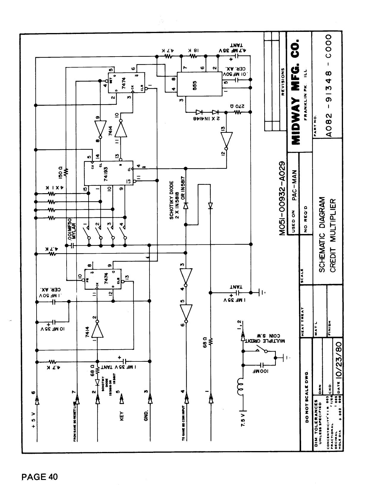
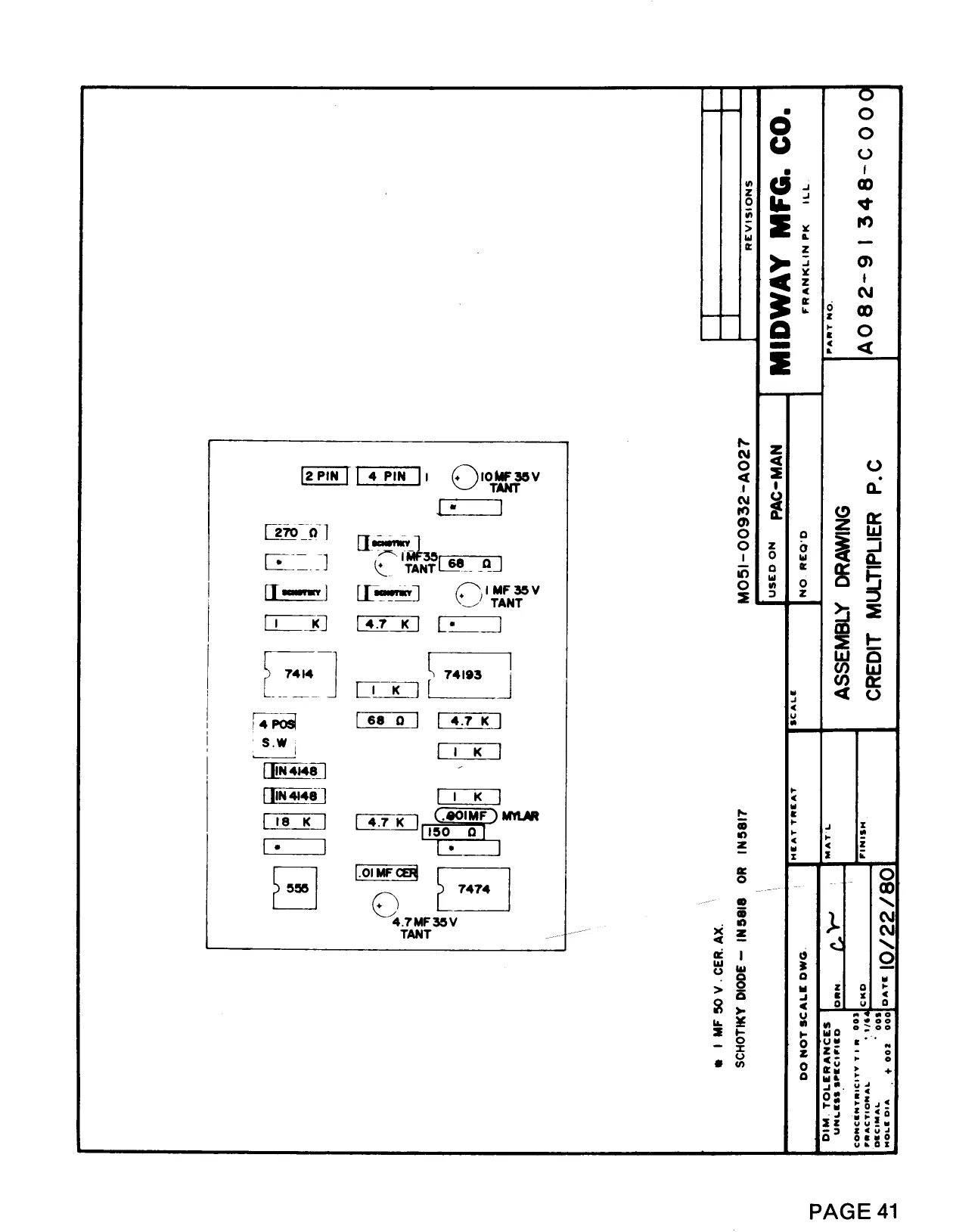
Page No. GENERAL INSTRUCTIONS - UP-RIGHT & MINI 1 GENERAL INSTRUCTIONS - COCKTAIL 2-3 MONITOR ADJUSTMENTS - ELECTROHOME 4—6 MONITOR ADJUSTMENTS - WELLS-GARDNER 7—8 SWITCH ADJUSTMENTS 9 NO. 0932 - PAC-MAN UP-RIGHT - PHOTOGRAPH 10—11 INTERIOR ACCESS PICTURE - UP-RIGHT 12—13 NO. 0934 - PAC-MAN MINI - PHOTOGRAPH 14-15 INTERIOR ACCESS PICTURE - MINI 16—17 CONTROL ASSEMBLY - ALL GAME VERSIONS 18—19 PUSH BUTTON ASSEMBLY - UP-RIGHT & MINI 20—21 DOUBLE ENTRY COIN DOOR ASSEMBLY 22—23 NO. 0933 - PAC-MAN COCKTAIL - PHOTOGRAPH 24—26 COCKTAIL ADDITIONAL PARTS LIST 27 SINGLE ENTRY COIN DOOR ASSEMBLY 28—29 TRANSFORMER BOARD ASSEMBLY 30—31 GAME BOARD SCHEMATIC 32 GAME BOARD COMPONENT LAYOUT “‘A”’ VERSION 33 GAME BOARD COMPONENT LAYOUT ‘‘B”’ VERSION 34 GAME LOGIC CHIP NUMBER & FUNCTION 35 Z-80 SYNC BUSS CONTROLLER SCHEMATIC 36 Z-80 SYNC BUSS CONTROLLER COMPONENT LAYOUT 37 V-RAM ADDRESSER SCHEMATIC 38 V-RAM ADDRESSER COMPONENT LAYOUT 39 CREDIT MULTIPLIER SCHEMATIC 40 CREDIT MULTIPLIER COMPONENT LAYOUT a WIRING DIAGRAM - UP-RIGHT ‘‘A’”’ VERSION 42 WIRING DIAGRAM - UP-RIGHT ‘‘B’”’ VERSION 43 WIRING DIAGRAM - MINI ‘“‘A’’ VERSION 44 WIRING DIAGRAM - MINI ‘‘B’’ VERSION 45 WIRING DIAGRAM - COCKTAIL 46 19’? MONITOR SCHEMATIC - WELLS-GARDNER 47 REPLACEMENT PARTS LIST 48—49 19’? MONITOR SCHEMATIC - ELECTROHOME 50 REPLACEMENT PARTS LIST 51—54 13’? MONITOR SCHEMATIC - ELECTROHOME 55 REPLACEMENT PARTS LIST 56—59 MODIFICATION OF PAC-MAN GAME P.C.B. 60
COPYRIGHT 1980 ©BYMIDWAYMFG.CO. ALL RIGHTS RESERVED. NO PART OF THIS PUBLICATION MAY BE REPRODUCED BY ANY MECHANICAL, PHOTOGRAPHIC, OR ELECTRONIC PROCESS, OR IN THE FORM. OF A PHONOGRAPHIC RECORDING, NOR MAY IT BE TRANSMITTED, OR OTHERWISE COPIED FOR PUBLIC OR PRIVATE USE, WITHOUT PERMISSION FROM THE PUBLISHER.
FOR PERMISSION REQUESTS, WRITE: MIDWAY MFG. CO., 10750 W. GRAND AVE., FRANKLIN PARK, IL 60131
GENERAL INSTRUCTIONS FOR ‘‘PAC-MAN”’ UPRIGHT AND MINI
INSTALLATION
- Remove shipping cleats located on bottom of cabinet.
- Install four (4) provided leg levelers to bottom of cabinet and level cabinet.
- The power is controlled by a switch located on top of the cabinet. Additional taps have been provided on the transformer to compensate for fluctuating line voltage. LINE VOLTAGE SAFETY SWITCH A line voltage safety switch has been provided for your protection. It is located on the right rear side of the cabinet in the back door area. When the back door is removed, it opens the circuit to the line voltage. To restore power (when servicing), pull switch fully out. VOLUME CONTROL The volume control pot is located on the Game Logic Board (P.C. A082-91352-A000). This pot controls the volume of all sounds and may be varied as desired by rotating pot control. ADJUSTMENT SWITCHES Located on Game Logic Board (P.C. A082-91352-A000) and may be adjusted as indicated on separate instruction card in back box area.
GAME LOGIC P.C. AO82-91352—A 000
ADJ. SW.
VOLUME CONTROL:
TO REMOVE CONTROL PANEL AND MONITOR DISPLAY GLASS . Open coin door. . Release two (2) clamps located below Control Panel on each side of cabinet. . Disconnect control panel jack. . Remove control panel. . Remove monitor display glass. CREDIT PUSH BUTTON SWITCH Located in cash box area and is readily accessible by opening coin door. This switch is provided as a test aid and awards one credit without advancing coin meter. OQRwons
M051-00932-A003
GENERAL INSTRUCTIONS FOR ‘‘PAC-MAN”’ COCKTAIL TABLE
INSTALLATION
- Remove shipping cleats located on bottom of cabinet.
- Install four (4) provided leg levelers on bottom of cabinet and level cabinet.
- The power is controlled by a switch located on the bottom of the cabinet. Additional taps have been provided on the transformer to compensate for fluctuating line voltage.
LINE VOLTAGE SAFETY SWITCH A line voltage safety switch has been provided for your protection. It is located in the cabinet on the left side of the coin door. When the coin door is opened the circuit to the line voltage is interrupted. To restore power (when servicing), pull switch fully out.
VOLUME CONTROL The volume control pot is located on the Game Logic Board (P.C. A082-91352-A/B000). The pot controls the volume of all sounds and may be varied as desired by rotating pot control.
ADJUSTMENT SWITCHES Located on Game Logic Board (P.C. A082-91352-A/B000) and may be adjusted as indicated on separate instruction card in back door area.
GAME LOGIC P.C. AO82-91352-A/B000
ADJ. SW.
VOLUME CONTROL 8)
CREDIT PUSH BUTTON SWITCH
Located to right of cash box and is readily accessible by opening coin door. This switch is provided as a test aid and awards one credit without advancing coin meter.
TEST SLIDE Located to right of cash box and is readily accessible by opening coin door. When placed in ‘‘ON’”’ position, this switch indicates test mode.
M051-00933-A003
GAME BOARD TEST Place test slide switch in ‘‘ON’’ position. If game board is good, the following information will be displayed on the screen: OK Coin Adjustment Setting Bonus Adjustment Setting Number of PAC-MAN Per Game Setting
Game Version
RAM/ROM TEST If any of the Rams or Roms are faulty, the following information will be displayed on the screen:
BAD ROM LOCATION CODE BAD RAM LOCATION CODE
Display Location Display Location
| M-Rom-0 | 6E | Bad V Ram-0 | 4k |
| M-Rom-1 | 6F | Bad V Ram-1 | 4N |
| M-Rom-2 | 6H | Bad C Ram-0 | 4L |
| M-Rom-3 | 6J | Bad C Ram-1 | 4P |
Bad W Ram-0 4M Bad W Ram-1 4R
CONTROL PANEL AND COIN SWITCH TEST
To verify operation of any switch, close switch in question. If switch is operating properly, agame sound will emit when closure is made.
TO SERVICE MONITOR, GAME BOARD AND TRANSFORMER ASSY.
- Open coin box door and release two (2) clamps indicated on sketch below.
- Grasp monitor mounting panel at ‘‘A’’ and open as indicated in sketch below.
OND
MONITOR - GENERAL INSTRUCTIONS
Service Set-Up Procedure
1.7 Spread the tabs apart as little as necessary and rotate both rings together to center the red band horizontally on the face of the CRT (approximate). (See Fig. 5) 1.8 Slide the yoke towards the bel! of the picture tube slowly to obtain a uniform red field (pure in color) across the entire tube face. Juggle back and forth slightly as necessary. Lightly tighten yoke retaining clamp. 1.9 Momentarily switch on a cross-hatch signal and rotate yoke to level the pattern on the face of CRT. 1.10 Return generator to regain red raster. 1.11. Turn off red field and check for pure field for each of the green and blue fields. Reposition yoke if necessary to obtain optimum purity on all fields. 1.12 Tighten yoke retaining clamp to prevent yoke shift or rotation. (Do not install wedges at this time.) CRT SOCKET P.C.B.
sercen ve fa)
oe) OH | eve coroee vn concen onwe | | oncen curore ve no onve | fT Th} no cuore va
BE CAREFUL OF “A” AND “B’ BOOST VOLTAGES PRESENT ON P.C.B. Figure 3
(REAR VIEW)
Long and short protrusions
Let the protrusions come in line.
ZEA. Centre Bring the green bend to the centre. Figure 5
2.2
2.6
3.0
3.2
3.3
3.4
3.5 Static and Dynamic Convergence
Turn on green input to obtain magenta (red/blue) and green crosshatch lines. Rotate the 6-pole (rear) pair of magnets as a unit to minimize separation of the magenta and green lines (figure 7). Vary angle between the two tabs and further rotate as a unit to finalize.
When converence of 3 colors is optimized (static in center and dynamic around edges) apply stripe of paint or nail polish to converence magnet rings to prevent movement. If applicable, tighten locking ring carefully. Remove temporary wedge from yoke. Tilt yoke in updown and left-right direction for best circumference convergence and install 3 wedges. (it is best to use 3 new wedges since they have adhesive backing. Simply pull off tape, slide wedge in place and press outer flap down firmly. For more permanency apply small quantity of silastic or similar material at junction of wedges and picture tube. Do not disturb while material is setting. (Order wedges by part number 39-1233-01).
White Balance (Grey Scale Tracking) Refer to figure 3. Do the following in subdued light:
Let the red and biue lines come in line by
turning two 4-pole magnets
en te Sipe es Figure 6
{FRONT VIEW)
contre
Let the green and magents lines come in line by turning two 6:pole magnets. ; Figure 7
(REAR VIEW!
Roughly adjust the circumferential con: vergence and install one wedge temporarily. Figure 8
(FRONT VIEW)
Tilting the yoke upward will move the lines, .
a8 shown with the arrows” Figure 9
Tilting the yoke 10 the right will move the lines as shown with the arrows,
3.6 Adjust the red and green drive controls for “neutral white” on high white picture areas. Generally these controls will be left at mech. centre. 3.7. Note: When monitor is re-connected with the game the screen control (G2) may require a_ slight adjustment to obtain proper black level. (the black portion of picture just extinguished).
[REAR VIEW]
Figure 11
4.0 Power Supply The regulated +B1 control (R909) has been factory adjusted and normally requires no adjustment. However, if any repairs have been made to the chassis it is recommended that this adjustment should be made.
- Allow 5 minutes to warm up.
- No signal applied.
- Connect an accurate D.C. voltmeter to TP-91 or the emitter of X04 power regulator transistor.
- Adjust R909 for 120V. (See fig. 1)
5.0 Focus Adjust focus control for best overall definition and picture detail an average signal applied. (Highlights should be favoured.)
6.0 Electrohome has developed a color service generator that is specifically designed for use with the G07 color data monitor. It provides the monitor with both horizontal and vertical sync, as well as the following test patterns: Color Service Generator for G07 Monitor
- Fine cross-hatch pattern
- Broad bar cross-hatch pattern
- Complete field Three color selection switches, red, green and blue, provide the ability to display the above patterns in the three primary colors as well as the three secondary colors. This product may be ordered from:
Contracts Marketing
ELECTROHOME Electronics 809 Wellington St. North
Kitchener, Ontario
Canada N2G 4J6 Telephone: (519) 744-7111, Ext. 567 7.0
7A
7.2
7.3
8.0
8.1
8.2
X-Ray Emission Check
Assure the power supply B1 is properly adjusted to 120V DC. See Item 4.0 (page 8) Assure that the anode voltage does not exceed max. as per Item 2.0 page 4.
Assure that the high voltage hold down circuit is operating correctly. Use the following procedure.
- Increase the B1 greater than 138.5V by shorting collector/emitter of the power regulator, X04.
- Observe that the anode voltage (EHT) goes to 0. If the EHT does not go to 0, a fault must be located and repaired.
- Remove short and set should return to normal operation. (Note, after the short is removed some monitors may not restart. In this case, remove power from monitor momentarily and normal operation will be restored.
The protector circuit consists of the components
shown below in Fig. 13 with a circuit description.
BL
X 701 2SC454C Ta.103 $39 Kohm p 701 +,-1% — RD20EV2 eT R 704 7.68 Kohm +k f| C701 R701 100/16 4.7 Kohm
Circuit Diagram and Description of High Voltage Hold
Down or Safety Circuit
Circuit Diagram of High Voltage Hold Down Circuit.
Operation of High Voltage Hold Down Circuit. The high voltage hoid-down circuit protects the high voltage circuit from dangerous voltage with short circuiting between emitter and collector of power regulating transistor. The base voltage of X701 is increased when the B1 voltage is increased more than 138.5 V DC.
When the base of X701 is increased, a short is produced by X701 between pin 11 and ground of IC 501, shutting down the horizontal osc. and high voltage.
INSTALLATION AND SERVICE INSTRUCTIONS
COLOR PURITY AND VERTICAL CENTERING ADJUSTMENT
For best results, it is recommended that the purity adjustment be made in the final monitor location. If the monitor will be moved, perform this adjustment with it facing west or east. The monitor must have been operating 15 minutes prior to this procedure and the faceplate of the CRT must be at room temperature. The monitor is equipped with an automatic degaussing circuit. However, if the CRT shadow mask has become excessively magnetized, it may be necessary to degauss it with manual coil. Do not switch the coil OFF while the raster shows any effect from the coil. Purity Magnets are used for Color Purity and V Centering Adjustment. Purity Adjustment procedure. is as follows.
- Remove R-G-B signal from monitor.
- Turn Green Cut off Control (VR404) on the Neck Board fully CCW. Turn Red and Blue Cut off Control (VR405) fully CW.
- Pull the Deflection Yoke backward so that the Magenta belt will appear. (See Fig. 4)
- Move the two Purity Magnets and bring the Magenta belt to the mechanical center of the screen (See Fig.
- The vertical center position should be set VRS to —5/64” (—2 mm) as shown in Fig. 6. Insert service tip “N” on Neck circuit board to “S” on Vert./Horiz. circuit board (See Fig. 13). To check, use the Green raster at low intensity. Be sure to return the service tips to their original positions for the next check.
- Push the Deflection Yoke forward gradually and fix it at the place where the Magenta screen becomes uniform throughout.
- Turn Cut off Control, and Drive Control and confirm that each color is uniform.
- If the color is not uniform, re-adjust it moving Purity Magnets slightly.
- Move a pair of Purity Magnets at the same time (do not change the angle of the pair), and adjust the vert. center to center of screen.
- Obtain the three colors and confirm whether white uniformity is balanced.
- Insert the temporary wedge as shown in Fig. 5 and adjust the angle of Deflection Yoke.
STATIC CONVERGENCE ADJUSTMENT
A recently developed Deflection Yoke and Electron Guns construction has been used on this equipment in combination with In-Line Guns and Black Stripe Screen to make a barrel-type magnetic-field distribution for vertical deflection and a pin-cushion-type magnetic field for horizontal deflection with which a_ self-converging ‘system can be obtained. This type is different from conventional unity-magnetic field distribution type deflection yoke. 4-Pole Magnets and 6-Pole Magnets are employed for static convergence instead of a Convergence Yoke.
- A cross hatch signal should be connected to the monitor.
- A pair of 4-Pole Convergence Magnets are provided and adjusted to converge the blue and red beams. When the Pole opens to the left and right 45° symmetrically, the magnetic field maximizes. Red and blue beams move to the left and right oppositely (See Fig. 7-a and 7-b). Variation of the angle between the tabs adjusts the convergence of red and blue vertical lines. When the both 4-Pole Convergence Magnet Tabs are rotated as a pair, the convergence of the red and blue horizontal lines is adjusted.
- A pair of 6-Pole Convergence Magnets are also provided and adjusted to converge the magenta (red + blue) to green beams. When the Pole opens to the left and right 30° symmetrically, the magnetic field is maximized. Red and blue beams both move to the left and right (See Fig. 8-c and 8-d). Variation of the opening angle adjusts the convergence of magenta to green vertical lines. When both 6-Pole Convergence Magnet Tabs are rotated as a pair the convergence of magenta to green horizontal lines is adjusted.
PRECISE ADJUSTMENT OF DYNAMIC CONVERGENCE (See Fig. 10 and 11)
- Feed a cross hatch signal to the monitor.
- Insert the temporary wedge and fix Deflection Yoke So as to obtain the best circumference convergence (See Fig. 10 and 11).
- Insert three rubber wedges to the position as shown in Fig. 9 to obtain the best circumference convergence.
- Tilting the angle of the yoke up and down adjusts the crossover of both vertical and horizontal red and blue lines. See Fig. 10 (a) and (b).
- Tilting the angle of the yoke sideways adjusts the parallel convergence of both horizontal and vertical lines at the edges of the screen. See Fig. 11-a and b.
- Use three rubber wedges (thick and thin rubber wedges are used for a purpose).
- The angle of each rubber wedges are shown in Fig. 9.
- After three rubber wedges have been inserted, pull out the temporary wedge.
- Fix the rubber wedges with chloroprene rubber adhesive.
INSTALLATION AND SERVICE INSTRUCTIONS
BLACK AND WHITE TRACKING (cow).
| (With R/G.B. inputs grounded) | 4. | Slowly turn up G2 screen control until the first faint |
color appears.
| 4. | Set Black Level Control (VR201) to mid point. | 5. | Slowly turn up the other two color cut-off controls in |
| 2. | Set Red and Blue Drive Controls (VR401 & VR402) to | turn to match the first. | |
| their mechanical center. | 6. | Remove ground from R/G/B/ inputs. Adjust Red and | |
| 3. | Set the G2 Screen Control (VR406) and the 3 Cut-off | Blue Drive Controls (VR401 & VR402) for white |
Controls (VR403, VR404, & VR405) to minimum screen.
FIGURE 4
Temporary Wedge
4-Pole Magnets and the Movement of Beams 6-Pole Magnets and the Movement of Beams FIGURE 7 FIGURE 8 Temporary Wedge FIGURES . ae
Mechanica! Center Le |_+ vas ee ay 8/68 (2 mm Green Beam
FIGURE 6 a
FIGURES
Upper BGR \ cat
. is
Ge Under
| Insert Rubber Wedge | - | Insert Rubber Wedge | |||
| CAT Screen | iat | froma Upper Side | CRT Serden | a) | trom Lett Side |
RGB wer car lye
oY
| 8 | 8 | © | PAP |
G. G
| R | 4 | 4 | icf |
BGR Under Insert Rubber Wedge
| CRT Screen, | 0) | Insert Rubber Wedge | CRT Screen | ) | from Lower Side |
from Lower Side ci FIGURE 11
METHOD OF PLAY
SW. #1 SW. #2
| OFF | ON | 1 COIN | 1 PLAY |
| ON | OFF | 1 COIN | 2 PLAY |
| OFF | OFF | 2 COINS | 1 PLAY |
ON ON FREEPLAY
NUMBER OF PACKMEN PER GAME
SW. #3 SW. #4
| ON | ON | 1 PACKMAN |
| OFF | ON | 2 PACKMEN |
| ON | OFF | 3 PACKMEN |
| OFF | OFF | 5 PACKMEN |
BONUS PACKMEN
SW. #5 SW. #6
| ON | ON | BONUS PACKMAN AT 10,000 |
| OFF | ON | BONUS PACKMAN AT 15,000 |
| ON | OFF | BONUS PACKMAN AT 20,000 |
OFF OFF NO BONUS
| OFF | OFF | PLAY MODE |
| ON | OFF | RACK TEST |
| OFF. | ON | LOCKS PICTURE |
M051-00932-A035
ELECTRICAL BULLETIN: FOR ALL APPARATUS COVERED BY THE CANADIAN STANDARDS ASSOCIATION (CSA) STANDARD C22.2 NO. 1, WHICH EMPLOYS A SUPPLY CORD TERMINATED WITH A POLARIZED 2-PRONG ATTACHMENT PLUG.
ATTENTION: POUR PREVENIR LES CHOCS ELECTRIQUES NE PAS UTILISER CETTE FICHE POLARISEE AVEC UN PROLONGATEUR. UNE PRISE DE COURANT OU UNE AUTRE SORTIE DE COURANT, SAUF SI LES LAMES PEUVENT ETRE INSEREES A FOND SANS EN LAISSER AUCUNE PARTIE A DECOUVERT.
NO. 932 - PAC-MAN UP-RIGHT - PHOTOGRAPH
MIDWAY MFG. CO.
PAG E 1 0 A BALLY COMPANY
NO. 932 - PAC-MAN UP-RIGHT - PHOTOGRAPH ORDER BY PART NUMBER ONLY fwem[ part No | _—iDEScRIPTION_———=d 0932-00901-00XF UPPER DECORATIVE PLEX—23”’ x 9-1/16”’ x 3/16” 0866-00103-00XF PLEX! RETAINING BRKT. (2 REQ’D.) 0017-00101-0066 #10 x 5/8 PHIL. PAN HD. SCREW (6 REQ’D.) 0017-00009-0393 BLACK SPEAKER GRILL W/4, 1-1/2” SCREWS 0017-00003-0187 6” x9” SPEAKER 8 OHM, 9W. 0932-00900-00XF MAIN DISPLAY GLASS - 23” x 16-3/8”’ x 3/16”” M052-00050-0005 FOAM TAPE - 1/4 x 23” LG. A866-00064-0000 T.V. BEZEL & PLEXI ASSY. 0017-00003-0339 19°’ COLOR MONITOR & CHASSIS W/YOKE - ELECTROHOME 0932-00100-00XF CONTROL SHELF OVERLAY 0017-00101-0639 #8-32 x 1-1/4 CARRIAGE BOLT (6 REQ’D.) 0017-00104-0022 STL. FLAT WASHER (6 REQ’D.) 0017-00103-0061 #8-32 HEX NUT W/SEMS (6 REQ’D.) 0017-00101-0775 #6 x 1/2 PHIL. PAN HD. SCR. (2 REQ’D.) 0932-00903-0000 DECORATIVE CONTROL PANEL A090-00076-02BK DOUBLE ENTRY COIN DOOR ASSY. 0090-00002-02BK COIN DOOR FRAME 0017-00102-0048 3/8-16 x 2”’ LEG LEVELER (4 REQ’D.) 0017-00103-0026 3/8-16 HEX NUT (4 REQ’D.) A866-00068-0000 DISPLAY LAMP BRKT. ASSY. (2 REQ’D.) LOCATED BEHIND ITEM #1 0866-00113-0000 SOCKET MTG. BRKT. (2 REQ’D) 0017-00003-0135 LAMP SOCKET (2 REQ’D) 0017-00003-0309 LAMP 12V., 25W. (2 REQ’D.) 0017-00101-0626 #8-32 x 3/4 SLT. PAN HD. M.S. (4 REQ’D.) 0017-00103-0061 #8-32 HEX NUT W/SEMS (4 REQ’D.) 0586-00036-0000 ON-OFF SWITCH 0567-00106-0100 SWITCH MTG. PLATE 0017-00101-0025 #8 x 1/2 STL. HEX HD. WD. SCR. (4 REQ’D.)
perched co. PAGE 11
NO. 932 - PAC-MAN UP-RIGHT - INTERIOR ACCESS PICTURE
@)
MIDWAY MFG. CO.
PAG E 1 2 A BALLY COMPANY
NO. 932 - PAC-MAN UP-RIGHT - INTERIOR ACCESS PICTURE ORDER BY PART NUMBER ONLY litem] PART NO DESCRIPTION A866-00064-0000 A866-00202-0000 0017-00101-0115 0017-00101-0639 0017-00101-0628 0017-00104-0022 0017-00103-0061 A866-00035-00XF 0017-00032-0071 A082-91375-B000 0624-00902-0300 0624-00902-0100 0017-00101-0017 A932-00020-0000 A932-00005-0000 A932-00006-0000 A932-00010-0000 A932-00019-0000 A082-91109-C000
0017-00009-0033 0603-00131-0000 A866-00036-0000
0017-00009-0477 A905-00026-0000 A624-00001-0000 0624-00101-0000 0017-00101-0628 0017-00104-0022 0017-00103-0061 A097-00001-0000 0017-00009-0490 0866-00905-0000 0866-00906-0000 T.V. BEZEL & PLEXI ASSY. COLOR MONITOR & MTG. CHANNEL ASSY. #8-32 x 2”” HEX MACH. SCR. (5 REQ’D.) #8-32 x 1-1/4 CARRIAGE BOLT #8-32 x 3/4 CARRIAGE BOLT (4 REQ’D.) #8 WASHER (10 REQ’D.) #8-32 HEX NUT SEMS (10 REQ’D.) INTERLOCK SW. BRKT. ASSY. INTERLOCK SWITCH GAME LOGIC P.C. ASSY. P.C. SUPPORT BRKT. - 2-1/2 IN. (3 REQ’D.) P.C. SUPPORT BRKT. - 12 IN. (2 REQ’D.) #6 x 1/2 BLK. SLT. HEX HD. SCR. (17 REQ’D.) TRANSFORMER BOARD ASSY. HIGH VOLTAGE CABLE ASSY. LOW VOLTAGE CABLE ASSY. CONTROL SHELF CABLE ASSY. COIN DOOR CABLE ASSY. CREDIT MULTIPLIER BY-PASS P.C. BRD. ASSY. ADDITIONAL PARTS LIST BASSICK CLAMP (2 REQ’D.) STRIKE (2 REQ’D.) TEST SWITCH & BRKT. ASSY. (MOUNTED ON BACK OF COIN DOOR) CASH BOX-MOLDED CASH BOX COVER ASSY. CASH BOX GUIDE BRKT. ASSY. CASH BOX GUIDE BRKT. #8-32 x 3/4”’ CARRIAGE BOLT (4 REQ’D.) #8 WASHER (4 REQ’D.) #8-32 LOCK NUT SEMS (4 REQ’D.) LOCK ASSY. - BACK DOOR VENT GRILL - 5-5/8” SQ. (2 REQ’D.) FISHPAPER SHIELD 4 IN. SQ. FUSE SHIELD - TRANSFORMER BOARD
Me de ©. PAGE 13
NO. 934 - PAC-MAN MINI - PHOTOGRAPH
@)
MIDWAY MFG. CO.
PAG E 1 4 . A BALLY COMPANY
NO. 934 - PAC-MAN MINI - PHOTOGRAPH ORDER BY PART NUMBER ONLY
0934-00900-00XF DISPLAY PLEXI (TOP) 17-3/16” x 5-3/4”’ x 3/16” 0905-00115-00XF TOP BRACKET 0905-00116-00XF BOTTOM BRACKET 0017-00101-0117 #8 x 5/8 PHIL. TRS. HD. M.S. (6 REQ’D.) 0017-00101-0789 #10-32 x 3/4 HEX BUTTON HD. SCR. (2 REQ’D.) A934-00012-0000 INSERT ASSEMBLY 0017-00003-0219 #194 WEDGE BASE LAMP 14V. 27A. (5 REQ’D.) 0017-00031-0030 LIGHT SOCKET (5 REQ’D.) A762-00028-0000 SPEAKER ASSY. 0017-00009-0393 BLACK RECT. SPEACKER GRILL 0017-00101-0642 #8-32 x 1-1/2 CARRIAGE BOLT (4 REQ’D.) 0017-00103-0061 #8-32 HEX NUT W/SEMS (4 REQ’D.) 0905-00903-0100 GLASS EDGE CHANNEL - 14-1/2”’ LG. (2 REQ’D.) 0934-00902-00XF MAIN DISPLAY GLASS - 17-13/16”’ x 13-1/8” x 3/16” 0934-00100-0000 GLASS CLAMPING PLATE 0017-00101-0789 #10-32 x 3/4 HEX BUTTON HD. SCR. (2 REQ’D.) A934-00007-0000 T.V. BEZEL ASSY. W/GREY PLEXI 0017-00003-0340 13” COLOR DUAL SYNC. HORIZ. MONITOR & CHASSIS - ELECTROHOME A932-00008-0000 CONTROL ASSEMBLY 0934-00101-00XF CONTROL PLATE 0017-00101-0117 #8 x 5/8 PHIL. TRS. HD. SCR. (2 REQ’D.) 0934-00904-0000 CONTROL SHELF OVERLAY 0017-00101-0118 #8-32 x 1-1/8 CARRIAGE BOLT (4 REQ’D.) 0017-00104-0030 #8 WASHER (4 REQ’D.) 0017-00103-0061 #8-32 HEX NUT W/SEMS (4 REQ’D.) A090-00076-02BK DOUBLE ENTRY COIN DOOR ASSY. 0090-00002-02BK COIN DOOR FRAME 0017-00102-0048 3/8-16 x 2” LEG LEVELER (4 REQ’D.) 0017-00103-0026 3/8-16 LEG LEVELER HEX NUT (4 REQ’D.)
Mute ee PAGE 15
NO. 934 - PAC-MAN MINI - INTERIOR ACCESS PICTURE
PAGE 16 petiraeanl MEE WEE,
NO. 934 - PAC-MAN MINI - INTERIOR ACCESS PICTURE ORDER BY PART NUMBER ONLY em] part No [| C(ESCRIPTION, 0017-00003-0340 13” COLOR DUAL SYNC. HORIZ. MONITOR & CHASSIS - ELECTROHOME 0017-00004-0022 304 DYMAX GROUND STRAP 0017-00102-0013 1/4-20 x 1-1/4 CARRIAGE BOLT (2 REQ’D.) 0017-00102-0028 1/4-20 x 2-1/2 CARRIAGE BOLT (2 REQ’D.) 0017-00104-0014 PERIPHERY WASHER (4 REQ’D.) 0017-00103-0018 1/4- 20 HEX NUT (2 REQ’D.) 0017-00009-0033 BASSICK CLAMP (2 REQ’D.) 0603-00131-00XF STRIKE (2 REQ’D.) 0017-00101-0028 #8 x 3/4 SLT. HEX HD. SCREW (8 REQ’D.) A151-00026-0000 INTERLOCK SW. & BRKT. ASSY. 0017-00101-0028 #8 x 3/4 SLT. HEX HD. SCR. (2 REQ’D.) A866-00036-0000 TEST SWITCH BRKT. ASSY. A090-00076-02BK DOUBLE ENTRY COIN DOOR ASSY. A905-00028-0000 CASH BOX ASSY. W/HANDLE A905-00026-0000 CASH BOX COVER ASSY. A624-00001-0000 CASH BOX GUIDE BRKT. ASSY. 0624-00101-0000 CASH BOX GUIDE BRKT. A082-91375-B000 GAME LOGIC BOARD ASSY. 0624-00902-0300 P.C. SUPPORT BRKT. - 2-1/2 IN. (3 REQ’D.) 0624-00902-0100 P.C. SUPPORT BRKT. - 12 IN. (2 REQ’D.) A934-00009-0000 HIGH VOLTAGE CABLE ASSY. A934-00008-0000 LOW VOLTAGE CABLE ASSY. A934-00010-0000 CONTROL SHELF CABLE ASSY. A934-00013-0000 DISPLAY INSERT CABLE ASSY. A932-00019-0000 COIN DOOR CABLE ASSY. NOT SHOWN LIST A082-91109-C000 CREDIT MULT. BYPASS P.C. BRD. ASSY. A934-00011-0000 TRANSFORMER BOARD ASSY. 0017-00032-0083 ON-OFF SWITCH 0567-00106-0100 SWITCH MTG. PLATE 0017-00101-0028 #8 x 3/4 SLT. HEX HD. SCR. (4 REQ’D.) 0017-00009-0490 VENT GRILL - BOTTOM BACK DOOR (2 REQ’D.) 0618-00117-0000 VENT GRILL - TOP BACK DOOR 0017-00101-0015 #6 x 1/2 SLT. HEX HD. SCR. (4 REQ’D.) 0934-00903-0000 PROTECTIVE BUBBLE - BACK DOOR 0017-00101-0628 #8-32 x 3/4 CARRIAGE BOLT (10 REQ’D.) 0017-00103-0061 #8-32 HEX NUT W/SEMS (10 REQ’D.) A151-00029-0000 LOCK ASSY. - BACK DOOR MA eee eo, PAGE 17
PAC-MAN - CONTROL ASSEMBLY
PAGE 18 MIDWAY MFG. CO.
PAC-MAN - CONTROL ASSEMBLY ORDER BY PART NUMBER ONLY jem] parr N@ | DESCRIPTION, A921-00012-0000 SHAFT & BALL ASSY. - FIRST 3,000 GAMES A932-00022-0000 SHAFT & BALL ASSY. 0017-00100-0025 1/4” E-RING 0921-00702-0000 STOP SPACER 0921-00902-0000 SLIDE PLATE A932-00011-00XF SPOT WELD ASSY. 0017-00101-0713 #8-32 x 1” SLT. FLAT HD. SCREW (4 REQ’D.) 0017-00103-0061 #8-32 HEX NUT W/SEMS (4 REQ’D.) 0932-00902-0000 GROMMET 0017-00101-0598 #8-32 x 5/16 SLT. HEX HD. M.S. (10 REQ’D.) 0921-00701-0000 SLEEVE 0017-00101-0528 #5-40 x 3/4 SLT. RND. HD. SCR. (8 REQ’D.) 0020-00202-0000 SWITCH PLATE (4 REQ’D.) A932-00009-0000 SWITCH ASSEMBLY (4 REQ’D.) A932-00012-00XF STOP PLATE & SWITCH BRKT. ASSY. 0932-00904-0000 WEAR PLATE 0921-00700-0000 ACTUATOR 0017-00100-0115 7/16” E-RING TRAVEL OF PT. NO. 921-00700-0000 ONOnPwn aa
ACTUATOR IS APPROX. 1/8. SWITCH BLADE ASS’Y. SHOULD BE ADJUSTED TO MAKE CONTACT AT 1/16 OF ACTUATOR TRAVEL. TYPICAL 4.
—0017-00101-0577 Lo 0020-00202-0000
0921-00700-0000
MIDWAY MFG. CO. ‘A BALLY COMPANY PAGE 19
NO. 932 & 934 PAC-MAN UP-RIGHT & MINI- PUSH BUTTON ASSY.
NO. 932 & 934 PAC-MAN UP-RIGHT & MINI - PUSH BUTTON ASSY. ORDER BY PART NUMBER ONLY [em] part NS | C(DESCRIPTION, 0017-00009-B384 RED BUTTON- MINI ONLY 0017-00009-0384 BUTTON 0010-00593-0000 SPRING 0017-00009-0376 BUTTON HOUSING 0017-00104-0028 FLAT WASHER (2 REQ’D.) 0017-00100-0025 E-RING A761-00014-0000 PUSH BUTTON ASSY. (FIRST 5 ITEMS) - MINI ONLY A739-00012-0000 PUSH BUTTON ASSY. (FIRST 5 ITEMS) 0586-00107-0000 MOUNTING BRKT. 0017-00103-0054 PAL NUT A739-00016-0000 SWITCH ASSY. 0020-00202-0000 SWITCH PLATE 0017-00101-0526 #5-40 x 9/16 PHIL. HD. M.S. (2 REQ’D.)
wenn ©P- PAGE 21
NO. 932 & 934 PAC-MAN UP-RIGHT & MINI - FRONT DOOR ASSY.
o
oz. oauw azZze Wig 2a6 =— Ww Sae Cut Ses at ine aosFgos > .age wef EB e&> oZzao 2a2>>
NO. 932 & 934 PAC-MAN UP-RIGHT & MINI - FRONT DOOR ASSY. ORDER BY PART NUMBER ONLY [ITEM] PART NO DESCRIPTION 0090-00902-0000 DRESS PLATE 0090-00902-0100 DRESS PLATE W/O BUTTON TO START GAME 0017-00101-0552 #6-32 x 1/4 CARRIAGE BOLT (2) 0090-00117-03XF COIN ENTRY PLATE (25¢) 0090-00906-0000 PLASTIC START BUTTON 0010-00007-0000 COMPRESSION SPRING A090-00020-2003 DOOR ASSY. DOUBLE ENTRY 0017-00005-0050 DOOR LOCK & KEY WITH SCREW & NUT 0090-00002-02BK DOUBLE DOOR FRAME 0017-00005-0041 421N.S. CAM 0090-00901-0000 DOOR SWITCH 0090-00126-01XF SWITCH BACKUP PLATE 0017-00101-0528 #5-40 x 3/4” LNG. M.S. 0090-00903-9500 25¢ WINDOW 0090-00143-0000 COIN PLEX RETAINER 0017-00104-0002 SPLIT LOCK WASHER 0017-00007-0019 KEY HOOK 0017-00103-0005 #6-32 HEX NUT 0090-00010-0000 SW. PLATE & OILLITE ASSY. 0017-00100-0018 “E” RING 0090-00131-0000 SWITCH 0090-00104-0000 TOP & BTM. COIN CHUTE W/BRKT. ASSY. 0017-00101-0598 #8 x 5/16 SCREW 0010-00181-0100 SPRING 0090-00129-00XF PIVOT POST 0010-00134-0000 SPRING 0090-00008-0000 ACCEPTOR FRAME ASSY. 0093-00155-00XF REJECTOR LEVER 0017-00100-0012 “E” RING 0090-00162-00XF COIN SWITCH MTG. BRKT. - SMALL (AMERICAN) 0090-00163-00XF COIN SWITCH MTG. BRKT. - LARGE 0017-00005-0203 COIN SWITCH CHUTE - SMALL (AMERICAN) 0017-00005-0204 COIN SWITCH CHUTE - LARGE 0017-00101-0555 #6-32 x 5/16 SCREW 0017-00005-0195 COIN SWITCH 0010-00599-0000 COIN SWITCH WIRE 0017-00007-0132 PUSH-ON RING (BLK.) 0017-00101-0698 #4-40 x 3/4 SCREW (2 REQ’D.) 0090-00128-00XF SWITCH BRKT. - DOOR TILT A090-00061-0000 ANTI-STRING DEVICE ASSY. (REPLACES ITEM 30) A090-00064-0000 ANTI-PENNY DEVICE ASSY. =
SCwOaONaa pwr
Me wan® ©O- PAGE 23
A BALLY COMPANY MIDWAY MFG. CO.
Oma “SIT-DOWN” STYLE
DIMENSIONS:
Height: 29” (74 cm) Width: 32” (81.25 cm) Depth: 22” (56 cm)
MIDWAY
COCKTAIL TABLE
MODELS with Flip-Flop Screen for 2 players NO. 933 - PAC-MAN COCKTAIL - PHOTOGRAPH
With Base Accessory Raises cocktail model to height of 38” (96.5 cm) for upright
play. ©Copyright 1980 MIDWAY MFG. CO. All rights reserved.
NO. 933 - PAC-MAN COCKTAIL- PHOTOGRAPH ORDER BY PART NUMBER ONLY ITEM] PART NO DESCRIPTION
0017-00003-0339
A869-00007-00XF A869-00007-01XF 0869-00114-00XF 0017-00101-0023 0869-00902-0000 0869-00907-0000 0775-00104-00XF 0017-00101-0017 0933-00900-00XF 0933-00901-0000
0933-00100-00XF 0933-00901-0100
0933-00100-01XF 0017-00101-0341 0017-00101-0620 0017-00103-0061 0017-00032-0051 0921-00903-0000 0017-00031-0044 0017-00003-0219 0017-00101-0555 A090-00078-00BK 0090-00002-01BK 0017-00102-0048 0017-00103-0026 0933-00501-0000
0869-00901-00XF 0017-00101-0672 0017-00104-0004 0017-00103-0010 0017-00003-0187 0017-00009-0393 0017-00101-0642 0017-00103-0061 19”? COLOR DUAL SYNC. HORIZ. MONITOR - ELECTROHOME MONITOR SUPPORT ASSY. - L.H. MONITOR SUPPORT ASSY. - R.H. SUPPORT ANGLE (2 REQ’D.) #8 x 3/8 PHIL. TRS. HD. SCR. (10 REQ’D.) T.V. BEZEL PLEXI 15”’ x 18-3/4”’ GLASS CLIP (8 REQ’D.) #8 x 5/8 PHIL. TRS. HD. S.M.S. (16 REQ’D.) GLASS TOP - 32” x 22” x 1/4” DECORATIVE CONTROL PANEL OVERLAY - PLAYER #1 STEEL CONTROL PANEL - PLAYER #1 DECORATIVE CONTROL PANEL OVERLAY - PLAYER #2 STEEL CONTROL PANEL - PLAYER #2 #6 x 1/4 PHIL. TRS. HD. SCR (4 REQ’D. EACH) #8-32 x 1/2 CARRIAGE BOLT (4 REQ’D. EACH) #8-32 HEX NUT W/SEMS (4 REQ’D. EACH) BUTTON SWITCH (2 REQ’D.) PLAYER #1 ONLY LIGHT SHIELD (1 REQ’D. EACH) LAMP SOCKET - WEDGE BASE (2 REQ’D. EACH) #194 LAMP 14V. 27A. (2 REQ’D. EACH) #6-32 x 5/16 SLT. HEX HD. SCR. (2 REQ’D. EACH) SINGLE COIN DOOR ASSY. COIN DOOR FRAME 3/8-16 x 2’’ LEG LEVELERS (4 REQ’D.) 3/8-16 LEG LEVELER HEX NUTS (4 REQ’D.) WOOD PEDESTAL - OPTIONAL NOT SHOWN LIST HINGE (CABINET TOP) #10-32 x 1-1/8 CARRIAGE BOLT (8 REQ’D.) #10 WASHER (8 REQ’D.) #10-32 HEX NUT (8 REQ’D.) 6’ x 9" SPEAKER 8 OHM, SW BLACK SPEAKER GRILL #8-32 x 1-1/2 CARRIAGE BOLT (4 REQ’D. #8-32 HEX NUT W/SEMS (4 REQ’D.)
Mine owomey® ©F- PAGE 25
NO. 933 - PAC-MAN COCKTAIL - PHOTOGRAPH ORDER BY PART NUMBER ONLY
DESCRIPTION
FAN ASSY. FAN FAN PLATE VENT SCREEN #6-32 x 1/2 PHIL R.H.M.S. (4 REQ’D.) #6 EXT. WASHER (4 REQ’D.) #6-32 HEX NUT (4 REQ’D.) #8 x 5/8 SLOT HEX HD. M.S. (4 REQ’D.) 0017-00003-0222 0775-00110-00XF 0749-00106-00XF 0017-00101-0347 0017-00104-0009 0017-00103-0005 0017-00101-0026
PAGE 26 MOMAL, MEE 60.
NO. 933 - PAC-MAN COCKTAIL- ADDITIONAL PARTS LIST ORDER BY PART NUMBER ONLY litem| PART NO DESCRIPTION A749-00003-0000 COIN BOX ASSY. A627-00056-0000 COIN BOX COVER ASSY. A625-00024-0000 COIN BOX GUIDE BRKT. ASSY. 0625-00117-0000 COIN BOX SIDE CHANNELS 0017-00101-0628 #8-32 x 3/4 CARRIAGE BOLT (4 REQ’D.) 0017-00103-0008 #8-32 HEX NUT A749-00005-0000 INTERLOCK SWITCH ASSY. 0017-00101-0028 #8 x 3/4 HEX HD. S.M.S. (6 REQ’D.) 0017-00032-0083 ON-OFF SWITCH 0567-00106-0100 SWITCH MTG. PLATE 0017-00009-0033 BASSICK CLAMP (2 REQ’D.) 0017-00101-0026 #8 x 5/8 HEX HD. M.S. (4 REQ’D.) 0610-00132-0000 STRIKE (2 REQ’D.) 0017-00101-0028 #8 x 3/4 HEX HD. S.M.S. (4 REQ’D.) A866-00036-0000 TEST SWITCH BRKT. ASSY. 0869-00908-0000 FISHPAPER SHIELD A082-91348-C000 CREDIT MULTIPLIER P.C. ASSY. A082-91375-B000 GAME LOGIC BRD. ASSY. 0624-00902-0100 P.C. SUPPORT BRKT. - 12” (2 REQ’D.) 0624-00902-0300 P.C. SUPPORT BRKT. - 2-1/2”’ (2 REQ’D.) 0624-00902-0500 P.C. SUPPORT BRKT. -6” 0017-00101-0028 #8 x 3/4 HEX HD. M.S. (12 REQ’D.) 0017-00104-0031 #8 WASHER (12 REQ’D.) A933-00008-0000 HIGH VOLTAGE CABLE ASSY. A933-00009-0000 LOW VOLTAGE CABLE ASSY. A933-00012-0000 COIN DOOR CABLE ASSY. A933-00011-0000 CONTROL SHELF CABLE ASSY. - PLAYER #2 A933-00010-0000 CONTROL SHELF CABLE ASSYV. - PLAYER #1 A933-00013-0000 TRANSFORMER BOARD ASSY. 0017-00009-0393 BLACK VENT GRILL (2 REQ’D.) 0017-00101-0118 #8-32 x 1-1/8 CARRIAGE BOLT (8 REQ’D.) 0017-00103-0061 #8-32 HEX NUT W/SEMS (8 REQ’D.)
Me oucmny ©? PAGE 27
NO. 933 - PAC-MAN COCKTAIL - FRONT DOOR ASSY.
VARIATIONS ARE DEPENDANT ON
MIDWAY'S BASIC COIN DOOR,
YOUR PARTICULAR GAME.
NOTE:
NO. 933 - PAC-MAN COCKTAIL - FRONT DOOR ASSY. ORDER BY PART NUMBER ONLY [ITEM] PART NO DESCRIPTION 0017-00101-0552 #6-32 x 1/4 CARRIAGE BOLT (2 REQ’D.) 0090-00117-03XF COIN ENTRY PLATE (25¢) A090-00058-0000 DOOR ASSY. SINGLE ENTRY 0017-00005-0050 DOOR LOCK & KEY WITH SCREW & NUT 0090-00002-01BK SINGLE DOOR FRAME 0017-00005-0041 421N.S. CAM 0090-00901-0000 DOOR SWITCH 0090-00126-01XF SWITCH BACKUP PLATE 0017-00101-0528 #5-40 x 3/4 LONG M.S. (2 REQ’D.) 0090-00903-9500 25¢ WINDOW 0090-00143-0000 COIN PLEX RETAINER 0017-00104-0002 SPLIT LOCK WASHER (2 REQ’D.) 0017-00007-0019 KEY HOOK 0017-00103-0005 #6-32 HEX NUT (2 REQ’D.) 0090-00104-0000 TOP & BOTTOM COIN CHUTE W/BRKT. ASSY. 0017-00101-0598 #8-32 x 5/16 SCREW (4 REQ’D.) 0010-00181-0100 SPRING 0090-00129-00XF PIVOT POST 0010-00134-0000 SPRING 0090-00008-0000 ACCEPTOR FRAME ASSY. 0093-00155-00XF REJECTOR LEVER 0017-00100-0012 E-RING 0090-00162-00XF COIN SWITCH MTG. BRKT. - SMALL (AMERICAN) 0090-00163-00XF COIN SWITCH MTG. BRKT. - LARGE 0017-00005-0203 COIN SWITCH CHUTE - SMALL (AMERICAN) 0017-00005-0204 COIN SWITCH CHUTE - LARGE 0017-00101-0555 #6-32 x 5/16 SCREW (2 REQ’D.) 0017-00005-0195 COIN SWITCH 0010-00599-0000 COIN SWITCH WIRE 0017-00007-0132 PUSH-ON RING (BLK.) 0017-00101-0698 #4-40 x 3/4 SCREW (2 REQ’D.) 0090-00128-00XF SWITCH BRKT. - DOOR TILT A090-00061-0000 ANTI-STRING DEVICE ASSY. (REPLACES ITEM 24) A090-00064-0000 ANTI-PENNY DEVICE ASSY. COOnNnnewn a
Mem O- PAGE 29
NO. 932 & 934 - PAC-MAN UP-RIGHT & MINI TRANSFORMER BOARD ASSEMBLY
yj
NO. 932 & 934 - PAC-MAN UP-RIGHT & MINI TRANSFORMER BOARD ASSEMBLY ORDER BY PART NUMBER ONLY ITEM] PART NO DESCRIPTION MT00-00080-0000 TRANSFORMER - 110 VOLT MTO00-00081-0000 TRANSFORMER - 240 VOLT 0017-00003-0114 NOISE FILTER A932-00024-0000 TERMINAL STRIP ASSY. 0064-030XX-XXPX | IN4004 400 V. DIODE 0720-00001-0200 2 POSITION FUSE CLIP 0017-00003-0004 FUSE 2A. SLO-BLO 0017-00003-0261 FUSE 1.5A. SLO-BLO 0720-00001-0400 4 POSITION FUSE CLIP 0017-00003-0169 FUSE 5A.(2 REQ’D.) 0017-00003-0001 FUSE 1A. (2 REQ’D.) 0017-00101-0637 #8-32 x 1-1/4 CARRIAGE BOLT (4 REQ’D.) 0017-00103-0008 #8-32 HEX NUT (4 REQ’D.) 0017-00101-0014 #6 x 1/2 SLT. HEX HD. WD. SCR. (12 REQ’D.) 0017-00101-0018 #6 x 3/4 SLT. HEX HD. WD. SCR. (4 REQ’D.) A866-00049-0000 LINE CORD ASSY. - NOT SHOWN OOnNonf wn
MIDWAY MFG. CO. ‘A BALLY COMPANY PAGE 31
This page carries no recoverable text. It is a drawing or a photograph. See the original scan.
This page reads as a drawing: its text was drawn rather than typeset, and comes out in fragments. See the original scan.
This page reads as a drawing: its text was drawn rather than typeset, and comes out in fragments. See the original scan.
CHIP NUMBER
74LS00
74LS02
74LS08
74LS10
74LS20
7ALS42
74LS74
74LS75
74LS86
74889
74LS107
74LS138
74L8139
74LS157
74LS158
74LS161
74LS174
74LS194
74LS245
74LS259
74LS273
74LS283
74LS367
74LS368
74LS377
Z80
LM377 - LM877 GAME BOARD P.C. PAC-MAN P.C. A082 - 91375 - A000
FUNCTION
Quad 2 input Nand
Quad 2 input Nor
Quad 2 input And
Triple 3 input Nand
Dual 4 input Nand
BCD to decimal decoder
Dual ‘‘D”’ Flip-Flop
Quad latch
Quad 2 input exclusive or
64 Bit Ram 16 x4
Dual ‘‘JK”’ Flip-Flop
3 to 8 tine decoder
Dual 2 to 4 line decoder
Quad 2 to 1 line multiplexer
Quad 2 to 1 line multiplexer inverting
4 Bit binary counter
Hex ‘‘D’’ Flip-Flop
8 bit shift register
Octal bus transceiver
8 bit addressable latch
Octal ‘‘D’’ Flip-Flop
4 Bit full adder
Hex bus driver
Hex bus driver inverting
Octal ‘‘D’’ Flip-Flop
CPU
Dual audio amplifier Bo0o
CHIP NUMBER
NVC284
NVC285
CD4066
2114
1M5623
7603
MCM 2532
SL 4239
93415
27LS00
MB 8125
CD 4099
N8T245
54LS174
MB7052
MB7051
8304
Additional Devices
78GVIC
D44VM4
D40K1
2N3391
1N4004
A15
1N914B
1N4737
18.4320 FUNCTION
Custom V Ram Addresser
Custom Z80 Sync buss controller
Quad bilateral switch
Ram 1K x4
Prom 256 x 4
Prom 32 x8
Prom 4K x8
Ram 1K x1
Ram 1K x1
Ram 1K x1
Ram 1K x1
8 bit addressable latch
Octal bus transceiver
Hex ‘‘D”’ Flip-Flop
Prom 256 x 4
Prom 32x 8
Octal bus transceiver
Voltage regulator
Transistor NPN
Transistor NPN
Transistor NPN
Diode
Diode
Diode
6.2V Zener diode
Crystal
adaacod o > & m eea0000085 oog
Pa [= 20 om connector P ePuL UP MIDWAY MFG, CO. FRANKLM PARK ILL SCHEMATIC PART NO. MOS}-O083E-BOSO
UO-74LS139 U! -74L§02 U2-740874 U3 -74L802 U4 -74L$74 US-74L 8244 U6-74L5374 U?-74L $374 (3-1 MF 50v
AX. CER,
- IK4W RESIS,
#* MOUNTED ON
SOLDER SIDE
USEDON PAC- MAA
LE DWwa. pw z2-@8C SYNC BUSS CONTROLER(265) AQ0B 2-91 3 -8000 COMPONENT LAYOUT o138 °
2EO" 20600 ISON ‘ON LUV D1LYHaHDS, AW nye artes 09 ‘94 AVMQIN anna = wou2annen wie 02 =[]
DIM. TOLERANCES
UNLESS SPECIFIED
Ut,U2, U3-74L S257 U4,U5,U6-74L $67 U7,UE,US-74L S86 uO ’ —74LS02 .1 MF 50V — (6)
AX CER
K4w — (2)- 14-POS. KK-I00
% MOUNTED ON
SOLDER SIDE
pee enPAC” MAN | MIDWAY MFG. CO.
v-RAM ADDRESSER
I-PER. (284) COMPONENENT ~ LAY- OUT FRANKLIN PK. ILL. A082_ 91384_B000
This page is a drawing, shown as the original scan.
This page is a drawing, shown as the original scan.
$$$ nn rrr Tt
PAC-MAN U.R. MIDWAY MFG. CO. 10750 W. GRAND AVE. FRANKLIN PARK ILL. 60131
WIRING SCHEMATIC PART NO, MOSI-00952-AQ24
SH HOMER BEE :
S1METER+ — CREDIT MULTIPLIER PC.
be
#2 METER t COIN Sw. GAME LOGIC BOARD ' P.C,A082-91375-A00O
BLU-R
RED
gnc tha! oben sect ‘ Stes, Tao rilfen sevect :
| + | wen | tne, |
€ 7 ' Rea Hl vert 2 ae ee ‘aove oP
| = | pr-w | Lie |
of sop
| Bown | SkIPE | | |
SRNR crass MONITOR INTERFACE
var saat Bee ‘
'
'
'
CREDIT BYPASS PC. j ICON Sw. aa OTD wer wee le Gil ' 1 glove wo Nig” \ 4 gloom ong ly
x gure Sarre pat 1 MOMTOR 7 roe MACE om
PAC -MAN UR. MOWY MFG. CO. JOTSO W. GRAND AYE, FRANKLIN PAR ILL. 6O13/
WIRING SCHEMATIC PART WO, MOSI-00932-A074
GAME LOGIC BOARD PC, A082-91375-A000 -B000 MONITOR INTERFACE
wuss MB? AEBRRER $8 EE: H
\
'
i)
v
'
'
#IMETER+ — CREDIT MULTIPLIER PC, ' CON SH. ES?)
| 1 | U7 | REET | wee | 'e |
| ' | 1 | Telesy. | wo | he |
| ! | 1 | Zalcon | 0-6 | _'y |
| , | urd | v |
tI 1 ~#2 METER t ! COIN Sw.
0 co¥n Doon ‘comrmOL Pam SQNIFoN cuasis MOVE Down Test ae
SRE oN nr “ove Ur rw PAC-MAN MINI, MOWAY MFC. CO. 10750 W. GRANO AVE. FRANKLIN PARK ILL. 6OV31
WIRING SCHEMATIC PART NO. MOSI-O0934-AQ24
GAME LOGIC BOARD PC. A082 -91375-A000 MONITOR INTERFACE
wy oe SHS? HOMER SEE:
CREDIT BYPASS PC.
wad #1 COIN SW. o-p 7 plwser_w-B 16 Gime ig) 1 Sitene wep te \ 1 gbcm _o-G Wy {yTwomiro8 nce
PAC-MAN MINI. MOWY MFG. CO. 10750 W. GRAND AVE. FRANKLIN PARK ILL. 6131 WIRING SCHEMATIC PART NO, MOSI-O0574 -A0Z4
GAME LOGIC BOARD PC. A082 -91375-A000 -B000
Re geet a esr {7G can The , IDE. i W GAME LOGIC BOARD ON PC.A082-91375 -AO0O -B000 WIRING SCHEMATIC PART NO. MO5I-00933- A024
7-04 XFORMER
en
ww
ve
Gar “pac-Man "COCKTAIL TABLE MODEL (0750 W. GRAND AE. Bi88. FRANKLIN PARK, ILL. 6031
19”COLOR MONITOR SCHEMATIC DIAGRAM
- - 2 7 INTERFACE BOARD P305 1905 rit — wes, “
rl x202,
2H
MAIN BOARD [MO-29 ar
vost VOSC,,_ VPRE DRIVE) AV ORIVEv.0uT "VAMP
| A826 | 2seiran | 2 | |
| 28ne26— | TAS. | et | TR |
TR3O, eoerngns TRIO See TRIOS “resoa SeCT#OrR305 2saago TRO? 830) +¥i ext | ys *204 ayo | Lt]
v.ouT Rare Rais ee waw,5%5 VAM, 5% TR306 2scie2s PROTECTOR TR35@ 254875 psciao) 2561815 2SAl0i8 7 pense GND H
x205 qo
‘
‘
TRNS Ress Bboy wre jemiens Foy 10 peor TOTTO! wy. UNIT —— CRE IgvsTP22 2 cant EF 358, AUDIO. OUT
TRSS! 2sci723
25n854/25A562 360 oct
A rrs02 ‘
| ! | 28C 1106 | fiane SHS | | |||
| 7 | Bees | Farce Sain, | Sen | ||
| Lia | ot | .} Ged | Feciasa | H | ; |
ar ava (SCREEN iv econ vse
cons ian ar ie =| res leoe L701 [rn oesaussms Soe
2511708 esneos
| 2861106 | <x | 25agz6 |
eae { dsasse 3301883 A, FEES. K4606- 5800
| a | 25C1815 | | |
: Pty ae | S8cazae fb
VERT/HOR BOARD (MT/QJ)
| Ref. No. | Part No. | Description | Ref. No. | Part No. | Description |
RESISTORS CAPACITORS (CONT.)
| R301 | 203X6500-628 | 820 Ohm, + 5%, | 1/8W Carbon | C313, | 203X0025-087 | 47 uF, 50V Electrolytic |
| R302 | 203X6500-902 | 12k Ohm, + 5% fe. 1/8W Carbon | C315, | 203X0015-082 | 10 uF, 25V Electrolytic | |
| R303 | 203X6500-927 | 15k Ohm, # 5%, | 1/8W Carbon | C316 | 203x1100-220 | 3300 uF, 50V, = 10% Mylar |
| R304 | 203X6500-886 | 10k Ohm, + 5%, 1/8W Carbon | C317 | 202X8000-616 | 100 pF, SOV, + 10% Ceramic | |
| R305 | 203X6501-261 | 330k Ohm, + 5%, 1/8W Carbon | C351 | 202X7000-281 | 1500 pF, 50V, + 10% Ceramic | |
| R306, | 203X6500-645. | 1k Ohm, + 5%, 1/8W Carbon | 352 | 202X7000-247, | 1000 pF, SOV, + 10% Ceramic | |
| R307 | 203X6500-689 | 1.5k Ohm, + 5%, 1/8W Carbon | 353, | 203x1100-573, | 0.022 uF, SOV, | 10% Mylar |
| R309 | 203X6500-724 | 2.2k Ohm, + 5%, 1/8W Carbon | C355 | 203X1100-858 | 0.1 uF, 50V, + 10% Mylar | |
| F310 | 203X6501-285 | 470k Ohm, + 5%, 1/8W Carbon | 6356 | 203X0015-105 | 4.7 uF, 25V Electrolytic | |
| R311 | 203X6501-065 | 56k Ohm, + 5%, 1/8W Carbon | C357 | 203X1201-013 | 0.015uF, 200V + 10% PP. | |
| R312 | 203X6501-126 | 100k Ohm, + 5%, 1/8W Carbon | C358 | 203X1201-034 | 0.018 uF, 200V, + 10% PP | |
| R313 | 203X6001-326 | 10k Ohm, + 5%, 1/8W Carbon | C359 | 203X0040-013 | 4.7 uF, 160V Electrolytic | |
| R314 | 203X6501-044 | 47k Ohm, + 5%, 1/8W Carbon | C360 | 202X7000-482 | 0.01 uF, | 50V, + 10% Ceramic |
| R315, | 203X6500-628 | 820 Ohm, | 178W Carbon | C361 | 203X1100-509 | 0.015 uFSOV, + 10% Mylar |
| R316 | 203X6500-420 | 120 Ohm, | C362 | 203X0025-058 | 10 uF, SOV Electrolytic | |
| R317 | 203X6206-441 | 2.2 Ohm, + 5%, 1/2W Carbon | C363, | 203X1205-487 | 0.01 uF, 630V, + 10% PP | |
| F319 | 203X6500-169 | 100 Ohm, # 5%, 1/8W Carbon | 364 | 202X7000-482 | 0.01 uF, SOV, ‘+ 10% Ceramic | |
| 320 | 203X6500-927 | 15k Ohm, # 5%, 1/8W Carbon |
R321 203X6700-509
| R322 | 203X9100-121 | SEMICONDUCTORS |
R323 203X6500-689
| 324 | 203X6500-988 | 27k Ohm, * 5%, 1/8W Carbon | R301 | 200x4082-614 | Transistor, 25A826Q | |
| A325, | 203X6500-326 | 47 Ohm, + 5%, 1/8W Carbon | TR302 | 200X3174-006 | Transistor, 25C1740Q | |
| R328 | 203X6500-628 | 820 Ohm, + 5%, 1/8W Carbon | TR303 | 200X3174-006 | Transistor, 25417400 | |
| R330, | 203X6500-886 | 10k Ohm, + 5%, /8W Carbon | TR304 | 200X3174-006 | Transistor, 2SC1740Q | |
| R331 | 203X6501-209 | 220k Ohm, + 5%, 1/8W Carbon | TR305, | 200X4049-081 | Transistor, 2SA490YLBGLI | |
| R351 | 203X6500-724 | 2.2k Ohm, + 5%, 1/8W Carbon | TR306 | 200X3162-538 | Transistor, 25C1625YLBGLI | |
| R352 | 203X6500-927 | 15k Ohm, + 5%, 1/8W Carbon | R307, | 200X3174-014 | Transistor, 2SC1740R | |
| R353 | 203X6500-944 | +18W Carbon | TR308 | 200X3174-006 | Transistor, 25C17400 | |
| R354 | 203X6500-783 | 3.9k Ohm, + 5%, 1/8W Carbon | R351 | 200X4085-415 | Transistor, 2548540 | |
| ‘R355, | 203X6500-902 | 12k Ohm, + 5%, 1/8W Carbon | TR352 | 200X3172-208 | Transistor, 2SC1722BKS | |
| R356 | 203X6500-561 | 470 Ohm, * 5%, 1/8W Carbon | TR353 | 200X3174-006 | Transistor, 28617400 | |
| R357 | 203X6500-724 | 2.2k Ohm, + 5%, 1/8W Carbon | TR354 | 200X4082-614 | Dee er 2SA826Q | |
| R358 | 203X6500-666 | 1.2k Ohm, # 5%, 1/8W Carbon | X301 | 201X2010-144 | ||
| R359 | 203X6501-088 | 68k Ohm, + 5%, 1/8W Carbon | X302 | 201X2010-144 | ||
| R360 | 203X5500-471 | 27 Ohm, * 5%, 1/4W Comp. | 303 | 200X8000-026 | e), | |
| R361 | 203X6000-998 | 1.2k Ohm, + 5%, W8W Carbon | X304 | 200X8010-165, | Diode (SI) ISS81 | |
| R363 | 203X6500-666 | X305, | 201X2010-165, | Diode (SI) 1SS81 | ||
| R364 | 203X9014-988 | X306 | 201X2010-165, | Diode (SI) 18S81 | ||
| R365, | 203X6700-989 | X307, | 200X8010-102 | Diode (SI) MA26W | ||
| R366 | 203X6001-148 | 3.3k Ohm, +5%, 1/8W Carbon | X308 | 200X8010-094 | Diode (SI) 182473 | |
| R367, | 340X2222-734 | 2.2k Ohm, + 5%, 1/2W Carbon | X351 | 201X2010-144 | Diode (SI) 1S2473-172 | |
| R368 | 203X6500-785 | 3.9k Ohm, + 5%, 1/8W Carbon | ‘X352 | 201X2010-144 | Diode (SI) S2473-T72 | |
| R369 | 203x6500-762 | 3.3k Ohm, | 5%, 1/4W Carbon | X353 | 201X2010-144 | Diode (S!) 182473-T72 |
| R370 | 302X6100-961 | 1k Ohm, + 5%, 1/4W Carbon | ‘X354 | 201X2010-144 | Diode (S!) 182473-172 | |
| R371 | 203X6104-751 | 2.7k Ohm, + 5%, 1/4W Carbon | X355, | 200X8220-851 | Diode (Zener) RD10EB! | |
| R301 | 204x2122-093 | Varistor, 250K Ohm, Vert. Hold | X36 | 200X8100-130 | Diode (HS) RU-1 0.3 US | |
| R302 | 204X2114-065 | Varistor, 20K Ohm, Vert. ied | ||||
| VR351 | 204X2114-059 | Varistor, 50K Ohm, Hor. Hol |
MISCELLANEOUS
| CAPACITORS | 4301 | 204X9300-958 | Socket, 6 Pin | ||
| 4302 | 204X9300-958 | Socket, 6 Pin | |||
| 301 | 203x1100-928, | 0.15 uF, 50V, + 10% Mylar | pe | soarasoo-ese | maeen |
| 302 | 203X1100-573 | 0.022 uF, 50V, + 10% Myiar | geo | 188 | i |
| 304 | 203X1100-858 | 0.1 uF, 50V, + 10% Mylar | 302 | 204x9601-1 | lug, 6 Pin |
| C306 | 203X0025-026 | 2.2 uF, 50V, Electrolytic | TH301 | 201X0000-534 | Thermistor |
| 307 | 203X1100-928 | 0.18 uF, SOV, # 10% Mylar | |||
| C309 | 203X1100-858 | 0.1 uF, 50V, + 10% | Mylar | ||
| 310 | 203x0010-011 | 22 uF, 16V Electrolytic | TRANSFORMERS & COILS | ||
| 311 | 203X0020-099 | 1000 uF, 35V Electrolytic | |||
| Su | 302%7000-469 | 0.0082 UF, SOV, = 10% Ceramic | ——«L35t | 201X5200-091 | Coll, Horiz. Osc. |
POWER BOARD (MV)
| 503 | 203X0010-011 | 22 uF, 16V Electrolytic | |||
| RESISTORS | C551 | 203X0005-046 | 220 uF, 10V Electrolytic | ||
| R501 | 204X1725-052 | 180 Ohm, + 10%, 15W WW | |||
| R502 | 203X6000-608 | 100 Ohm, + 5%, 1/8W Carbon | SEMICONDUCTORS | ||
| R503 | 203X6000-960 | tk Ohm, + 5%, 1/8W Carbon | |||
| RSO4 | 203X6000-879 | 8W Carbon | TRSO1 | 200X3174-006, | Transistor, 2SC1740Q |
| R505 | 203X9014-965 | 1W MO. | Aw TRS02 | 200X3145-404 | Transistor, 2501454 |
| R506 | 203X6500-842 | 1/8W Carbon | TRSS1 | 200X3172-305, | Transistor, 25C1723 |
| R551 | 203X6500-420 | 120 Ohm, = 5%, 1/8W Carbon | x501 | 201X2230-042 | Diode, (Sl) Zener EQB01-06V |
| ‘VRS5O1 | (204X2050-001 | Varistor Vert. Adj. | ‘x502 | 201X2010-144 | Diode, (SI) 1S2473-T72 |
CAPACITORS MISCELLANEOUS
| 501 | 203x0040-020 | 10 uF, 160V Electrolytic | 501 | 204X9300-958 | Socket, 6 Pin |
| C502 | 202X7000-281 | 1500 pF, 50V, + 10% Ceramic | sot | 204X9601-195, | Plug, 6 Pin |
| THS501 | 201X0000-618 | Thermistor |
NECK BOARD (MS/QG)
| Ret. No. | Part No. | Description | Ref. No. | Part No. | Description |
RESISTORS
| R401 | 203X6500-709 | 1.8k Ohm + 5% 1/8W Carbon | ||||||
| R402 | 203X6500-709 | 1.8k Ohm = 5% 1/8W Carbon | as | peaxrenn 2 | 1000 pF, SOV, 10% Ceramic | |||
| R403 | 203X6500-709 | 1.8k Ohm + 5% 1/8W Carbon | cas | 202X7110-019 | 1500 pF, 2kV * 10% Ceramic | |||
| R404 | 203X6500-447 | 150 Ohm + 5% 1/8W Carbon | Ca | 202X7150-018 | 100 pF, 12kV, + 10% Ceramic | |||
| R405, | 203X6500-481 | 220 Ohm + 5% 1/8W Carbon | }06 | 202X7050-483 | .01 uF, 500V, + 10% Ceramic | |||
| Ra06 | 203X6500-447 | 150 Ohm # 5% 4/8W Carbon | C407 | 202X7110-019 | 1500 pF, 2kV + 10% Ceramic | |||
| R407 | 203X6500-508 | 270 Ohm + 5% 1/8W Carbon | cae | 202X8000-550 | 68 pF, 50V, + 10% Ceramic | |||
| R408 | 203X6500-508 | 270 Ohm + 5% 1/8W Carbon | 202X8000-550 | 68 pF, SOV, + 10% Ceramic | ||||
| R409 | 203X6500-800 | 4.7k Ohm * 5% 1/8W Carbon | cao | 202X8000-550 | 68 pF, SOV, | 10% Ceramic | ||
| Ra10 | 203X6500-800 | 47k Ohm * 5% 1/8W Carbon | ||||||
| Ratt | 203X6500-800 | 4.7k Ohm + 5% 1/8W Carbon | ||||||
| R412 | 203X9104-809 | 12k Ohm + 5% 2.0W Metal | Oxide | |||||
| R413, | 203X9104-609 | 12k Ohm + 5% 2.0W Mi | Oxide | SEMICONDUCTORS | ||||
| Raia | 203X9104-809 | 12k Ohm + 5% 2.0W Metal Oxide | ||||||
| RAIS | 203X5601-313 | 2.7k Ohm & 10% 1/2W Comp. | TRAO1 | 200x3206-800 | Transistor, 2562068, 2SC1514 | |||
| AIG | 203%5601-313 | 27k Ohm + any yaw Comp. | (R output) | |||||
| R417 | 203X5601-31: | 2.7k | Ohm +10% | 1 | mp. | TR402 | 200X3206-800 | qT |
| RaiB | 203X5602-254 | 470k Ohm + 10% 1/2W Comp. | Tecate 7502008, 25801814 | |||||
| R419 | 203X5602-185, | 330k Ohm + 10% 1/2W Comp. | ||||||
| Ra22 | 203X9105-117 | 1.0 Ohm = 10% 2W Metal Oxide | 09 | 200%3206-800 | Tensiator, 2ec2068, 2ec1s14 | |||
| R423 | 203X5102-155 | 270k Ohm + | 5% 1/4W Carbon | x04 | 201x2100-126 | Diode, 152387 (protector | ||
| ‘VR401 | 204X2115-014 | 500 Ohm Varistor R Drive | X405 | 201X2100-126 | Di | $2367 | ||
| vRa02 | 204X2115-014 | 500 Ohm Varistor B Drive | xaos | Merttondt | pace ISese! ipeatecton | |||
| vR403 | 204X2115-006 | 5k Ohm Varistor R Cutoft | 201X2100-126 | Diode, 182367 (protector) | ||||
| vR404 | 204X2115-006 | 5k Ohm Varistor G Cutoff | ||||||
| R405 | 204X2115-008 | Sk Ohm Varistor B Cutott | ||||||
| VR | 204X2000-025 | 1M Ohm Varistor Screen |
ined ° MISCELLANEOUS
| CAPACITORS | J401 | 206X5003-729 | Socket, 5 Pin | ||
| 402 | 206X5003-983 | Socket, 3 Pin | |||
| C401 | 202X7000-247 | 1000 pF, 50V, 10% Ceramic | P40 | 204X9600-329 | Plug, 5 Pin |
| C402 | 202X7000-247 | 1000 pF, 50V, 10% Ceramic | 402 | 204X9600-254 | Plug, 3 Pin |
4* 297X2000-072 HIGH VOLTAGE ASSEMBLY (T701) 479701 4% R702
x702 X703
R201 FINAL ASSEMBLY PARTS
| 204X1625-058 | 3.3 Ohm, + 10% 10W WW Resistor | 4% 88x.0129-506 | 19VJTP22 Pix Tube |
| 204x3901-125 | Focus Control | 38A5554-000 | Assy. Purity Shid/Degaussing |
| Diode (SI HV) | 205X9800-256 | Lateral/Purity Assembly |
Diode (SI HV) » Part of T701 4% 202X1110810 Yoke, Detlection Diode (S! HV) CRT Socket 297X2000-072 HV Unit (1701) 6A0397 Plug, Line Cord 9A2753-003 Degaussing Coll (L701)
INTERFACE BOARD (P305)
(MODEL 19K4606)
RESISTORS SEMICONDUCTORS
| 340X3910-934 | 91 Ohm, 5%, 1/2W Carbon | TR201 | 86X0121-001 | Transistor (NPN) |
| 340X3102-934 | 1k Ohm, 5%, 1/2W Carbon | TR202 | 86X0121-001 | Transistor (NPN) |
| 340X2101-934 | 100 Ohm, 5%, 1/4W Carbon | TR203 | 86X0121-001 | Transistor (NPN) |
| 340X3331-944 | 330 Ohm, 10%, 1/2W Carbon. | TR204 | 86X0066-001 | Transistor (PNP) |
| 340X3102-934 | 1k Ohm, 5%, 1/2W Carbon | TR205 | 86X0066-001 | Transistor (PNP) |
| 340X2152-934 | 1.5k Ohm, 5%, 1/4W Carbon | TR206 | ‘86X0066-001 | Transistor (PNP) |
| 340X2101-934 | 100 Ohm, 5%, 1/4W Carbon | TR207 | 86X0121-001 | Transistor (NNP) |
| 340X3102-934 | 4k Ohm, 5%, 1/2W Carbon | ‘TR208 | 86X0121-001 | Transistor (NPN) |
| 340X2331-934 | 330 Ohm, 5%, 1/4W Carbon | TR209 | 86X0121-001 | Transistor (NPN) |
| 340X2331-934 | 330 Ohm, 5%, 1/4W Carbon | z0201 | 66x0040-018 | Diode, Zener, 6.8v, 5%, 0.5W |
| 340X2331-934 | 330 Ohm, 5%, 1/4W Carbon | zD202 | 66X0040-019 | Diode, Zener, 3.9v, 5%, 0.5W |
340%2201-934 200 Ohm, 5%, W4W Carbon 340X2201-934 200 Ohm, 5%, 1/4W Carbon 340X2201-934 200 Ohm, 5%, 1/4W Carbon MISCELLANEOUS 40X0590-017 1.5k Ohm, Black Level Control
| J201 | 204X9300-958 | Socket, 6 Pin | ||
| J202 | 204X9300-958 | Socket, 6 Pin | ||
| CAPACITORS | J203 | 206X5019-207 | Socket, 4 Pin | |
| P201 | 204X9601-195 | Plug, 6 Pin | ||
| 45X0524-038 | 1000 uF, 16V Electrolytic | P202 | 204X9601-195, | Plug, 6 Pin |
| 203 | 204X9600-845 | Plug, 4 Pin | ||
| 205 | 6A0393-006 | Plug, 6 Pin |
Bioea, wal | R REGULAI X901 POWER DRIVE 2S¢2686 C ERROR AMP —2SC1890 ‘Alug onsen Rep XI01.XI03 ond XI05 VIDEO AMP. 25C454C X102.X104 and_Xi06 VIDEO AMR. 25A673C or 28cis1av O3-RG.6 VIDEO OUTPUT = gl
[x301,x302,x808,x808 IsyNc AMP lScas4c or esciees
ween riven stm <Q —_
cnouno ~@) = ie
X303 OEAM LIMITER 2SA673 pit [xS04 BLANKING
- | 28cqsac orascicer xI0r
lexeneza
ISU-3032A | CRT SOCKET poe assy |
ea
SU -1133A MAIN PCB ASSY the
Fi ew Dror DEFLECTION YOKE
"our Bersor 7B6, 2sc23a7Iv pred or 28C2611 of B8E26i0nK. 280889 of 2s0820 X701 X-RAY PROTECTOR 2804546 or 2sci6a5
00-4147-04 G07-CBO Schematic Notes Unless otherwise specified Resistance: (2) (K-*KQ, MMQ), 1/4 (W) carbon resistor Capacitance: 1 or higher-> (pF), less than 1-> (yF) working voltage -> 50 (V) ceramic capacitor Inductance: (v H) Electrolytic Cap: Capacitance Value ( F)/working voltage (V), NP — non-polar (or bipolar) electrolytic cap. Refer to the parts list for additional component information. 2 indicates test point connection ath indicates chassis ground unless otherwise specified Hz indicates cycles per second
For safety purposes (and continuing reliability) rN replace all components marked with safety syrnbol with identical type.
Parts identification on circuit boards: e.g. SU1126A (R107 = R1107) SU3030A (R113 = R3113)
REPLACEMENT PARTS LIST - ELECTROHOME 19” MONITOR
Components identified by the A symbol in the PARTS LIST and on the Schematic have special characteristics important to safety. DO NOT degrade the safety of the set through improper servicing.
Abbreviations for Resistors and Capacitors
Resistor Capacitor
| CR | : Carbon Resistor | C Cap. | : Ceramic Capacitor |
| Comp. R | : Composition Resistor | M Cap | : Mylar Capacitor |
| OMR | : Oxide Metal Film Resistor | E Cap. | : Electrolytic Capacitor |
| VR | : Variable Resistor | BP E Cap. | : Bi-Polar (or Non-Polar) |
MFR : Metal Film Resistor Electrolytic Capacitor
| CMF R | : Coating Metal Film Resistor | MM Cap. | : Metalized Mylar Capacitor |
| UNF R | : Nonflammable Resistor | PP Cap. | : Polypropylene Capacitor |
| FR | : Fusible Resistor | MPP Cap. | : Metalized PP Capacitor |
PS Cap : Polystyrol Capacitor Tan. Cap. : Tantal Capacitor
SERVICE REPLACEMENT PARTS LIST
Symbol Description Part Number
Main P.C.B. Ass'y SU-1133A CRT Socket P.C.B. Ass'y SU-3032A Purity Shield Ass’y 07-220083-03
Outside of the P.C.B. Ass'y
| Symbol | Description | Part Number |
Picture Tube 19” 17-7198-03
| A | AXDeflection Yoke | A29779-D = 21-141-01 |
PC Magnet A75034-B = 29-32-01
| A | AsFlyback Transf. | A29951-B |
| A | AHVR | ‘A46600-A |
| ROS | UNF Resistor 2200,25W K | QRF258K-221 |
| C04 | C Capacitor 150pF, AC1.5KV | QCZ0101-005 |
| x01 | Si. Transistor | 2SD870 |
| x02 | Si. Transistor | 2SC1106A |
| sc | Screw #8-3% | 31-610818-06 |
| sc | Screw % x % Pix Tube Mtg. (4) | 31-601418-12 |
| WA | Pyramidal Lock Washer (4) | 33-255-01 |
Nut Retainer, Pix Tube Mtg. (4) 33-494-01 Clip — P.C.B. Support 33-629-02 Standoff 33-670-010R-02 Wire Terminal (Gnd. Strap) 34-228-03 Terminal Lug (Gnd.) 34-33-04 Groundstrap Assy. 34-574-02 Grounding Spring 35-212-03 Wire Hook (Gnd. Strap) 35-3053-02 Purity Shield Holddown Clamp 35-2348-01 Support Brkt. RH 35-3890-01 Support Brkt. LH 35-3890-02 Chassis Base 38-449-02 Yoke Wedge (3) 39-1233-01
Purity Shield Ass'y. Parts List
| Symbol | Description | Part Number |
Degaussing Coil 21-1007-30
| 0911, D912 | Rectifier 1 Amp 600V (2) | 28-22-27 |
Pin Terminal (2) 34-708-01 Pin Terminal Housing 34-709-01 Purity Shield (2 pcs.) 35-3847-01 Purity Shield (2 pcs.) 35-3847-02
| C911 | Capacitor 100nF 10% 400V | 48-171544-62 |
| R921 | Resistor, Wirewound 332, 4W | 42-113301-03 |
Fire Retardent Term. Strip 4 Lug 34-492-09
CRT Socket P.C.B. Ass’y (SU-3032A) Parts List
Resistors
| Symbol | Description | Part-Number | |
| R3105 | Vv | R 200 | QVZ3234-022 |
| R3106 | v | R 200 | QVZ3234-022 |
| R3113. | v | R 5K | QVZ3234-053 |
| R3114 | Vv | R 5K | QVZ3234-053 |
| R3115, | v | R 5K | QVZ3234-053 |
| R3116 | OM | R 10KQ2W J | QRGO029J-103 |
| R3117 | OM | R 10K22W J | QRG029J-103 |
| R3118 | OM | R 10KQ2W J | QRG029J-103 |
| R3119 | Comp. R 3.3KQ2%WK | QRZ0039-332 | |
| R3120 | Comp. R 3.3KQ”%W K | QRZ0039-332 | |
| C3121 | Comp. R 3.3KQ%W K | QRZ0039-332 |
Capacitors
| Symbol | Description | Part Number | |
| C3107 | E | Cap. 10uF 250V A | QEWS53EA-106 |
| C3108 | C | Cap. 1000pF DC1400v P | QCZ9001-102M |
Coils
| Symbol | Description | Part Number |
| 13101 | Peaking Coil | QQL043K-101 |
Semiconductors
Symbol
X3101 X3102 X3103
Miscellaneous
Description Si. Transistor Si. Transistor Si. Transistor
Desc ription ASCRT Socket
Main PCB Ass’y (SU-1133A) Parts List
Resistors
R1406 R1408 R1410 R1414 R1415 R1421 R1422 AFR1401 AR1503 R1504 R1509 R1512 R1514 R1515 R1522 R1523 R1528 R1534 VR1501 4sR1703 AR1704 4R1901 R1902 R1903 R1904 R1905 4Q1908 AR1909 R1910 ASFR1901
Capacitors
C1301 ©1402 C1407 C1411 C1412 1508 Ac1512 401513 401514 C1515 C1520 C1523 C1524 4c1531 Ac1532 1904 C1905 Description v R 2002 Vv R 2002 CMF R 6891WJ OM = R 33KQ1WJ OM R 27KQIWJ OM = R 12KQ2WJ Vv R 10KQ AF R 6822W K ACMF R 11.8KQ“W+1% Vv R 5KQ OM = R 10KQ2WJ OM R 8.2KQ2WJ OM = R 82002W J CMF R 8.2Q1WJ CMF R 4.721WJ OM R 6822W J OM =R 39021W J ZN OR ZN oR ACMF R 392%W+1% ACMF R 7.68KQ. YW +1% AsPosistor UNF R 2Q7WK CMF R 4793WJ OM = R 10KQ2W J OM) R_ 18KQiIWJ ACMF R 472%W+1% v R 2kQ ACMF R 2.74KQYW +1% AF R 2202%W K
Description BPE Cap. 3.3uF 50V A
APP Cap. . 2.2uF 16V K . 4.7UF 6.3V A . 100uUF 160V A . 3.3UF 160V A . 5600UF 50V J . 2000pF DC1500V J . 2000pF DC1500V J . 2000pF DC1500V J . 0.53uF DC1200V J . 3,3uF 50V A . 1UF 160V A . O.1uF 200V K . 2000pF DC1500V J 1500pF DC1500V J
10uF 250V A Part Number 2SC1514VC 2SC1514VC 2SC1514VC,
Part Number A76068
Part Number QVZ3230-002 QVZ3230-002 QRX019J-6R8 QRG019J-332 QRG019J-272 QRG026J-123Z QVZ3230-014 QRHO024K-680M QRV142F-1182 QVZ3230-053 QRG026J-103Z QRG026J-822Z QRG026J-821Z QRX019J-8R2 QRX019J-4R7 QRG026J-680Z QRG019J-391 ERZ-C05ZK471 ERZ-CO5DK271 QRV122F-3902 QRV142F-7681 A75414 QRFO76K-2RO QRX039J-4R7 QRG026J-103Z QRGO019J-183 QRV122F-470Z QVPSA0B-023E QRV142F-2741 QRH124K-221M
Part Number QEN61HA-335Z QEES1CK-225B QEW51JA-475 QEW52CA-107 QEW52CA-335, QFP31HJ-562 QFZ0082-202 QFZ0082-202 QFZ0082-202 QFZ0067-534 QEN61HA-335Z QEW62CA-105Z QFM720K-104M QFZ0082-202 QFZ0082-152 QEY0034-001 QEWS2EA-106
Coils Symbol 11502 11503, L1504
Transformers Symbol 71501 71503,
Semiconductors Symbol 11501
X1101 X1102 X1103 X1104 X1105 X1106 X1301 X1302 X1303 X1304 X1305 X1401 X1402 X1501 X1901 x1902
01101 D1102 D1103 1301 01401 1402
D1503 D1504 D1505 D1506 D1507 01508 Ap1701 AD1901 AxD1902 A\D1903 A\xD1904 A\D1905
Miscellaneous ‘Symbol AF1901 AF1902 Description Linarity Coil Width Coil Heater Choke
Description Hor. Drive Transf. Side Pin Transf.
Description Ic
Si. Si. Si. Si. i. Transistor i. Transistor i. Transistor i. Transistor i. Transistor |. Transistor i. Transistor i. Transistor i. Transistor i. Transistor i. Transistor i. Transistor
i. Diode i. Diode i. Diode |. Diode Si. Transistor Transistor Transistor Transistor
Diode Zener Diode
Si. Si. Diode Diode Zener Diode Si. Si. Si. Diode Diode Diode A\Zener Diode ASi. ASi. ASi. ASi. Diode Diode Diode Diode A\Zener Diode
Description AsFuse 1.254 AMUL Fuse 3A Part Number A39835 C30380-A C30445-A
Part Number A46022-BM C39050-A.
Part Number HA11244
2SC1685(R) 2SA673(C) 2SC1685(R) 2SA673(C) 2S01685(R) 2SA673(C) 2SC1685(R) 2SC1685(R) 2SA673(C) 2801685(R) 2SC1685(R) 28478 2S8D478 2SC2610BK 2SC2688 (K.L.M.) 2SC1890A (E-F.) WO6A
RD10F(C) HF-1 VOoE RD11E(B) Wo6A 18881 182Z473H RD20EVv2 181887A 1S1887A 181887A 181887A RD6.8EV3
Part Number QMF53U1-1R25S QMF66U1-3RO0S
a “ree ‘ey orn aut X10} X1O3 and X10B VIDEO AME ZSC4S4C y 281665 4 and XI06 VIDEO AMP 2SA673C OS RGB VIDEO OUTPUT or ascisiav
| nates
| Sync ame | oe | | | (58% [SU-3016.A | |
S5casa0 er 2sci665 Ef \orer SocKeT PCB ASSY _j] ees Tve m.sYNe By, ——
vasa vm I X03 BEAM LIMITER 258673 ef xB04, acancins Besse prs meh x303 x304 + —
| | | ty. cs0z | * |
1COl POWER REGULATOR: — ee ‘a0 ‘Srnses SU-IIO3A Te. - MAIN PCB ASSY -
a ee - ~ aoe 7
ile | | =] ED = end Hav Osc] | x50) sles
seu Schematic Notes ‘oe eae Unless otherwise specified Resistance: (2) (K*KQ, M*MQ), 1/4 (W) carbon resistor Capacitance: 1 or higher-» (pF), less than 1-> (yF) B8PLcron vowe working voltage —- 50 (V) on ceramic capacitor Inductance: (» H)
| _ | buch | —~-+ bs | | | Electrolytic Cap: Capacitance Value (y F)/working voltage (V), | ||
| X70! X-RAY PROTECTOR | BURN oscesziv ow | ase ur | Lo | si sosze | a caren | NP -> non-polar (or bipolar) electrolytic cap. |
2SCA3AC or 25C 1685 B8c26il or 2gez60BK 250869 Refer to the parts list for additional component information. 2 indicates test point connection oh indicates chassis ground unless otherwise specified Hz _ indicates cycles per second For safety purposes (and continuing reliability) A replace all components marked with safety symbol with identical type.
REPLACEMENT PARTS LIST - ELECTROHOME 13’’ MONITOR
Components identified by the 4 symbol in the PARTS LIST and on the Schematic have special characteristics important to safety. DO NOT degrade the safety of the set through improper servicing.
Abbreviations for Resistors and Capacitors
Resistor Capacitor
| CR | : Carbon Resistor | C Cap. | : Ceramic Capacitor |
| Comp. R | : Composition Resistor | M Cap | : Mylar Capacitor |
| OMR | : Oxide Metal Film Resistor | E Cap. | : Electrolytic Capacitor |
| VR | : Variable Resistor | BP E Cap. | : Bi-Polar (or Non-Polar) |
MFR : Metal Film Resistor Electrolytic Capacitor
| CMF R | : Coating Metal Film Resistor | MM Cap. | : Metalized Mylar Capacitor |
| UNF R | : Nonflammable Resistor | PP Cap. | : Polypropylene Capacitor |
| FR | : Fusible Resistor | MPP Cap. | : Metalized PP Capacitor |
PS Cap : Polystyrol Capacitor Tan. Cap. : Tantal Capacitor
| Symbol | Description | Part Number |
Main P.C.B. Ass'y SU-1103A, CRT Socket P.C.B. Ass'y SU-3016A
Outside of the P.C.B. Ass'y
| Symbol | Description | Part Number |
| Avot | AsPicture Tube | 370ESB22(E) |
| AxDYO1 | A\Deflection Yoke | 29123-V |
PC Magnet A76366-A Wedge 30006 AsFlyback Transf. A19183-A,
| AR | Afocus V R | ‘A46606-A |
| AsRO5 | UNF Resistor 2202, 25W. K | QRF258K-221 |
| Aco4 | AS Capacitor 150 pF, AC1.5KV | QCZ0101-005 |
| x01 | Si. Transistor | 2SD869 |
| Ico1 | IC Regulator | STR383 |
| Lo1 | Degausing Coil | 21-1007-31 |
Degausing Coil Pin Terminal (2) 34-708-01 Degausing Coil Pin Terminal Housing 34-709-01 Groundstrap Ass'y. 34-697-04 Groundstrap Wire Terminal 34-228-03 Groundstrap Spring (2) 35-3560-01
| BR | Support Bracket RH | 35-3919-01 |
| BR | Support Bracket LH | 35-3919-02 |
| sc | SCREW 10-% Pix Tube Mtg. (4) | 31-631018-08 |
| WA | Pyramidal Lockwasher (4) | 33-255-01 |
Clip P.C.B. Support (2) 33-629-02 Ground Lug 34-33-04
| CH | Chassis Base | 38-452-01 |
Main P.C.B. Ass’'y (SU-1103A) Parts List
Resistors Symbol R1406 R1408 R1410 R1414 R1415 R1421 R1422 ASFR1401 A\R1503 R1504 1509 R1511 R1514 R1515 R1522 R1523 R1528 R1534 VR1501 A\R1703 AMRI704 4R1901 R1902 R1903 R1904 ASFR1901
Capacitors Symbol 1402 1411 1412 C1508 C1811 AC1512 AC1513 AC1514 C1515 C1520 C1524 1904 ©1905 48C1907
Colls Symbol 1501 L1502 L1503 L1504 L1901
Transformers Symbol 71501 T1503 pDuvuvD ASCMF R v OM OM OM R R R R CMF R CMF R OM OM ZN ZN R R R R ACMF R ASCMF R7.68K QW +1% AsPosistor UNF R 2Q7W K CMF R 5.63W J OM R 10K22W J AF R 6.82Q1W J 3.3KQ. 1W J 2.7KQ1W J 12KQ2W J 10KQ. 682.2W K 11.8KQUW +1% 5KQ 1OKQ2W J 5.6KQ.2W J 6800. 2W J B.201W J 47Q1W J 5622W J 3902.1W J
39K QUW +1%
2202 %W K
Description Tan. E E PP E APP ANPP ApP PP
M E E A\MM Cap. Cap. Cap. Cap. Cap. Cap. Cap. Cap. Cap. BPE Cap. Cap. 2.2uF 16V K 100uF 160V A 3.3uF 160V A 5600pF SOV J 47uF 160V A 2000pF DC1500V J 2000pF DC1500V J 2500pF DC1500V J 0.53uF DC1200V K 1uF 50V A 0.1uF 200V K Cap. Cap. Cap. 10uF 250V A 0.1uF AC150V Z
Description Peaking Coil Liniarty Coil Width Coil Heater Choke Line Filter
Description Hor. Drive Transf. Side Pin Transf. Part Number QVZ3230-022 QVZ3230-022 QRX019J-6R8 QRG019J-332 QRG019J-272 QRG029J-123 QVZ3224-014H QRH024K-680M QRV142F-1182 QVZ3230-053 QRG029J-103 QRG029J-562 QRG029J-681 QRX019J-8R2 QRX019J-4R7 ORG029J-560 ORG019J-391 ERZ-CO5ZK471 ERZ-CO5DK271 QRV122F-3902 QRV142F-7681 AT5414 QRFO76K-2RO QRX039J-5R6 QRG026J-103Z QRH124K-221M
Part Number
QEES1CK-225B QEW52CA-107 QEW52CA-335 QFP31HJ-562 QEW52CA-476S QFZ0082-202 QFZ0082-202 QFZ0082-252 QFZ0067-534 QEN61HA-105Z QFM72DK-682M QEY0034-001 QEWS2EA-106 QFZ9008-104
Part Number A75360-6 A39934 C30380-A C30333-A A39475-J
Part Number A46022-BM C39050-A
Semiconductors Symbol 101501
x1101 x1102 X1103 x1104 X1105 X1106 1301 X1302 X1303 x1304 X1305 X1401 x1402 X1501 x1701 01101 D1102 01103, 01301 01401 D1402 D1503 D1504 01505 01506 01507 D1508 401701 401901 401902 401903 A\D1904
Miscellaneous Symbol AF1901 AF 1902 Description 1c.
i. Transistor i. Transistor i. Transistor |. Transistor |. Transistor . Transistor i. Transistor . Transistor . Transistor i. Transistor |. Transistor |. Transistor . Transistor |. Transistor Si. . Diode . Diode Si. Si. Si. Transistor
Diode Diode Diode Zener Diode Si. Si. Diode Diode Zener Diode Si. Si. Si. Diode Diode Diode AsZener Diode ASi. Asi. ASi. ASi. Diode Diode Diode Diode
Description AsFuse 1A ASUL Fuse 3A Part Number HA11244
2SC1685(R) 2SA673(C) 2SC1685(R) 2SA673(C) 2SC1685(R) 2SA673(C) 2S8C1685(R) 2SC1685(R) 2SA673(C) 2SC1685(R) 2SC1685(R) 2SD478 2SD478 2SC2610BK 2SC1685(P-S) WO6A WO6A ‘WO6A 1$2473H 182473H RD10F(C) HF-1 OSE RD11E(B) ‘WO6A 18881 182473H RD20EV2 181887A 181887A 181887A 1$1887A
Part Number QMF53U1-1ROS QMF66U1-3R0S
CRT Socket P.C.B. Ass’y (SU-3016A) Parts List
Resistors Symbol R3105 R3106 R3113 R3114 R3115 R3116 R3117 R3118. R3119 R3120 R3121
Capacitors Symbol C3107 C3108
Colls Symbol 13101
Semiconductors Symbol X3101 X3102 X3103
Miscellaneous Symbol A Description VR 2002 Vv R 2002 Vv R 5KQ Vv R 5KQ Vv R 5KQ OM R 10K22W J OM R 10K22W J OM R 10K22W J Comp. R 3.3KQ2%W K Comp. R 3.3KQ2%W K Comp. R 3.3K2%W K
Description E Cap. 10uF 250V A C Cap. 1000pF DC1400V P
Description Peaking coil
Description Si. Transistor Si. Transistor Si. Transistor
Description A\CRT Socket Part Number QVZ3234-022 QVZ3234-022 QVZ3234-053 QVZ3234-053 QVZ3234-053 QRG029J-103 QRGO29J-103 QRGO029J-103 QRZ0039-332 QRZ0039-332 QRZ0039-332
Part Number QEW52EA-106 QCZ9001-102M
Part Number QQL043K-101
Part Number 2S8C2611 2SC2611 28C2611
Part Number AT5522
INSTRUCTIONS FOR MODIFICATION OF PAC-MAN GAME PCB
THE FOLLOWING ARE INSTRUCTIONS FOR MODIFYING PAC-MAN
PCB SUCH THAT @) THE DEGREE OF DIFFICULTY OF THE GAME
IS INCREASED.
“oa 0" DIP-SwITCH
9o| 00000008) +2 220quUF 25V J=2
connected, the game becomes more difficult. 9C P HLSI6I 2 | When this jumper pad is nN