Asteroids Cocktail DP-150-1st-02A
Asteroids (rev 4) (Atari, 1979) · Drawing Package · 1 pages · original scan
FROM MICROCOMPUTER ee VECTOR GENERATOR
MEMORY ADDRESS SELECTOR
VECTOR GENERATOR RAM VECTOR GENERATOR
DATA BUFFER
TOIFROM MPU DATA BUS SHEET 1, SIDE 8,
VECTOR GENERATOR
MEMORY
DATA LATCHES
eee VECTOR GENERATOR PROGRAM COUNTER
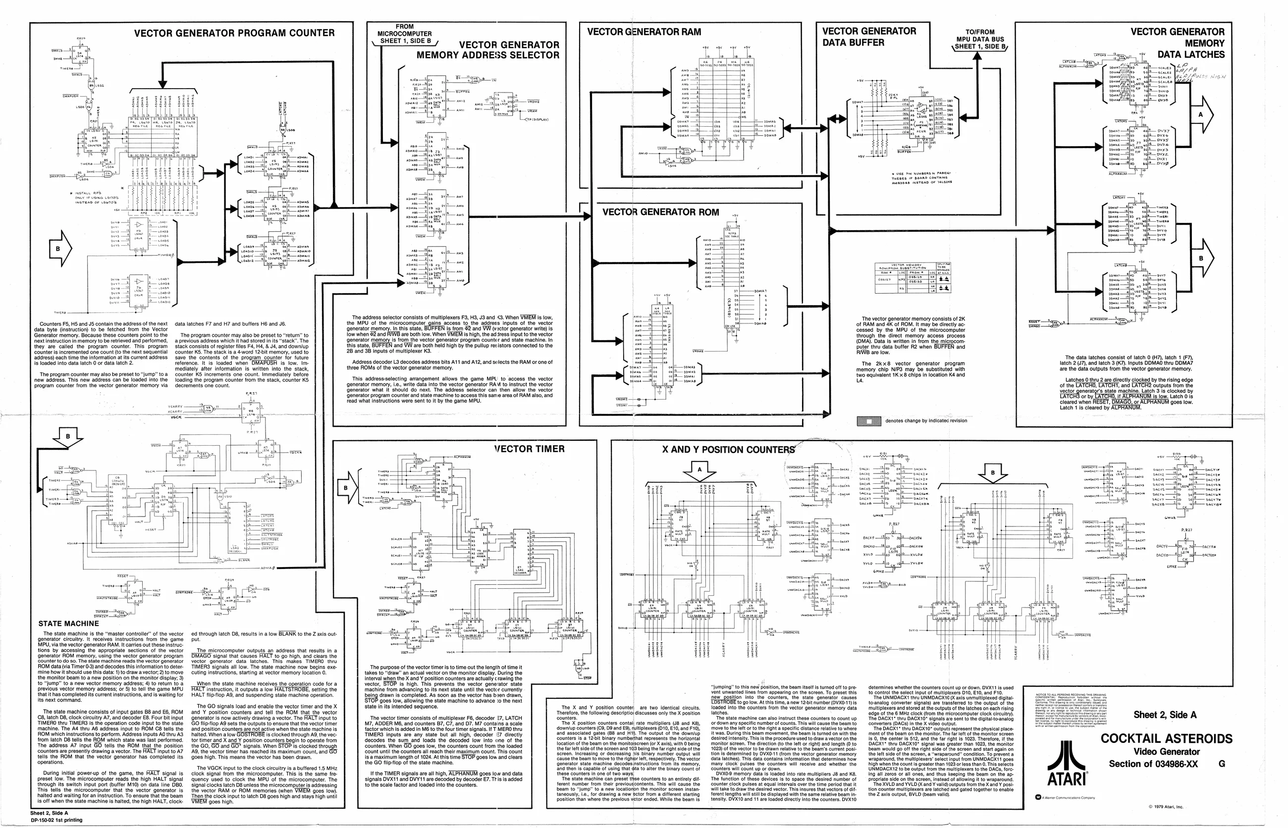
“The adress selector consists of multiplexers F3, HS, J9 and <9. When VHTEM is tow, the MPU‘ ofthe microcomputer grin ‘access to the adress inputs of the vector {onerator memory, In this state, BUFFEN is fom 82 and WW (ctor generator wie) is {ow whan 92 and RW are both iow. When VHEM i high the adres input tothe vector {Jonoratormemon, i rom the vector generator program counter and state machine. n {he state, BUFFEN and VW are both Neld high by the pullupretistors connected tothe 28 an 38 inputs of multiplexer KS ‘The vector generator memory consists of 2K ‘of RAM and aK of ROM. It may be directly ac cessed by the MPU of the microcomputer through the direct memory access process (OMA). Data Is written In from the migrocom- DButer thru data buffer R2 when BUFFEN and IW are low. Counters FS, HS and JS contain the address ofthe next data byte (instruction) to be fetched from the Vector ‘Generator memory. Because these counters point to the next instruction in memory tobe retrieved and performed, they are called. the program counter. This program ‘counter is incremented one count (o the next sequential ‘adgross) each time the information at its current address is loaded into data latch 0 oF data latch 2 data latches F7 and H7 and but He and J6. ‘The program counter may also be preset to “return” to ‘previous address which ithad stored in its "stack". The stack consists of register files F4, H4, & J4, and downlup Counter KS. The stack is a 4word 12bit memory, used to Save the contents of the program counter tor future reference. It is loaded when His. fow. Im mediately after information is written into the stack, Counter KS increments one count. Immediately before Toading the program counter trom the stack, counter KS decrements one count. ‘The data latches consist of latch 0 (H7), latch 1 (F7), latch 2 (7), and latch 3 (K7). Inputs DOMAO thru DDMA7 are the data outputs from the vector generator memory.
Latches 0thru2 are lirectly clocked by the rising edge of tho LATCHO, LATCHT, and ‘utputs frm the Sector generatgr’s stato machine. Latch 31s clocked by ‘orby EATCHO, i ACPHANUM fs ow. Latch O18 cleared when 9088 low. tite tT cared by ALPHANUME. Address decoder L3 decodes address bits A11 and A12, and selects the RAM or one of three ROMs of the vector generator memory The 2kx8 vector generator program memory chip NIP3 may be substituted with {wo equivalent 1K x8 chips in location Ké and Us The program counter may also be preset to jump" toa new address. This new address can be loaded into the program counter from the vector generator memory via ‘This address-selecting arrangement allows the game MPL’ to access th vector ‘generator memory, Le, write data into the vector generator RAM to instruct the vector ‘Generator what it should do next. The address selector can then allow the vector ‘Generator program counter and state machine to access this same area of RAM also, and Fead what Instructions were sent to it by the game MPU.
VECTOR TIMER
pom | acs a : as ee orga i ene iil a
STATE MACHINE
‘The state machine is the “master controller” of the vector generator circuitry. It receives instructions from the game MPU, via the vector generator RAM. Itcarries out these instruc tions by accessing the appropriate sections of the vector {generator ROM memory, using the vector generator program ounter todo so. The state machine reads the vector generator ROM data (via Timer 0) and decodes this information to deter- ‘mine how it should use this data: 1) to draw avector, 2) 10 move the monitor beam to a new position on the monitor display 3) to "jump" to anew vector memory address; 4) to return to a previous vector memory address; or 6) to tell the game MPU ‘that ithas completed its curent instructions, ang is walting for ite next command,
‘The state machine consists of input gates BS and E6, ROM 2, latch 08, clock circultry A7, and decoder E8. Four bit input TTIMERO thru TIMERS Is the operation code Input to the state machine, The A4 thru AB address input to ROM C8 tells the ROM which instructions to perform. Address inputs AO thru A. {rom latch 08 tells the ROM which state was last performed. ‘The address A7 input GO tells the ROM that the position counters are presently drawing a vector. The FACT input to AT tells the ROM that the vector generator has completed its operations.
During initial powerup of the game, the HALT signal is preset low. The microcomputer reads the high HALT signal {through its switch input port (buffer M10) on data line DBO. This tells the microcomputer that the vector generator Is halted and waiting for an instruction. To ensure that the beam {is off when the state machine is halted, the high HALT, clock:
‘Sheet 2, Side A 10P-15002 1st printing 4 through latch 08, results in a low BLANK to the Zaxis out: put
‘The microcomputer outputs an address that results in a BHAGO signal that causes HALT to go high, and cloars the eotor gonerator data latches, This makes TIMERO thru TIMERS signals all low. The state machine now begins exe Cuting instructions, starting at vector memory locaton 0.
When the state machine receives the operation cade for a [HALT instruction, outputs iow HALTSTROBE, sein the HALT flipflop A8, and suspending state machine operation.
‘The GO signals load and enable the vector timer and the X and ¥ postion counters and tell the ROM that the vector Generators now actively crawing a vector, The HALT input to 6 flop AS sets tne Gutputs to ensure thatthe vector timer and postion counters are nat ative when the state machine is hated Winn alow is clocked through AS. the vec: tor timer and X and ¥ position counters begin to operate from the GO, GO and GO" signal, When STOP ts clocked through 49, the vector timer nas reached its maximum count and GO. Goes high, This means the vector has been Grav, ‘The VGOK input to the clock circuitry isa buffered 1.5 MHz clock signal from the microcomputer. This is the same fre- Quency used to clock the MPU of the microcomputer. The signal clocks latch D8 unless the microcomputer is addressing the vector RAM or ROM memories (when {gees low) Then the clock input to latch D8 goes high and stays high until ‘9088 high ‘The vector timer consists of multiplexer FB, decoder £7, LATCH, M7, ADDER MB, and counters 87, C7, and D7. M7 contains a scale facior which is added In MB to the fou timer signals. IT MERO th TIMERS inputs are any st decodes the sum and’ loads the decoded’ low into one of the ‘counters. When GO Count until the counters al reach their maximum count. This count isamaximum length of 1024. At this time STOP goes low and clears the GO flip-flop of the state machine.
signals DVX11 and DVY11 are decoded by decoder €7. Tis is added to the scale factor and loaded into the counter. “The purpose of the vector timer isto time out the length of time. takes to "draw" an actual vector on the monitor display. During the interval when the X and Y position counters are actually crawing the vector, STOP is high. This prevents the vector generator state machine from advancing to its next state until the vector currently boeing drawn is completed. As soon as the vector has b3en drawn, {9028 low, allowing the state machine to advance to the next state in its intended sequence.
bout all high, decoder £7 directly
‘goes low, the counters count from the loaded
nals are all high, ALPHANUM goes low and data otnlup counters (C8, 9 andes fand associated gat {counters 1s-a 12bit binary numbertnat represents the horizontal tocation ofthe beam on the moniteereen (or X axis), with 0 bang ther ‘screen. Incroasing or decreasing nis binary number output vit ear ‘The X and ¥ position counter are two identical circuits. ‘Thoreore, the following description discusses only he X position "Tho X position countors contal ate multipliers (J8 and KE), rultiptexers (010,10, and F10, (G8 and Hi. The output of the downy
it sido of tho seroon and 103 being the fright side of the ighbr lft, respectively. The vector ‘rom lis momory, ne binary count of
“he state machine can preset thse counters to an ently di his wil cause the “jumping” to tis ne position, the beam itelt is turned off to prei unwanted lines ftom appearing on the seroon, To prose the ‘Rew ‘positon Into. the counters, the. stato generator causes ‘EBSTRBEo gotow: At hi time, a now ‘zor aumber(OVX0-1 caged nt the eounters from he vector goerator memory data latches, "Tho state machine can also instruct these counters to count up ‘ordown any specie numberof counts This wil cause the beam to ‘ove tothe lft orto the ght a specific distance relative to wh {Rwas. During this beam movemant, the beam is tuned on with Gesired intensity. This s the procedure used to draw a vector onthe ‘monitor screen. Tha rection (to the lft or right) and tongth (0 t0 1023) of tne vector to be drawn relativ to tho Bea's current post tion Is determined by DVX0-11 (rom the vector gonerator memory ‘ata latches). Ths data contains information that determi many clock pulses tho counters will receive. and wr ‘counters will count up or down, ‘BYX0'8 memory data e loaded into rato multiplier J8 and KB, fon each rising (8490 of the 6 MHz clock (from tho microcomputer clock cout). ‘The DAOXT" thru DAGXI0" signals ae sat tothe digital oanalog ‘Converters (OAC) In the X vidoo outout. “The DACK1” thru DAGXT0" outputs represent the physical place- ‘mont of tho beam on the monitor The far eft ofthe monitor screen Fs00, the conter i512, andthe far ight Is 1028. Therefore, i the DAGXT® thru DACXIO signal was greater than 1023, the monitor beam would go off the right sid of the sereon and start again on the fet sid ofthe screen, a “wraparound” conaltion To prevent @ "show wraparound, the rullipioxer’ Select input from UNMOROX'1 goes ‘the high whoa the counts great than 1028 o ees than 0. The soocts UNMDAGX'2 to be output trom the multiplexers tothe DACS, fore ing all zeres oF all ones, and thus keeping the Dropriate side on the se tion counter multiplexers are ‘the Z axis output, BYLD (boar Vall COCKTAIL ASTEROIDS Video Generator
Section of 034986-XX G ATARI