Battlezone DP-156-3rd-01B
Battlezone (rev 2) (Atari, 1980) · Drawing Package · 1 pages · original scan
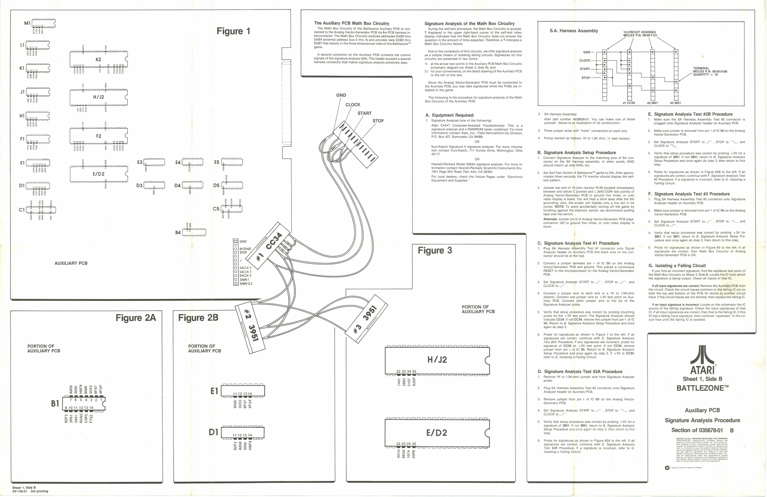
EN] zis Figure 1
E3[, E4|_»
nates
a 3
AUXILIARY PCB [ooo 0000 0000p
PORTION OF AUXILIARY PCB
‘Shoot 1, Side B
DP-156-01 rd printing Figure 2A
\ Figure 2B
PORTION OF AUXILIARY PCB
9569 3U53 9Fa7 4FUF
Di
eget S282 41121314
41121314
The Auxiliary PCB Math Box Circuitry
The Math Box Circuitry of the Battlezone Autliary PCB is con:
nected to the Analog Vector-Generator PCB via fe PCB hamess in:
terconnector. The Math Box Circuitry receives addresses EABO thru
EAB4 (external address bus 0 thru 4) and provices data EDBO thru
E087 that results in the three-dimensional videoot the Battlezone™ signals of the signature analyzer (SA). This header accepts a special
game.
‘A second connector on the Auxiliary PCB ccnnects the control
harness connector that makes signature analysis extremely easy. Signature Analysis of the Math Box Circuitry During the self-test procedure, the Math Box Circuitry is quizzed. T displayed in the upper righthand comer of the self-test video <display indicates that the Math Box Circuitry does not answer the
uestion in the amount of time expected, Therefore, a T indicates a Due to the complexity ofthis circuitry, we offer signature analysis
Math Box Circuitry failure. Due to the complexity ofthis circuitry, we offer signature analysis. 1 a simple means of isolating falling circuits. Signatures for this circuitry are presented in two forms:
- at the actual test points in the Auxiliary PCB Math Box Circuitry ‘schematic diagram (on Sheet 3, Side B), and
- foryour convenience, on the detail drawing of the Au to the left ofthis text ry PCB Since the Analog Vector Generator PCB must be connected to the Auxiliary PCB, you may take signatures while the PCBs are in. stalled in the game,
‘The following is the procedure for signature analysis of the Math Box Circuitry of the Auxiliary PCB:
A. Equipment Required:
- Signature Analyzer (one ofthe following: Aan G*A*T Computer Assisted Troubleshooter. This is a signature analyzer and a RAM/ROM tester combined. For more information contact tar, nc, Feld ServceiCoin Op Division, P.O. Box 427, Sunnyale, CA $4086, oR KureKasch Signature I! signature analyzer, For more informa tion contact KureKasch, 711 Hunter Drive, Wilmington, Ohio 45117, on Hewlett-Packard Model S004A signature analyzer. For more information contact Hewlett-Packard, Scientific Instruments Div 11501 Page Mill Road, Palo Alto, CA 94304. For local dealers, check the Yellow Pages under “Electronic Equipment and Supplies.”
Figure 3
PORTION OF AUXILIARY PCB S.A. Harness Assembly 42.CIRCUIT HOUSING MOLEX P.N. 09.50.7121 \ La eno tock: ry
START stop — [e}-4 A
wncesa TTTT TERMINAL MOLEX P.N. 06-50-0106 QUANTITY = 18
123951 33951
SA Hames Assembly: Atari part number A03683601. You can make one of these Yourself. Above is an illustration ofits construction
Three jumper wires with “hook” connectors on each end.
Pull resistor as flows: 1K to 18K ohm, watt resistor
Signature Analysis Setup Procedure Connect Signature Analyzer to the matching pins of SA con nector on the SA Harness assembly. In other words, GND Should match up with GND, ot.
Set Self-Test Switch of Battlezone™ game to ON. After approx imately three seconds, the TV monitor should display the set test pattern.
Jumper top end of tK-ohm resistor R129 located immediately between and below C [center] and L [left] COIN test points) of ‘Analog Vector-Generator PCB to ground five times, or until, video display is blank. You will hear a short beep after the 5th ‘grounding; also, the screen will display only a tiny dot in its center. NOTE: To avoid accidentally turning off the game by brushing against the interlock switch, we recommend putting tape over the switch. Altemate: Jumper pin 5 of Analog Vector Generator PCB edge ‘connector J20 to ground five times, or until video display is biank.
i}
Signature Analysis Test #1 Procedure Plug SA Hamess Assombly Test #1 connector onto Signal ‘Analyzer header on Auxiliary PCB (the black wire on the con: rector should be at the top).
Connect a jumper between pin 1 of IC B6 on the Analog Vector-Generator PCB and ground. This places a continuous RESET to the microprocessor on the Analog Vector-Generator Pca,
‘Set Signature Analyzer START to _/~ , STOP to /~, and CLOCK to_—
Connect a jumper wire to each end of a 1K to 1.8Kohm resistor. Connect one jumper wire to + SV test point on Aux liary PCB. Connect other jumper wire to the tip of the Signature Analyzer probe.
Verity that setup procedure was correct by probing (touching probe to) the +5V test point. The Signature Analyzer should Indicate CC34.If not CC84, remove the jumper from pint of IC
- Retum to B. Signature Analysis Setup Procedure and once again do step 3
Probe for signatures as shown in Figure 1 to the left. If all signatures are correct, continue with 0. Signature Analysis Test #2A Procedure. f any signatures are incorrect, probe for signature of CC34 on +5V test point. If not CC34, remove jumper from pin 1 of IG 88, Return to 8. Signature Analysis. Setup Procedure and once again do step 3. It + 5V is CC34, refer to G. Isolating a Failing Circut.
Signature Analysis Test #2A Procedure Remove 1K to 1.5K-ohm jumper wice from Signature Analyzer probe.
Plug SA Hames Assembly Test #2 connector onto Signature ‘Analyzer header on Auxiliary PCB.
Remove jumper trom pin 1 of IC 86 on the Analog Vector- Generator PCB,
‘Set Signature Analyzer START to_/— , STOP to“, and CLOCK to_—
Verity that setup procedure was correct by probing +5V for a signature of 3951. If not 3951, return to B. Signature Analysis ‘Setup Procedure and once again do step 3, then return to this, step,
Probe for signatures as shown in Figure #2A to the left. If all signatures are correct, continue with E. Signature Analysis, Test #28 Procedure. It a signature jis incorrect, refer to G. Isolating a Failing Circuit, E. Signature Analysis Test #2B Procedure
- Make sure the SA Hamess Assembly Test #2 connector is plugged onto Signature Analyzer header on Auxillary PCB. 2, Make sure jumper is removed from pin 1 of IC BB on the Analog Vector-Generator PCB,
- Sot Signature Analyzer START to_/— , STOP to CLOCK to 7, and
- Verity that setup procedure was correct by probing +8V for a signature of 3961. If not 3961, return to B. Signature Analysis ‘Setup Procedure and once again do step 3, then return to this, step.
Probe for signatures as shown in Figure #28 to the left. fall signatures are correct, continue with F. Signature Analysis Test #3 Procedure. Ifa signature is incorrect, refer to G. Isolating a Failing Circuit.
F, Signature Analysis Test #3 Procedure Plug SA Hamess Assembly Test #9 connector onto Signature ‘analyzer header on Auxiliary PCB,
- Make sure jumper is removed from pin 1 of IC B6 on the Analog Vector-Generator PCB,
3, Set Signature Analyzer START to_/— , STOP to —\_, and CLOCK to.
- Verity that setup procedure was correct by probing +5V for 3951. If not 3951, return to B. Signature Analysis Setup Pro- ‘cedure and once again do step 3, then return to this step.
‘5. Probe for signatures as shown in Figure 3 to the left. If all signatures are correct, then Math Box Circuitry of Analog Vector-Generator PCB is OK.
G. Isolating a Failing Circuit Ifyou find an incorrect signature, tind the signature test point of the Math Box Circuitry on Sheet 3, Sie B, Locate the IC from which the signature is being output. Check al inputs of that IC Wall input signatures are correct: Remove the Auxiliary PCB from the circuit. Check the circuit traces common to the failing IC pin on booth the top and bottom of the PCB for shorts to another circuit trace. Ifthe cicult traces are not shorted, then replace the falling IC {If an input signature is incorrect: Locate on the schematic the IC ‘source of the failing signature. Check the input signatures of that IC. fall input signatures are correc, then thats the failing IC. If this IChas a failing input signature, then continue “upstream” in the cir. cuit flow until the failing IC is isolated,
A. ATARI Sheet 1, Side B
BATTLEZONE™
Auxiliary PCB
Signature Analysis Procedure
Section of 03567801 B