Warlords DP-175-1st-01A
Warlords (Atari, 1980) · Drawing Package · 1 pages · original scan
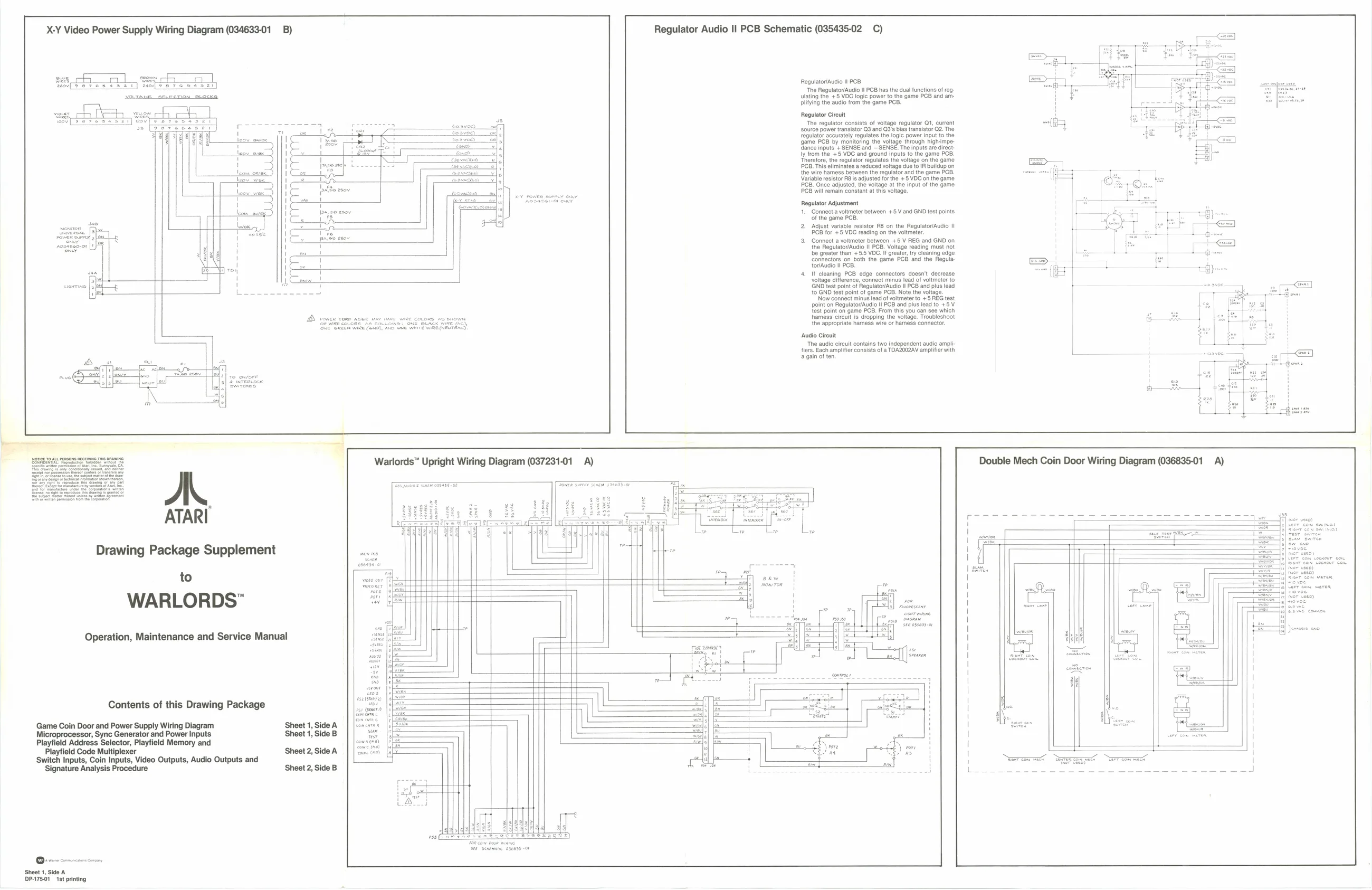
i X-Y Video Power Supply Wiring Diagram (034633-01 _B) Regulator Audio Il PCB Schematic (035435-02 C)
RegulatorAuaio It PCB ‘The Regulato/Audio lt PCB has the dual functions of reg uiating ie + 5 VOC lege power to he game POD an a { plying the audio From the game
aoe =o Regulator Circuit ‘The regulator consists of voltage regulator Q1, current
source power transistor Q3 and 03's bias transistor Q2. The
regulate accurately regulates the logic powet input tothe {game PCB by monitoring the voltage through high-impedance inputs s SENSE and SENSE The nputs are dract |y from the +5 VOC and ground inputs to the game PCB, Therefore, the regulator regulates the voltage on the game
OB. This eliminates a reduced voltage due to IR buildup on
the wire harness between the regulator and the game PCB, Variable resistor RBs adjusted forthe +5 VOC on the game PCB. Once adjusted, the voltage at the input of the game PCB will eemain constant at this voltage. oe ra It
Regulator Adjustment
1. Connect a voltmeter between +5 V and GND test points
of the game PCB, ‘Adjust variable resistor RB on the Regulator/Audio I!
ig PCB for +5 VDC reading on the voltmeter
Connect a voltmeter between +5 V REG and GND on the Regulator/Audio II PCB. Voltage reading must not
be greater than +-5.5 VDC. It greater, try cleaning edge
‘connectors on both the game PCB and the Regula ‘tor/Audio I PCB.
- If cleaning PCB edge connectors doesn't decrease voltage difference, connect minus lead of voltmeter to GND test point of RegulatoriAudio Il PCB and plus lead re to GND test point of game PCB. Note the voltage.
Now connect minus lead of voltmeter to +5 REG test the appropriate hamess wire or harness connector fiers. Each amplifier consists of a TDAZ002AV amplifier with
point on Regulator/Audio ll PCB and plus lead to +5 V fest point on game PCB. From this you can see which harness circuit is dropping the voltage. Troubleshoot the appropriate hamess wire or harness connector. ‘Audio Circuit The audio circuit contains two Independent audio amp
a gain of ten,
Warlords™ Upright Wiring Diagram (037231-01 A) Double Mech Coin Door Wiring Diagram (036835-01 A) A. ATARI
Drawing Package Supplement
to
WARLORDS”
Operation, Maintenance and Service Manual
Contents of this Drawing Package ,
Game Coin Door and Power Supply Wiring Diagram Sheet 1, Side A H Microprocessor, Sync Generator and Power Inputs ‘Sheet 1, Side B i Playfield Address Selector, Playfield Memory and H Playfield Code Multiplexer Sheet 2, Side A \ ‘Switch Inputs, Coin Inputs, Video Outputs, Audio Outputs and ! Signature Analysis Procedure Sheet 2, Side B ‘
Sheet 1, Side A DP-75.01 1st printing