Centipede DP-182-4th-02B
Centipede (revision 4) (Atari, 1980) · Drawing Package · 1 pages · original scan
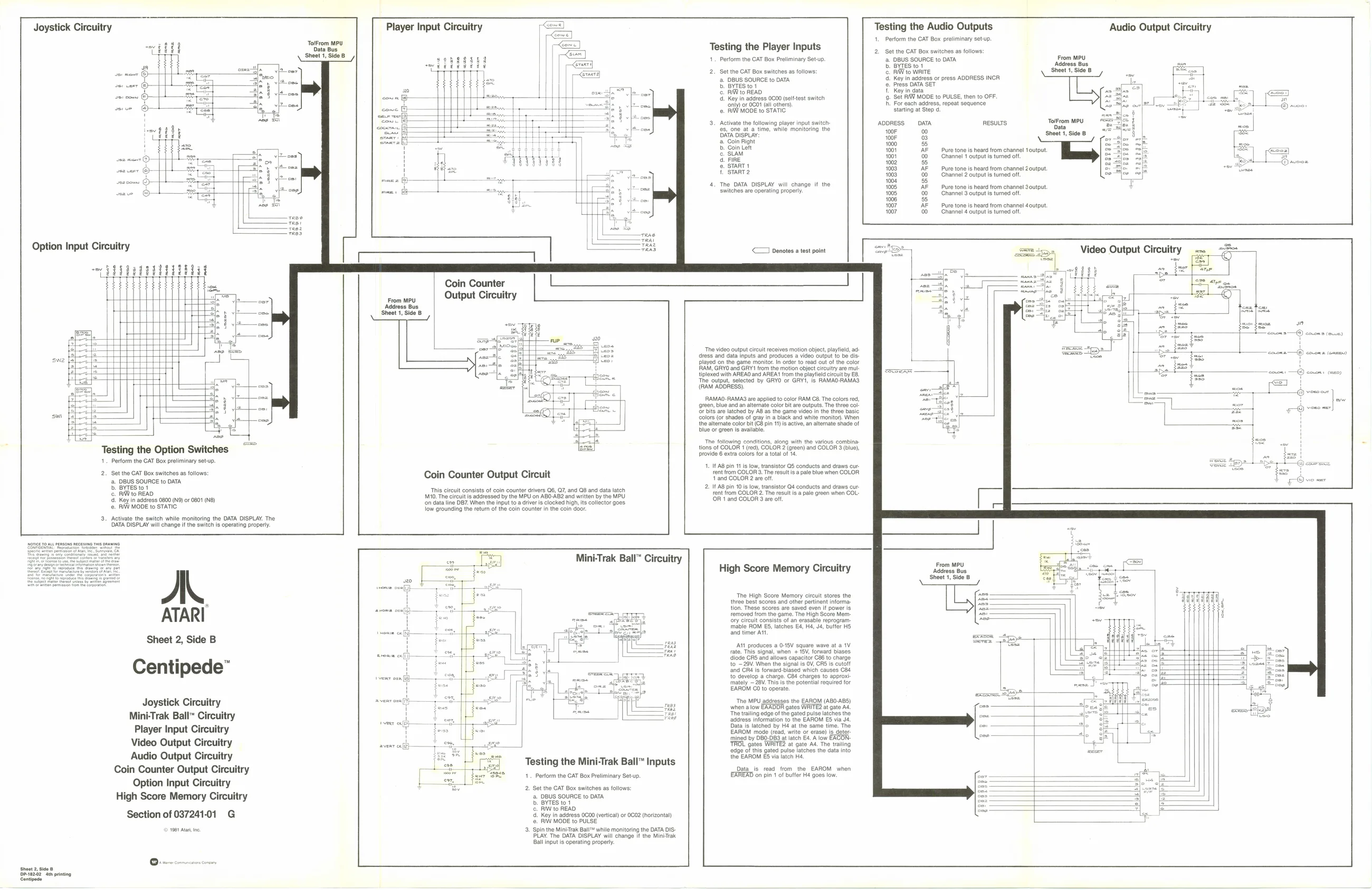
Testing the Audio Outputs Audio Output Circuitry
- Perform the CAT Box preliminary setup.
Joystick Circuitry Player Input Circuitry
bese exe Testing the Player Inputs bra 2. Set the CAT Box switches a follows
| Steet tse: | soRegged | 1. | Perform the GAT Box Preliminary Setup. | a. DBUS SOURCE to DATA | From MPU |
He xara b ByIes to Across Bus
| ; | Gan | 2. | Set the CAT Box switches as follows: | Dane Were | sheet Side 8 | ; |
| 4 | 2. DBUS SOURCE to DATA | ai Key nadaress or press ADDRESS INCR | = | x | ||
| ij | &. BYTESio! | eee ota Set | - |
| © RW to READ invita 4: Key In adress 0000 (slttestswiten 6 Set RI MODE to PULSE, then to OFF
| ‘np oF O00" fall others | 8. For each adcress, repeat sequence | i |
o. RN MODE to STATIC Staring a Stop d :
| 3. | Activate the flowing player input swith | ADDRESS | DATA | RESULTS | ToFrom MPU | : | |
| te, one at a tine, ale mononng the | # | H | |||||
| Seon | or | sheet | Side 8 | 4 | |||
| 2 Com fignt | wor | <1 | im | ||||
| B. ainten | He | asernunamomonenmins | mor | E | BR | aa | |
| crear | oo | 2 | Channa | cubits times | 5 | Gd | [3 |
| 0000 | Chantel2sutput is trned oft | Ey | |||||
| 4, | The DATA DISPLAY wil change if the | 00 | —-AF__-Pure tones heard tom channel output | ||||
| Sedichice ers operating property | 1005 | 00, | Channel 3 output is tuned off. |
eS 100? ——-AF_—_-Pure tones head tom channel output
| or | 00 | Chantel¢sutput ts turned oft |
<= Denotes a test point
"ua Coin Counter
Output Circuitry
wot | moe a cots —@ cases (oe)
‘The video output circuit receives motion object, playtiold a tiplexed with AREAO and AREA’ trom the playfield circuit by EB
dress and data inputs and produces a video output to be displayed on the game monitor. In order to read out of the color RAM, GRYO ang GRY1 from the motion object circuitry are mut tiplexed with AREAO and AREA’ trom the playfield circuit by EB. The output, selected by GRYO or GRY1, is RAMAO-RAMAS (RAM ADDRESS),
RAMAO-RAMA3 are applied to color RAM C8. The colors red,
‘9r28n, blue and an alternate color bit are outputs. The three col
Or bits are latched by AB as the game video in the three basic Colors (or shades of gray in a black and white monitor). When ow
if, the alternate color bit (C8 pin 11) is active, an alternate shade of ir i tions of COLOR 1 (red), COLOR 2 (green) and COLOR 3 (blue),
Dive or green fe avaiable,
1 ‘Tho following conditions, along with the various combina
Testing the Option Switches provide 6 extra colors for a total of 14 1, Perform the CAT Box preliminary set-up. 1. ITAB pin 11 is fow, transistor QS conducts and draws ci
| 21 | got | elon Baten on | Coin Counter Output Circuit | tent om COLOR 3. The results | a pale blue when COLOR |
a o
| D. BYTES tot | Prda-csrill | cies | al | sucatien | cespianxoa | muna | ace | 2. If AB pin 10 is low, transistor Q4 conducts and draws cur | |
| hips | ae | Is circult consists of coin counter drivers | 06, Q7, and | QB and | data latc | Fe | COLO | Tee | ne ree aero |
M10. The circuit is addressed by the MPU on ABO-AB2 and written by the MPU nt a2 The
| Kee In ideas 0600 (0 | of Osc | ‘on data line DB7. When the input to a driver is clocked high, its collector goes. | ‘OH | 6nd COLORS se Ot |
©. RAW MODE to STATIC low grounding the return of the coin counter in the coin door.
- Activate the switch while monitoring the DATA DISPLAY. The DATA DISPLAY will change if the switch is operating properly.
Mini-Trak Ball” Circuitry From MPU Address Bus Sheet 1, Side B
High Score Memory Circuitry
The High Score Memory circuit stores the three best scores and other pertinent informa: tion. These scores are saved even If power is ‘emoved from the game. The High Score Memory circuit consists of an erasable reprogram: mable ROM ES, latches E4, H4, J4, buffer H5 and timer Att Sheet 2, Side B
Centipede” ANI produces a 0-15V square wave at a 1V rate, This signal, when + 18V, forward biases diode CRS and allows capacitor C88 to charge to ~ 29V. When the signal is OV, CRS is cutoff ‘and ORé is forward-biased which causes C84 to develop a charge. C84 charges to approxi mately ~ 28V. Ths is the potential required for EAROM ©0 to operate, Lfslols false
‘The MPU addresses the EAROM (ABO-ABS) when a iow EAADDR gates WRITE? at gate Ad ‘The trailing edge of the gated pulse latches the address information to the EAROM E5 via J4 Data i latched by H4 at the same time. The EAROM mode (read, write or erase) is determined by DB0-D83 at latch E4. A low EACON. ‘TROL gates WRITE? at gate Ad. The tailing edge of this gated pulse latches the data into the EAROM £5 via latch Ha Joystick Circuitry Mini-Trak Ball™ uitry Player Input Circuitry Video Output Circuitry Audio Output Circuitry Coin Counter Output Circuitry Option Input Circuitry
Key in address 0000 (vertical) or 0602 (horizontal Section of 03724101 G @. RW MODE to PULSE _ 1984 Ata ne 3. Spin the MiniTrak Ball™ while monitoring the DATA OIS- PLAY. The DATA DISPLAY will change If the MiniTrak Ball input is operating properly. Testing the Mini-Trak Ball™ Inputs Data is read from the EAROM when
- Perform the CAT Box Preliminary Setup EAREAD on pin 1 of buffer H4 goes low 2, Set the CAT Box switches as follows: a. DBUS SOURCE to DATA b. BYTES to1 ©. RIW to READ
Sheet 2, sae 6 Deez? Ah ping