TX-1 TM-262 1st Printing
TX-1 (World) (Tatsumi (Atari/Namco/Taito license), 1983) · Technical Manual · 88 pages · 74 sections · original scan
*TX1 is manufactured by Atari, Inc. under license from Namco. TM and © Namco 1985
Atari Customer Service
Ifreading through this manual does not lead to solving a certain maintenance problem, call TELEHELP® at the Atari Customer Service office in your geographical area, as shown below.
UNITED STATES
Parts and Service
Atari, Inc. California Customer Service Office 737 Sycamore PO. Box 906 Milpitas, CA 95035 Telex 17-1103 (Monday-Friday, 7:30-4:00 pm Pacific Time)
zs From California, Alaska, or Hawaii
(408) 943-1120 = From anywhere else in the continental United States toll-free (800) 538-1611
EUROPE
Parts and Service
Auri Ireland Limited European Customer Service Office Tipperary Town, Ireland Telex 28165 (Monday-Friday, 9:00-6:00 pm GMT) BS 062-52155
This page is a drawing, shown as the original scan.
TX1
© 1984 by Atari, Inc. All rights reserved. No part of this publication may be reproduced by any mechanical, photographic, or electronic process, or in the form ofa phonographic recording, nor may it be stored in a retrieval system, transmitted, or otherwise copied for public or private use, without permission from the publisher. The game play, all graphic designs, this technical manual, its accompanying schematic diagrams, and the display manual are protected by the U.S. Copyright Act of 1976. This Act provides for increased penalties for violating federal copyright laws. Courts can impound infringing articles while legal action is pending. If infringers are convicted, courts can order destruction of the infringing articles. In addition, the Act provides for payment of statutory damages of up to $250,000 in certain cases. Infringers may also have to pay costs and attorneys’ fees and face an imprisonment of up to five years. Atari will aggressively enforce its copyrights against any infringers. We will use all legal means to immediately halt any manufacture, distribution, or operation of a copy of video games made by us. Anyone who purchases such copies risks forfeiting such a game.
Published by: Atari, Inc. 790 Sycamore Drive PO. Box 906 Milpitas, California 95035
Printed in the U.S.A. 3N
TX1
Notice Regarding Non-ATARI Parts
Use of non-ATARI parts or modifications of any ATARI® game circuitry may adversely affect the safety of your game, and may cause injury to you and your players.
You may void the game warranty (printed on the inside back cover of this manual) if you do any of the following: © Substitute non-ATARI parts in the game. © Modify or alter any circuits in the game by using kits or parts nor supplied by Atari.
NOTE
This equipment generates, uses, and can radiate radio frequency energy and if not installed and used in accordance with the instruction manual, may cause interference to radio communications. It has been tested and found to comply with the limits for a Class A computing device pursuant to Subpart J of Part 15 of Federal Communications Commission (FCC) Rules, which are designed to provide reasonable protection against such interference when operated in acommercial environment. Operation of this equipment in a residential area or modification to this equipment is likely to cause interference in which case the user, at his own expense, will be required to take whatever measures may be required to correct the interference. If you suspect interference from an ATARI® game at your location, check the following: All green ground wires in the game are properly connected as shown in the game wiring, diagram, The power cord is properly plugged into a grounded three-wire outlet. The game printed-circuit boards (PCB) are properly installed within the Electromagnetic Interference (EMI) cage. The EMI Shield PCB is properly installed and connected in series with the game PCB harness. All filter capacitors required on the EMI Shield PCB are properly soldered in place. If you are still unable to solve the interference problem, please contact ATARI Customer Service. See the inside front cover of this manual for service in your area.
iii
TX1
Table of Contents
Set-Up Game Overview . Installation .... Switch Information . . Selecting the Game Options . Game Play
Self-Test Performing the SelfTest . .
Maintenance Preventive Maintenance . . Lubricating the Steering Control . . Lubricating the Shift Control Lubricating the Foot-Pedal Control .. .
Corrective Maintenance ................... 066.0000 2 eee Removing the Steering Control Disassembling the Steering Control . Removing the Shift Control Disassembling the Shift Control Removing the Foot-Pedal Controls . Disassembling the Foot-Pedal Control . . .
4 Illustrated Parts Lists For a list of all illustrations in this manual, see the following page. 1-2 1-2 1-4
1-6
3-2 3-2 3-2
3-4 3-4 3-4 3-6 3-6 3-6 3-6
List of Illustrations
Figure 1-1 Figure 1-2
Figure 2-1 Figure 2-2 Figure 2-3 Figure 2-4
Figure 3-1 Figure 3-2 Figure 3-3 Figure 3-4
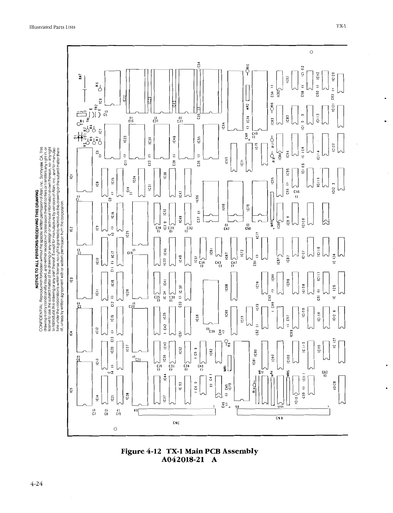
Figure 4-1 Figure 4-2 Figure 4-3 Figure 4-4 Figure 4-5 Figure 4-6 Figure 4-7 Figure 4-8 Figure 4-9 Figure 4-10 Figure 4-11 Figure 4-12 Figure 4-13 Figure 4-14 Figure 4-15 Figure 4-16
Table 1-1 Table 1-2 Table 1-3 Table 1-4
Table 2-1 Table 3-1 Stabilizing the Sit-Down Cabinet 1-3 Assembling the Sit-Down Cabinet .... 15
Screen 1—RAM/ROM Test Passes 2-2 Screen 1—RAM/ROM Test Fails . 2-2 Screen 2—Color-Bar Pattern. » 23 Screen 3—Crosshatch Pattern 2.6.0.0. e eee eee 2-4
Lubricating and Disassembling the Steering Control............. 3-3 Tightening the Steering-Control Cap Screws .... 3-4 Disassembling and Lubricating the Shift Control . 345 Lubricating and Disassembling the Foot-Pedal Control 3-7
Illustrated Parts Lists Cabinet-Mounted Assemblies 42 Steering-Wheel Control Assembly . 4-6 Foot-Pedal Control Assembly ...... . tage . 48 Shift Control Assembly Fluorescent Tube Assembly . Utility Panel Assembly Control Controls, Inc. Coin Door Assembly Coin Acceptors, Inc, Coin Door Assembly . Linear Power Supply Assembly Step-Down Power Supply Assembly +12Volt Power Supply Assembly. . 7 TX-1 Main Printed-Circuit Board Assembly... . TX Graphics Printed-Circuit Board Assembly . . TX-1 Sound Printed-Circuit Board Assembly .. : TX-1 EMI Shield Printed-Circuit Board Assembly . . . : TX-1 Audio Printed-Circuit Board Assembly ...............0005
List of Tables
Installation Specifications 1-2 Hardware Kit Contents. . . : 12 Switch Settings for Coin and Credit Options bees 1-6 Switch Settings for Game Difficulty, Time, and Bonus ‘Adder : 16
RAM/ROM Circuits Tested 23 Preventive Maintenance Intervals . 3-2 TX1
TX1
vi
Safety Summary
The following safety precautions apply to all game operators and service personnel. Specific warnings and cautions will be found throughout this manual where they apply.
A WARNING A
Properly Ground the Game. Players may receive an electrical shock if this game is not properly grounded! To avoid electrical shock, do not plug in the game until it has been inspected and properly grounded. This game should only be plugged into a grounded 3-wire outlet. If you have only a 2-wire outlet, we recommend you hire a licensed electrician to install a grounded outlet. Players may receive an electrical shock if the control panel is not properly grounded! After servicing any parts on the control panel, check that the grounding clip is firmly secured to the metal tab on the inside of the control panel. Only then should you lock up the game. AC Power Connection. Before connecting the game to the AC power source, verify that the proper voltage-selection plug is installed on the game’s power supply. Disconnect Power During Repairs. To avoid electrical shock, disconnect the game from the AC power source before removing or repairing any part of the game. When removing or repairing the video display, extra precautions must be taken to avoid electical shock because high voltages may exist within the display circuitry and cathoderay tube (CRT) even after power has been disconnected. Do not touch internal parts of the display with your hands or with metal objects! Always discharge the high voltage from the CRT before servicing this area of the game. To discharge the CRT: Attach one end of a large, well-insulated, 18-gauge jumper wire to ground. Momentarily touch the free end of the grounded jumper to the CRT anode by sliding it under the anode cap. Wait two minutes and discharge the anode again. Use Only ATARI Parts. To maintain the safety integrity of your ATARI game, do not use non-ATARI parts when repairing the game. Use of non-ATARI parts or other modifications to the game circuitry may adversely affect the safety of your game, and injure you or your players. Handle Fluorescent Tube and CRT With Care. If you drop a fluorescent tube or CRT and it breaks, it may implode! Shattered glass can fly six feet or more from the implosion. Use the Proper Fuses. To avoid electrical shock, use replacement fuses which are specified in the parts list for this game. Replacement fuses must match those replaced in fuse type, voltage rating, and current rating. In addition, the fuse cover must be in place during game operation.
Properly Attach All Connectors. Make sure that the connectors on each printedcircuit board (PCB) are properly plugged in. Note that they are keyed to fit only one way. If they do not slip on easily, do not force them. A reversed connector may damage your game and void the warranty.
To avoid electrical shock, do not plug in the game until it has been inspected and properly set up for the line voltage in your area. This game should only be connected to a grounded 3-wire outlet. If you have only a 2wire outlet, we recommend you hire alicensed electrician to install a grounded outlet. Players may receive an electrical shock if this game is not properly grounded. Do not touch internal parts of the display with your hands or metal objects!
Set Up
This manual, written for game operators and service technicians, describes your new ATARI game. Chapter 1 contains game assembly and inspection procedures, game specifications, switch information, and option information. Chapter 2 contains self-test procedures. Chapter 3 contains maintenance and repair procedures for the steering wheel, gear shifter, and foot-pedal assembly. Chapter 4 contains illustrated parts lists. Schematic diagrams of the game circuitry are included as asupplement to this manual.
Chapter 1
Set Up
Game Overview
TX1* is a sensational new driving game for one player. With three video displays, the player is literally surrounded by the game graphics. TX-1 game graphics and sounds are so realistic that the player experiences the dangers of real speedway racing. Depending upon the course selected, the race takes place in cities, mountains, or snow country. The player's goal is to increase his skill and speed on each speedway course, and finish the three main stages of the game.
New Features TX-I’s new features are:
- Three video displays show the action of demanding and challenging speedways. © Four-channel sound simulates the realistic sounds of driving a race car.
Installation
TX is shipped from the factory in three sections: the main cabinet assembly, seat assembly, and the header assembly. The main cabinet assembly contains the video displays, coin door, player controls, power supplies, one speaker, four fluorescent tubes, and game printed-circuit boards (PCBs). The seat assembly includes the seat and three speakers, The header assembly rests between the main and seat assemblies, and encases four fluorescent tubes and two attraction panels.
Do not plug in your TX-1 game until it has been inspected and steps 1 through 11 of Assembling the TX-1 Cabinet have been completed.
Table 1-1 Installation Specifications
Characteristic Specification
Power Consumption 500 W Nominal ‘Temperature +5° to +38° C(+37° to +100° F) Humidity Not to exceed 95% relative Line Voltage 100 to 132 VAC (or 200 to 264 VAC) Width 55 in, (139.7 cm) Length 73 in. (184.9 cm) Height 71.4 in. (181.4 cm) ‘Weight 650 Ibs. (294.8 kg)
*TX-1 is created by Tatsumi, manufactured by Atari, Inc. TM and © Namco
1983 in Western Hemisphere. All rights reserved. TM and © Taito 1983 in
entire world except Japan and Western Hemisphere. All rights reserved.
1-2 TX
Inspecting the Game Inspect your game carefully to ensure that it was delivered in good condition. Examine the exterior of each section of the game for dents, chips, or broken parts. 1, Unlock and remove the upper and lower rear access panels of the main cabinet assembly.
- Unlock and open the coin doors. From the coin box, remove the package that contains the hardware for assembling the cabinet. Refer to Table 1-2 to check the contents of your hardware package.
- Inspect the interior of the game as follows: a. Ensure that all plug-in connectors (on the game harnesses) are firmly plugged in. Replug any connectors found unplugged. Do not force connectors together. The connectors are keyed so they only fit in the proper orientation. A reversed edge connector may damage a printed-circuit board (PCB) and will void your warranty. b. Ensure that all plug-in integrated circuits on each PCB are firmly plugged into their sockets. See Chapter 3 for PCB removal instructions. c. Remove the tie-wrap that secures the coiled power cord inside the cabinet. Inspect the power cord forany cuts or dents in the insulation. If required, repair or replace the power cord. Place the square strain-relief plate in the wood slot at the bottom of the power-cord access opening. d. Inspect the power supplies. Make sure the harnesses are plugged in correctly. e. Inspect other major subassemblies, suchas the control panel, video displays, EMI cage, fluorescent tubes, and each PCB. Make sure they are mounted. securely and that all green ground wires are firmly connected.
Table 1-2 Hardware Kit Contents
Quantity Description
13 %-20 x 2-Inch Machine Screw 13 %-Inch Split Lock Washer 13 % -Inch Fender Washer 4 #10-24 x 1-Inch Button Head Machine Screw 4 #10 Flat Washer 4 #10 Lock Washer 1 Header Attraction/Seat Cap
Stabilizing the Cabinet Before assembling your TX-1 game, stabilize the main cabinet assembly and seat assembly to prevent players from rolling the game out of position. The main cabinetassembly
TX1
has six adjustable glides and the seat assembly has four adjustable glides. Before adjusting the glides, position the seat assembly near the notch at the base of the main cabinet assembly. To stabilize the main cabinet assembly, lift one side and place a block of wood, a book, or another object at least 2 inches thick under the raised seat assembly. Partially unscrew the glides until they extend below the casters (see Figure 1-1). Lower the main cabinet assembly and lift the other side. Partially unscrew the adjustable glides until they extend below the casters. Lower the main cabinet assembly. Repeat the above procedure for the seat assembly and unscrew the glides approximately two inches. Assembling the TX-1 Cabinet ‘We recommend that two people perform the following procedures in an area of at least 75 square feet. Refer to Figure 1-2 while assembling the game. 1, Slide out the top seat panel and remove the lower seat panel of the seat assembly.
- Pullthe speaker harness connector through the hole at the base of the seat assembly. set Up
Position the seat assembly near the main cabinet assembly and connect the speaker harness to the main cabinet harness. Carefully slide the seat assembly into the main cabinet assembly until the cleat on the seat assembly slides into the notch at the base of the main cabinet. Be careful not to pinch the speaker harness wire. DO NOT install the screws yet. Insert the rear end of the header assembly into the opening at the top of the main cabinet (make sure the fluorescent tube harnesses are pushed aside) and lower the front end of the header assembly into the top of the seat assembly. Use four 2-inch screws, fender washers, and lock washers to attach the header assembly.
From the back of the main cabinet assembly, use two 2-inch screws, flat washers, and lock washers to attach the rear of the header assembly to the main cabinet (through the upper access area of the main cabinet assembly). Use two button-head screws, flat washers, and lock washers to install the cap on the top of the seatassembly.
Adjustable Gtide
Figure 1-1 Stabilizing the Sit-Down Cabinet
Set Up
- Use three 2-inch screws, fender washers, and lock washers to secure the seat assembly to the main cabinet assembly. These screws are installed through the lower seat panel into the base of the main cabinet assembly (see Figure 1-2).
- From inside the right attraction-panel area of the main cabinet assembly, pull the fluorescent light harness through the hole. Attach both fluorescent light harness connectors to the header assembly harness connectors. ll. Ensure that all fluorescent tubes are installed correctly. Plug the game into a grounded 3-wire outlet. If the fluorescent tubes light, go to the next step. If they do not, recheck the harness connectors. If necessary, replace any damaged fluorescent tube(s). 12, After you have made certain that every fluorescent tube lights, unplug the game.
- Slide each attraction panel and decal into the groove of the header assembly. 14, Place the retainers over the attraction panels.
- Use three 1% -inch button-head screws, lock washers, and flat washers to secure the retainers.
- Slide each attraction panel and decal into the lower retainer of the main cabinet assembly.
- Place the upper retainers over the attraction panels.
- Use three 1-inch button-head screws, lock washers, and flat washers to secure the retainers.
Switch Information
Utility Panel Switches The volume controls, coin counter(s), self-test switch, and auxiliary coin switch are on the utility panel. The utility panel is located inside the upper coin door (see Figures 4-1 TX1
and 4-6). Each volume control adjusts the level of sound produced by one sound channel of the game. The coin counter(s) records the number of coins entered into the game. The self-test switch initiates the Self-Test Mode. The auxiliary coin switch credits the game,
Option Switches
Two dual-inline-package (DIP) switches are located on the Sound PCB at locations 6P and 8P (see Figure 4-13). Switch 6P consists of six toggle switches and switch 8P consists of eight toggle switches. Use these switches to select different pricing and game play options. See Tables 1-3 and. 1-4 for option information.
Selecting the Game Options
¢ The DIP switch at location 6P is for selecting coin and credit options. These options include credits per coin, and coin multipliers for the right and left coin mechanisms.
- The DIP switch at location 8P is for selecting game difficulty levels, seconds of play, and free play. Options preset at our American factory are shown by the “4 symbol. To verify option settings, refer to Chapter 2.
TX Set Up
Header Attraction Panel Screw Lock Washer Flat Washer \ 1 Ni Ser
Main Cabinet bd Lock Washer
Attraction Panel Fender Washer
Upper Access Panel
Video Display | Header Assy
Steering Control Assy Control Panel Assy
Main Cabinet Assy
Main Cabinet Harness:
‘Speaker Harness
Do not plug in the game unti it has
been inspected and assembled, This Top Seat Panel
game should only be connectedtoa grounded 3-wire outlet. If you have only a2-wire outiet, we recommend you hire a licensed electrician to in-
stall a grounded outlet. Players may NOTE
receive an electrical shock if this Foritems with serial number labels, game is not properly grounded! refer to Figure 4-1.
Figure 1-2 Assembling the Sit-Down Cabinet
Set Up TX1
Table 1-3 Switch Settings for Coin and Credit Options
Settings of 8-Toggle Switch on TX-1 Sound PCB (at location 6P)
| 2 | 3 | 8 | |||
| 1 | 4 | 5 | 6 | 7 | Option |
Game Cost
| On | On | 1 Coin Unit for 1 Credit |
Off On 2 Coin Units for 1 Credit
On Off 3 Coin Units for 1 Credit
| Off | Off | 4 Coin Units for 1 Credit | ||
| od | nol | ae} | ||
| & | g | 8g | Left Coin Mechanism | |
| On | » | > | 2 | 1 Coin for 1 Coin Unit<¢ |
| Off | 2 | gs | s | 1 Coin for 2 Coin Units |
Right Coin Mechanism
| On | On | 1 Coin for 1 Coin Unit |
Off = On 1 Coin for 4 Coin Units
On off 1 Coin for 5 Coin Units
| Off | Off | 1 Coin for 6 Coin Units |
Table 1-4 Switch Settings for Game Difficulty, Time, and Bonus Adder
| 1 | 4 | 5 | 6 | 7 |
Settings of 8-Toggle Switch on TX-1 Sound PCB (at location 8P) 2 3 ) 8 Option
| On | On | On |
Off On On
On Off On
| Off | Off | On |
| On | On | Off |
| Off | On | Off |
| On | Off | Off |
| Off | Off | Off |
On On Off On On Off Off Off
On On Off On On Off Off Off On On Off On On Off Off Off Game Difficulty Level A (Easiest) B Cc Da
E F G H (Hardest)
Game Times A (Longest) B ca D (Shortest)
Bonus Adder On No Bonus On 2 Coin Units for 1 Credit On 3 Coin Units for 1 Credit On 4 Coin Units for 1 Credit Off 5 Coin Units for 1 Credit Off 4 Coin Units for 2 Credits Off Free Play Off No Bonus<4
4 Manufacturer's recommended settings for American-made games
Game Play TX-1 is a one-player game with three color raster-scan video displays. Each speedway has three main stages: First Stage, Extended Stage, and Gran Prix Stage. The player will see mountains, deserts, skyscrapers against the skyline, dark tunnels, snow country, and meadows. The player drives a red Formula-1 race car. Upon completion ofeach stage, the player automatically enters the next one. Player controls consist of steering, shift, accelerator, and brake. The object of the game is to finish all three main stages. TX-1 has four modes of operation: Attract, Play, High- Score, and Self-Test. Self-Test is a special mode for checking the game switches and computer functions. You may enter the Self-Test mode from any other mode.
TX1
Attract Mode The Attract Mode begins either when you plug the game in or after exiting from the Play, High-Score, or Self-Test Modes. The Attract Mode ends either when the correct amount of credit is inserted, or when the Self-Test Mode is entered. When the Attract Mode begins, the left screen displays the highest score achieved for each country. The right screen displays the eight highest overall scores. Eight countries are represented by the letters A through H. The player must finish the three main stages to get into one of the countries. The countries are: A = Africa E = Spain B= USA. F = Monaco C = Japan G = Belgium D = France H = Italy The center screen first displays the layout of Stage 1 and. then simulates game play. During game-play simulation, six cars are shown at the starting line. The player drives a red Formula-l racing car. The starting light flashes to green and the race begins. The race continues until the player’s car crashes into another car and explodes. The car reappears on the screen and continues until it hits a sign on the side of the road. Again, the car explodes. During this sequence, the message GAME OVER appears in the center of the screen.
Play Mode
The Play Mode begins when the correct amount of coins are inserted into the coin mechanism(s). The game begins with the player’s car behind the starting line with six other cars and with 70 game seconds (B setting) showing on the clock. Racing hazards include sharp turns, roadside trees, other racing cars, and road signs. As the race progresses, more cars appear on the track. If the player’s car hits another car, road sign, or tree while in HI gear, his car is destroyed in an explosion and racing seconds are lost. The player’s car reappears and the race continues. If the player's car hits another car while in LOW gear, he will spin out. When approaching turns, the player must ease up on the accelerator pedal (or use the brake pedal) to make the corner. The player jockeys for position with the other racers, keeping his eye on the clock at the top center of the middle screen. When time runs out, the race is over. Upon completion ofa stage, the seconds remaining are added to the next stage. While TX-1 is in Play Mode, the right screen displays the number of cars passed, using one star to represent each passed car. The left screen displays the checkpoint map, the high score, and the player’s score. The player should refer to the 7X-I Course Maps chart (located above the center video screen) for checkpoint and country locations. Set Up
First Stage. This stage is comprised of Stage 1. The player must complete Stage 1 in 70 game seconds (B setting) to reach the Extended Stage. At the checkpoint of the Extended Stage, the player must make a decision. If he veers to the right, the course takes him to either Spain, Monaco, Belgium, or Italy. If the player drives to the left, the course takes him to either South Africa, U.S.A., Japan, or France. Extended Stage. This stage is comprised of Stage 2 and Stage 3. The player must complete Stage 2 in 60 game seconds (B setting) and Stage 3 in 50 game seconds (B setting). At the checkpoint of Stages 2 and 3, the player again must decide whether to go left or right. Gran Prix Stage. This stage is comprised of Stage 4 and Stage 5. The player must drive through Stage 4 in 60 game seconds (B setting) and Stage 5 in 60 game seconds (B setting). The final checkpoint is at the end of Stage 4. At this checkpoint the player must go straight ahead to drive through Stage 5.
Hints for Game Play
- Accelerate and stay ahead of other racers. ¢ When cornering, stay to the inside of the track. © When sliding, ease up on the accelerator. © Driving off the track slows the car down.
High-Score Mode
The High-Score Mode begins when a player has earned one of the highest scores. The player has ten seconds to record his initials. A player rotates the steering wheel to locate his initial and presses the accelerator pedal to place his initial on the screen. The third time the pedal is pressed, his initials are transferred into the High-Score Table.
Self-Test Mode
The Self-Test Mode can be entered from all other game modes by pressing the self-test switch on the utility panel. Self-Test allows checking of game switches, potentiometer adjustments, hardware failures, and video-display adjustments. See Chapter 2 for complete self-test information.
This page carries no recoverable text. It is a drawing or a photograph. See the original scan.
Self-Test Procedure
This game will test itself and provide data to show that the game circuitry and controls are operating properly. Selftest data is presented visually on the video display and . audibly through the speakers. No additional equipment is required. We suggest you perform a self-test when you first set up, each time you collect money, change the game options, or 4 suspect game failure. :
Chapter 2
Self-test
Performing the Self-Test
- mation as discussed in the following Self-Test Mode description. Refer to the description for Screen 1 to determine which random-access memory (RAM) or read-only memory (ROM) circuit failed. The game will continue to indicate an error until the faulty circ repaired.
Three self-test screens provide information to indicate the condition of the random-access memory (RAM) and readonly memory (ROM); the accelerator, brake, steering, and shift controls; the sound circuitry; the option-switch settings; and the display circuits. When the self-test switch is turned on during the Attract Mode, the game enters the Self-Test Mode. Turning the self-test switch offat any time during the Self-Test Mode returns the game to the Attract Mode. The following self-test screens are arranged in the sequence in which they occur. After Screen 3, the self-test switch must first be turned off until the Attract Mode display appears, and then turned on again to obtain Screen 1.
Screen 1 Select the Self-Test Mode by turning the self-test switch (located on the utility panel) to the on position. If the selftest passes, Screen 1 appears on the center display as shown in Figure 2-1. If the test fails, Screen 1 appears as shown in Figure 2-2A, and fault location information appears on the right-hand display as shown in Figure 2-2B.
HARD WARE GoOoD
ACCEL >
BRAKE 0 STEERING o SHIFT Low SOUND
| 4 | COIN | UNITS | 1 | GAME | CRE |
LEFT ceay, MECH.
| 1 | COIN | 1 | COIN | UNT? |
| RIGHT | COIN | MECH. | 4 | |
| 1 | COIN | 1 | COIN | UNIT |
NO BONUS GAME RANK B GAME TIME D 't11GH SCORE CLEART Is
Figure 2-1 Screen 1—RAM/ROM Test Passes
2-2 TX1
| HARD | WARE | BAD | 18 |
TePaic k VELERING SHIFT SOUND
| COIN | UNITS | 1 | GAME |
LEFT COIN MECH.
| 1 | COIN | 1 | COIN |
| RIGHT | COIN | MECH. | |
| 1 | COIN | 1 | COIN |
NO BONUS GAME RANK B GAME TIME D
A Center Display
- LOCATION NUMBER OF Ic - (Ob jest gelrf PweB NO. re013 icoe190
B
Right-Hand Display
Figure 2-2 Screen 1—RAM/ROM Test Fails
The following is a description of the displayed information. ¢ HARDWARE indicates the condition of the game RAM and ROM. If the test passes, GOOD is displayed to the right of HARDWARE. If the test fails, BAD is displayed to the right of HARDWARE with a status number that indicates which RAM or ROM circuit is faulty. Specific fault location information appears on the right-hand display: PWB indicates the printed-circuit board number (TCXXX) and NO. indicates the RAM or ROM number (ICXXX) in the circuit that failed. The RAM or ROM number only points to the circuit that failed; the RAM or ROM itself may not be the cause of the error indication. Refer to Table 2-1 fora list of status numbers with a description of the corresponding RAM and ROM circuits tested.
TX1
Table 2-1 RAM/ROM Circuits Tested
Status No. Description
1 Main Microprocessor RAM 2 Video RAM 3 Common RAM 4 Sound RAM 5 Main Microprocessor ROM 6 Sound ROM 7 Not Used 8 Not Used 9 Not Used 10 Interface ROM (Time-Qut Error) iL Common RAM (Access for Arithmetic Microprocessor) 12 Common RAM (Access for Arithmetic Microprocessor) 13 Arithmetic RAM 14 Common RAM (Access for Arithmetic Microprocessor) 15 Object RAM 16 Arithmetic ROM 7 Data ROM (Checksum) 18 Arithmetic Unit
ACCEL checks the operation of the accelerator foot pedal. The number to the right of ACCEL should increase from 0 to F as the foot-pedal is pressed. A brightened F should appear when the foot-pedal is at the bottom limit. BRAKE checks the operation of the brake foot pedal. The number to the right of BRAXE should increase from 0 to F as the foot-pedal is pressed. A brightened F should appear when the foot-pedal is at the bottom limit. STEERING checks the operation of the steering wheel. The number to the right of STEERING should increase from 0 to FF repeating as the steering wheel is turned continuously clockwise and decreasing as the steering wheel is turned counterclockwise. SHIFT checks the operation of the shift control. LOW should appear to the right of SHIFT with the shift control in the up position and HIGH should appear in the down position. SOUND checks the operation of the sound circuitry. Each game sound is selected by pressing the auxiliary coin switch (located on the utility panel behind the coin door). The number of each sound from 0 to IF is displayed to the right of SOUND. Activate the left coin mechanism to hear the sounds selected by the auxiliary coin switch. 3COIN UNITS 1 GAME CREDIT indicates the number of coins that must be deposited in the left or right coin mechanism for one game credit. The number of coins required is selected by the option switches (see Chapter 1). Self-Test
© LEFT COIN MECH. and 1 COIN I COIN UNIT indicates the number of coins that must be deposited in the left coin mechanism for each coin unit. The number of coin units given for each coin deposited in the left coin mechanism is selected by the option switches (see Chapter 1). *® RIGHT COIN MECH. and I COIN 1 COIN UNIT indicates the number of coins that must be deposited in the right coin mechanism for each coin unit. The number of coin units given for each coin deposited in the right coin mechanism is selected by the option switches (see Chapter 1).
- NO BONUS indicates that no bonus game credits are given for additional coins deposited in the coin mechanism. FREE PLAY indicates that the game credits are given without charge by pressing the accelerator foot pedal. The bonus game credits given for additional coins and free play is selected by the option switches (see Chapter I). © GAME RANK indicates the game difficulty from A to H selected by the option switches (see Chapter 1). *© GAME TIME indicates the game times from A to D selected by the option switches (see Chapter 1). HIGH SCORE CLEARED indicates that the scores in the high-score table have been cleared (reset) to the starting scores. All the high scores can be reset by pressing the accelerator foot-pedal and the auxiliary coin switch simultaneously.
Screen 2 Place the shift control in the LOW position and turn the self-test switch off, then on again, to obtain Screen 2 on each display as shown in Figure 2-3. Use this screen to check or adjust the display color (see the display manual for troubleshooting and color adjustment procedures.)
Light Blue
Figure 2-3 Screen 2—Color-Bar Pattern
2-3
Self-Test TX1
Screen 3 Place the shift control in the H/GH position to obtain Screen 3 on each display as shown in Figure 2-4. Use this screen to check and adjust the display convergence. (See the display manual for troubleshooting and convergence adjustment procedures.)
Figure 2-4 Screen 3—Crosshatch Pattern ‘Turn the self-test switch off and wait for the Attract Mode display. Then turn the self-test switch on again to obtain Screen 1.
2-4
Maintenance
The maintenance procedures provided in this chapter are for those items which are subject to the most severe use. To assure the maximum trouble-free operation from this game, Atari recommends that periodic routine maintenance be performed on the game components described in the following procedures. How often routine maintenance is performed depends upon the game environment and frequency of play.
Chapter 3
Maintenance TX1
Preventive Maintenance
This chapter includes preventive and corrective maintenance procedures for the steering, shift, and foot-pedal controls. Atari recommends that periodic preventive maintenance be performed as described in this chapter. References are provided to Chapter 4, Illustrated Parts Lists, to aid in locating the parts that are mentioned, but not illustrated, in the maintenance procedures.
Preventive maintenance includes cleaning, lubricating, and tightening hardware. To assure maximum troublefree operation, preventive maintenance should be performed at the intervals specified in Table 3-1.
Table 3-1 Recommended Preventive-Maintenance Intervals
Control Maintenance Interval
Lubricate and tighten securing hardware at least every four months. Steering Control
Lubricate and tighten securing hardware at least every four months. Foot-Pedal Controls
Shift Control Lubricate at least every six months.
To avoid possible electrical shock, unplug the game power before performing any preventivemaintenance procedures.
Lubricating the Steering
Control
The frame shaft and the two gears on the steering control should be lubricated, and the securing hardware tightened, every four months. The bronze bearings of the steering shaft should be lubricated as needed. Perform the following procedure to lubricate and tighten the steering control (see Figure 3-1 and 3-2). 1, Unlock and remove the lower rear access panel.
- Reaching through the control-panel access hole from the rear of the cabinet, release the spring-draw latches that secure the control panel to the cabinet.
- Check that the cap screw, which secures the encoder wheel to the frame shaft, is tight (see Figure 3-2). If the screw needs to be tightened, use a 7,-inch open-end wrench to hold the frame shaft while tightening the cap screw with a %2-inch Allen wrench. Bs Check that the cap screw on the steering shaft is tight (see Figure 3-2). If the screw needs to be tightened, hold the steering wheel and use a %,-inch Allen wrench to tighten the cap screw.
- Check and, if necessary, apply a lightweight oil (part no. 107013-001) to the frame shaft.
- Check for a grinding feeling caused by inadequate gear Clearance or inadequate lubrication. To correct this condition, first lubricate the gears with Nyogel 779 (part no. 178027-001). Check that the encoder wheel is centered between the optical couplers on the Coupler PCB.
- Check and, if necessary, lubricate the bronze flange bearings in the steering frame with a few drops of lightweight oil.
Lubricating the Shift Control
Lubricate the detent and spherical portion of the shifter handle at least every six months.
- Perform the procedure provided in Removing the Shift Control in the Corrective Maintenance section of this chapter.
- Apply a light-duty lubricant (part no. 178027-001) to the spherical part of the handle and the detent (see Figure 3-3).
Lubricating the Foot-Pedal
Lubricate the pivot-plate and tighten the foot-pedal control mounting nuts at least every four months. Apply a film of lightweight oil (part no. 107013-001) to the pivot-plate shaft (see Figure 3-4). Also, make sure the rubber bumpers are not worn because the pivot-plate does not have very much clearance over the cap screws on the pinion gear.
Ce i
3.2
TXi Maintenance
Cap Label
Cap
Steering Shaft
Retaining Ring
Nylon Washer
Steering Frame
Coupler PCB
Heavy Washer
Gear
Mounting Plate
Steering Shaft Cap Screw Encoder Wheel 4 = Nyogel 779 _—1t Backing Plate coder Wheel = Lightweight Oi! carat Cap Screw
Figure 3-1 Lubricating and Disassembling the Steering Control
3-3
Maintenance TX
Corrective Maintenance
Corrective maintenance consists of removal, disassembly, reassembly, and replacement of the steering, shift, and foot-pedal controls.
Removing the Steering
Control
Perform the following procedure to remove the steering control from the cabinet. Refer to Disassembling the Steering Control for detailed disassembly procedures. 1, Unlock and open the lower rear access panel. 2, Reaching through the control-panel access hole from the rear of the cabinet, release the spring-draw latches that secure the control panel to the cabinet.
- Disconnect the green ground wire from the grounding hardware. 4, Disconnect the harness connector from the Coupler PCB.
- Usea %.-inch hex driver to remove the four hex nuts securing the steering control to the control panel
- Carefully lift the steering control from the front of the control panel.
- Replace the steering control in the reverse order of removal. Make certain that the encoder wheel and Coupler PCB are facing the left side of the control panel (when facing the front of the cabinet).
Disassembling the Steering
Perform the following procedures to disassemble the steering control. First perform Removing the Steering Control to remove the steering control from the cabinet. Encoder Wheel and Frame Shaft Perform the following procedure to remove the encoder wheel and frame shaft from the steering-control frame (see Figure 3-1).
- Usinga %.-inch Allen wrench loosen set screws in encoder mounting plate. Use a 7,-inch open-end wrench to hold the frame shaft.
- Using a %,-inch Allen wrench remove the cap screws, washers, and encoder wheel
- Pry off the retaining ring to remove the frame shaft. iy
3-4
- Replace the frame shaft and encoder wheel in the reverse order of removal. Make certain the encoder wheel is centered between the optical couplers on the Coupler PCB.
Steering Wheel and Shaft Perform the following procedure to remove the steering wheel and shaft from the steering frame (see Figure 3-1),
- Hold the steering wheel in a fixed position.
- Usea 4.-inch Allen wrench to remove the cap screw, washers, and gear from the end of the steering shaft.
Shield your face and eyes when prying off the retainer because it can fly loose ata high speed. Cover the retainer with a rag or any material that will trap the retainer,
- Pry off the retaining ring and remove the heavy washer. 4, Slide the steering wheel and shaft from the frame.
- Usea %2-inch Allen wrench to remove the three screws securing the steering wheel to the shaft.
- Replace the steering wheel and shaft in the reverse order of removal.
%z-Inch Allen Wrench
542-Inch Allen Wrench
74e-Inch Open-End Wrench
Figure 3-2 Tightening the Steering Control Cap Screws
TX Maintenance
Tamper-Proof Screw Mounting Plate
Spacer Decal
Shifter Handle
Spring , Shift Housing
} Ball Bearing A
°
8 | Screw 4 | A Screw Pa
Microswitch
Screw Hex Nut
Shift Detent peruator in disorication points
Figure 3-3, Disassembling and Lubricating the Shift Control
3-5
Maintenance
Removing the Shift Control
Perform the following procedure to remove the shift con: trol from the cabinet. Refer to Disassembling the Shift Control for detailed disassembly procedures.
- Use the special 42-inch hex key tool (supplied with the game) to remove the four tamper-proof screws securing the shift control to the cabinet.
- Gently lift the shift control from the cabinet.
- Disconnect the harness connector. Replace the shift control in the reverse order of removal,
Disassembling the Shift
Control
Perform the following procedures to remove the microswitch and disassemble the shift control (see Figure 3-3). Refer to Removing the Shift Control to remove the shift control from the cabinet.
Microswitch Perform the following procedure to remove the microswitch from the shift housing (see Figure 3-3).
- Use a %-inch open-end wrench to remove the two screws and locknuts securing the switch to the housing. Be careful not to lose the small actuator pin that sits above the switch actuator.
- Reassemble the microswitch in the reverse order of disassembly. Shift Housing Perform the following procedure to disassemble the shift housing (see Figure 3-3).
- Remove the screws and flat washers securing the mounting plate to the bezel
- Usea %-inch hex driver to remove the six screws securing the two halves of the housing.
- Carefully separate the two halves of the housing,
- Reassemble the shift housing in the reverse order of disassembly.
Removing the Foot-Pedal
Controls
Perform the following procedure to remove the foot-pedal control from the cabinet. Refer to Disassembling the Foot- Pedal Controls for detailed disassembly procedures.
1, Unlock and remove the lower rear access panel.
- Disconnect the foot-pedal harness connector.
- Use a 7s-inch open-end wrench to remove the four nuts and lock washers securing the foot-pedal front panel to the cabinet.
3-6 TX1
- From the front of the cabinet, remove the foot-pedal front panel and controls from the cabinet.
- Ifmecessary, remove the two bolts and lock washers that secure the accelerator or brake pedal to the pivot plate. Remove the pedal from the front panel.
- Usea %.-inch hex driver to remove the four nuts securing the accelerator or brake control to the front panel.
- Replace the foot-pedal controls in the reverse order of removal.
Disassembling the Foot- Pedal Control Perform the following procedures to disassemble the accelerator and brake foot-pedal controls (see Figure 3-4). First perform Removing the Foot-Pedal Controls to remove the foot-pedal controls from the cabinet. Encoder Wheel Perform the following procedure to remove the encoder wheel from the encoder shaft (see Figure 3-4).
- Use a %2-inch Allen wrench to loosen the two cap screws on the encoder-wheel collar.
- Gently remove the encoder wheel from the shaft.
- Use a %2-inch Allen wrench to remove the three cap screws securing the encoder wheel to the backing plate.
4, Reassemble the encoder wheel in the reverse order of disassembly. Make certain that: (1) the end of the encoder shaft is flush with the outside surface of the encoder-wheel backing plate; and (2) the two cap screws in the collar are aligned with the flat sides of the shaft.
Segment Gear Perform the following procedure to remove the segment gear from the foot-pedal control (see Figure 3-4). 1, Remove the encoder wheel as described under Encoder Wheel.
- Useascrewdriver to remove the large spring from the pivot-plate. —#A—__ WARNING Shield your face and eyes when prying off the retainer because it can fly loose ata high speed. Cover the retainer with a rag or any material that will trap the retainer.
- Remove the encoder-shaft retaining ring from the out side of the left side frame. 4, Use a %-inch open-end wrench to remove the four nuts and lock washers securing the left side frame.
TX1 Maintenance
Pivot Plate
Lock Washer Front Panel Segment Gear
Wash Right Side Frame praia Cap Screw
Lock Washer Cap Screw Brake Pedal Accelerator Pedal
Spacer ~ _
Retaining Ring . 1 Dy f
NS Z 1 Nut Lock Washer Snap-In Nyliner Cap Screw
LIN SD L. Encoder Mounting Plate / OS /
«
Bumper f
Encoder Shaft Brake Extension Spring Accelerator Extension Spring Cap Screw
Pinion Gear
PCB Bracket
Lock Washer
Nut
Encoder Wheel Backing Plate de Lubrication points Hex Screw Encoder PCB Cap Screw
Figure 3-4 Lubricating and Disassembling the Foot-Pedal Control
3-7
Maintenance
6. Remove the left side frame. Slide the pivot-plate from the shaft Use a %2-inch Allen wrench to remove the two cap screws and washers securing the segment gear and spacer to the pivot-plate. Reassemble the segment gear in the reverse order of disassembly. Make certain the spacer is properly installed between the segment gear and pivot-plate before tightening the two cap screws and washers.
Pinion Gear Perform the following procedure to remove the pinion gear from the encoder shaft (see Figure 3-4). L
3-8 Remove the pivot-plate as described in steps | through 6 under Segment Gear. TX
‘WARNING
Shield your face and eyes when prying off the
retainer because it can fly loose at a high speed. Cover the retainer with a rag or any material that will trap the retainer.
Remove the encoder-shaft retaining ring from the outside of the right side of the frame. Remove the shaft from the frame. Use a %,-inch Allen wrench to loosen the two cap screws on the pinion-gear collar. Slide the pinion gear from the shaft. Reassemble the pinion gear in the reverse order of disassembly. Make certain that the pinion-gear collar faces the end of the shaft opposite the encoder wheel.
Illustrated Parts Lists
‘This chapter provides information you need to order parts for your game. Common hardware (screws, nuts, washers, etc.) is not included in the parts lists, The PCB parts lists are arranged in alphabetical order by component, Each component subsection is arranged alphanumerically by reference designator. Other parts lists are arranged alphanumerically by Atari part number. In these parts lists, all A-prefix numbers come first. Following these are numbers in sequence evaluated up to the hyphen, namely 00- through 99-, then 000598through approximately 201000-. When ordering parts, please give the part number, part name, number of this manual, and serial number of your game. This will aid in filling your order rapidly and correctly. We hope the results will be less downtime and more profit from your game.
Atari Customer Service numbers are listed on the inside front cover of this manual.
Chapter 4
Illustrated Parts Lists
041977-01 Attraction Shield 041994-01 Left Attraction Decal 041994-02 Right Attraction Decal
041970-01 Lower Retainer TX
041918-01 041979-01 Display Bezel Header Attraction Panel Retainer
041992-01 Fluorescent Tube Assy Instruction Panel Decal See Figure 4-5 041976-01 A041948-01" 041975-01 Attraction Shield Attraction Light Board Assy Lower Retainer 041986-01 Left Attraction Decal 041969-01 041986-02 Upper Retainer Right Attraction Decal
041980-01 Cap Molding
041973-01 aoniasesoi Vertical Retainer H-Shaped Molding 041919-01 041884-01 Display Shield Display Bezel
041985-01 041974-02 A Display Shield Lower Retainer
. 148001-013 178013-001 Speaker Spring Draw Latch je 041968-01 “0G Speaker Grille 041967-01 j Mounting Bracket Gear Shifter Assy See Figure 4-3
Utility Panet See Figure 46
Coin Door Assy See Figures 47 & 4-8
A042052-01 x] Speaker Harness
148004-002 Speaker Sl smered 039144-01 eoroue 041853-01 Speaker Grille Lower Seat Panel 041845-01 Floor Covering A041946-01 A042081-01" Control Panel Assy Power Supply
Steering Control Assy 037243-01 See Figure 4-2 Base Plate *See parts list for ireland part number.
Figure 4-1 Cabinet-Mounted Assemblies A041945-XX A
TX1
*See parts list for Ireland part number.
- Item with a serial number label.
A042064-01 “ Terminal Block
041912-02 Rear Access Panel
A042049-01 Main Harness Illustrated Parts Lists
038641-01 Speaker Grille
A042089-01 Step-Down Power Supply 037332-01 Ventilation Grille
A200001-01 « ATARI Display Assy See Technical Manual Deflection PCB Assy « Used with ATARI Display See Technical Manual 041972-01 Ventilation Grille
A041942-01" Header Attraction Assy
= A038881-01 lesie 178034-024 T Molding 041913-03 Rear Access Panel
A041873-01 EMI Shield PCB Assy a Seaiceeat See Figure 4-15 sy 4042051-01 148001-013 Power Harness ) ; iS Speaker
4042402-01 Ot 142037-002 EMI Cage Assy \ 4 Low Power Main RCS Rasy, i Transformer See Figure 4412 Graphics PCB Assy * [fe See Figure 413 Sound PCB Assy * SJ 038870-01" See Figure 4-14 Coin Box Enclosure
171002-003 Exhaust Fan 178093-001 Fan Blade Guard 042068-01 Fan Harness
A037886-03° Power Cord A041874-01° Audio PCB Assy Cabinet Assy
See Figure 4-16 A042054-01 178023-001 Steering Harness 78-3201 Caster +12V Power Supplyx Gide +5 V Power Supply See Figure 4-11
Figure 4-1 Cabinet-Mounted Assemblies, continued A041945-XX A
Mlustrated Parts Lists
Cabinet-Mounted Assemblies TX1
Parts List
Part No. Description
For US-Built Game
| A037886-03 | Strain-Relief Power Cord | (U.S. and Canada) |
A041874-01 Main Cabinet Assembly A041942-01 Header Assembly A041948-01 Attraction Light Board Assembly A042081-01 10 V Raster Power Supply A042402-01 EMI Cage Assembly
| 037243-01 | Power Supply Base Plate | (not shown) |
038870-01 Coin Box Enclosure
For Ireland-Built Game
| A037784-04 | Strain-Relief Power Cord | (European) |
A041874-02 Main Cabinet Assembly A041942-02 Header Assembly A041948-02 Attraction Light Board Assembly
A042081-02 220 V Raster Power Supply A042089-01 Power Supply Step-Down Transformer 038781-01 Coin Box Enclosure
For US- and Ireland-Built Games A038881-01 Lock (Acceptable substitute is part no. A038881-03) A041842-01 Seat Assembly A041873-01 Seat/Pedestal Assembly A041942-01 Header Attraction Assembly
A041946-01 Control Panel Assembly—consists of 041966-01 Control Panel 041991-01 Control Panel Decal A042016-01 Audio Printed Circuit Board A042049-01 Main Harness Assembly A042051-01 Power Harness Assembly A042052-01 Speaker Harness Assembly
A042054-01 Steering Harness Assembly A042064-01 Terminal Block A042068-01 Fan Harness Assembly
A200001-01 ATARI 19-Inch Color Raster-Scan Cathode-Ray Tube (CRT) Assembly—consists of A201022-02 Deflection PCB Assembly A201092-01 CRT Assembly A201024-01 Color Raster Harness Assembly — (not shown) A201020-01 Neck PCB Assembly
4-4 The following four items are technical information supplements to this game: TX-1 Schematic Package ‘TX-1 Label with Self-Test Procedure and Option Switch Settings TX-i Operators Manual ATARI 19-Inch Color Raster Display Manual
(continued on next page)
TX Illustrated Parts Lists
Cabinet-Mounted Assemblies Parts List, continued
Part No. Description
78-3201 Adjustable Glide 78-6900402 Vinyl Foam Single-Coated Adhesive Tape %4-Inch Wide x 4-Inch Thick (178 inches required; used along top and bottom edges of main cabinet attraction panels; outside edges and bottom of each display shield; top of header attraction panel—not shown)
| 034536-02 | Ya-Inch Thick Foam Pad | (located between the Power Supply PCB and the cabinet wall, between the |
Deflection PCBs and the cabinet wall, between the Audio PCB and the cabinet wall, and between the +12 V Supply and the cabinet wall—not shown)
| 037332-01 | Ventilation Grille | (located on top panel) |
| 03809101 | Molded Coin Box | (not shown) |
| 038641-01 | Speaker Grille | (located on upper rear panel) |
| 039144-01 | Speaker Grille | (one on left side of player area, one on seat back panel—not shown) |
041256-1910 H-Shaped Molding for Center Display Shield
041853-01 Lower Seat Panel 041845-01 Floor Covering for Pedestal 041884-01 Shield for Center Dispiay
| 041912-02 | Upper Rear Access Panel | (includes lock) |
| 041913-03, | Lower Rear Access Panel | (includes lock) |
041918-01 Bezel for Center Display 041919-01 Bezel for Left and Right Displays 041967-01 19-Inch CRT Mounting Bracket
| 041968-01 | Speaker Grille | (two located on rear seat panel—not shown) |
041969-01 Upper Retainer for Attraction Panel 041970-01 Lower Retainer for Attraction Panel
| 041972-01 | Ventilation Grille | (two located on lower rear panel, two located on upper rear panel) |
041973-01 Vertical Retainer for Left and Right Display Shields 041974-O1 Lower Retainer for Center Display Shield 041975-01 Lower Retainer for Right and Left Display Shields 041976-01 Header Attraction Shield
041977-01 Main Attraction Shield 041979-01 Retainer for Header Attraction Shield 041980-01 Black Aluminum Cap Molding for Seat
| 041982-0! | Hardware Kit | (not shown) |
041985-01 Shield for Left and Right Displays 041986-01 Left Header Attraction Decal 041986-02 Right Header Attraction Decal 041992-01 Instruction Panel Decal
041994-01 Left Main Attraction Decal 041994-02 Right Main Attraction Decal 142037-002 Low Power Transformer 148001-013 6 x 9-Inch Oval, 4 9, 6-Ounce Shielded High-Fidelity Speaker (one located on the left side of player area, and One located on seat back panel)
148004-002 5-Inch Round, 4Q Speaker (two located on seat back panel) 171002-003, 110 V, 60 Hz Exhaust Fan 178013-001 Spring Draw Latch 178023-001 4-Inch Diameter Rigid Caster
178034-024 %4-Inch Black Plastic T-Molding 178093-001 Guard for Fan Blade 178126-002 32-Inch Tamper-Proof Hex Key (not shown) 179125-001 Grounding Clip on Main Harness (not shown)
4-5
Illustrated Parts Lists 1x41
039243-01 Cap Label 178099-003 Steering Wheel
039230-01 Cap
039231-01 Steering Shaft
178012-002 Retaining Ring 75-07050
Flat Washer 72-HB3606S Screw — A040995-01 Q, 042383-01 Coupler PCB: Steering Frame
041786-01 Frame Shaft 175003-002
Nylon Washer
178012-001 176101-002 Retaining Ring Gear
72-8406 178101-001 Screw, Gear
041782-01 Mounting Plate 175002-002 Flat Washer 041590-01 Encoder Wheel 75-0408 Spli-Lock Washer
75-07014 72-8008 Flat Washer Screw
75-0448 i 041781-01 Split-Lock Masher edhe Backing Plate GS 72-8404 72-8406 Screw Screw
Figure 4-2 Steering-Wheel Control Assembly A041792-01 A
TX Illustrated Parts Lists
Steering-Wheel Control Assembly Parts List
Part No. Description
A040995-01 Coupler Printed-Circuit Board Assembly (includes Radial Optical Coupler) A042054-01 Steering Harness Assembly (not part of the Steering:Wheel Control Assembly) 72-8404 #4-40 x %-Inch Steel Socket-Head Cap Screw 72-8008 #10-32 x ¥%-Inch Steel Socket-Head Cap Screw 72-8012 #10-32 x %-Inch Steel Socket-Head Cap Screw 72-8406 #4-40 x %-Inch Socket-Head Cap Screw 72-HB3606S #6-32 x 0.38-Inch Zinc-Plated Steel Hex Washer-Head Screw 75-0408 #10 Split-Lock Washer 75-0448, #4 Split-Lock Washer 75-07014 Zinc-Plated Steel Hex Washer 75-07050 Nylon Washer 79-58356 4-Position Connector with Locking Ramp (located on the Coupler PCB Assembly) 039230-01 Steering Cap 039231-01 Steering Shaft 039243-01 Steering Cap Label 041590-01 Encoder Wheel 041781-01 Backing Plate 041782-01 Mounting Plate 041786-01 Frame Shaft 042383-01 Steering Frame
107013-001 3-in-One Oil Lubricant (not shown) 175002-001 Steel Washer 175002-002 #10 Heavy Flat Washer 178012-001 Retaining Ring for 0.75-Inch Shafi 178012-002 Retaining Ring for 0.25-Inch Shaft 178027-001 Nyogel 779 Lubricant (not shown) 178099-003 Steering Wheel 178101-001 24 Diametral Pitch x 20° Pressure Angle x 2.500 Pitch Diameter Spur Gear 178101-002 24 Diametral Pitch x 20° Pressure Angle x 0.583 Pitch Diameter Spur Gear
Illustrated Parts Lists TX1
041785-01 041793-01 Pivot Plate 75-0448 Brake Pedal
| 75-045S | —041784-01 | os7s0-01 | Lock Washer | roe ten sal |
| Lock Washer | Front Panel | segment Gear | ze-s408 | elerator Pedal |
041789-02 75-024D Cap Screw Right Side Frame Washer
72-8512 Cap Screw L > ty 042387-01 ro- Spacer 178012-003 ff Retaining Ring S boys
| L | 76-080302 | 75-0458 | |
| 4 | Snap-In Nyliner | Lock Washer | |
| 041789-01 | 75-915D | 72-8408 | |
| AI | lettSide Frame | Nut | Cap Serew |
> SS ge” | 042032-01 Encoder 2 ys Mounting Plate
| BN | | | J |
} G KE4 KY 041788-01 Ss Bumper Sy td;
| a | goo | "apy | |
| 041797-01 | = | és | a |
Shaft q aS Z|
| <A | : | ° | 2 |
041783-01 K Encoder Shaft af? 72-8603 o Ca Cap Screw > ~~ g o>
| 041791-01 | y | Loy | pot |
Pinion Gear é e008
042379-01 Brake Extension Spring 024380-01 Lo Accelerator Extension 75-0485 Oy Spring Lock Washer re 041779-01 KS PCB Bracket 75-919D Nut
| 041787-01 | 0042563-01 | 72-8404 |
| Encoder Wheel | Pasi PCB | Cap Screw |
72-HB3606S 042031-01 Hex Screw Backing Plate
Figure 4-3 Foot-Pedal Control Assembly A041796-01 B
TX Illustrated Parts Lists
Foot-Pedal Control Assembly Parts List
Part No. Description
A042053-01 Foot-Pedal Harness Assembly (not shown) A042563-01 Encoder PCB 72-8404 440 x ¥4Inch Cap Screw 72-8406 4-40 x %-Inch Cap Screw
72-8408 4-40 x %-Inch Cap Screw 72-8512 Y%-20 x ¥%4-Inch Cap Screw 72-8603 6-32 x H-Inch Cap Screw 72-HB3606S #6 x %-Inch Hex Washer-Head Screw
75-024D #4 Narrow Flat Washer 75-041S %-Inch Lock Washer 75-0445 #4 Flat Washer 75-0458 %Jach Lock Washer
75-915D *-20 Nut 73-919) 4-16 Nut 76-080302 Snap-In Nyliner 041779-01 PCB Bracket 041783-01 Encoder Shaft 041784-01 Front Panel 041785-01 Pivot Plate 041787-01 Encoder Wheel
041788-01 Pedal Stop Bumper 041789-01 Left Side Frame 041789-02 Right Side Frame 041790-01 Segment Gear 041791-01 Pinion Gear 041793-01 Brake Pedal 041794-01 Accelerator Pedal 041797-01 Shaft
042031-01 Backing Pilate 042032-01 Encoder Mounting Plate 042379-01 Brake Extension Spring. 042380-01 Accelerator Extension Spring
042387-01 Spacer 107013-001 Lightweight Oil Lubricant 178012-003 Retaining Ring
Illustrated Parts Lists TX1
005255-04
041971-01 Mounting Plate
041993-01 039154-01 Decal Spacer
A000610-02 : Shifter Handle
S
039705-01 Spring - : a 000609-02 Shift Housing 76-11375S a as Ball Bearing
°
- a
a
- etanas Screw 72-JB3814S - q we Screw 65-0210 Switch
72-JB3606 Ferd Screw
035792-01 - 035301-02 Shift Detent Actuator Pin,
Figure 4-4 Shift Control Assembly A000608-09 AD
Illustrated Parts Lists TX1
Shift Control Assembly Parts List
Part No. Description
A000610-02 Gear-Shifter Handle 65-0214, Single-Pole SingleThrow Low-Force Miniature Switch 72-JB3606 #6 x 0.38-Inch Steel Plastite Screw 72-JB3814S #8 x 0.87-Inch Steel Plastite Screw
72-1412 #4-40 x 0.75-Inch Cross-Recessed Pan-Head Steel Machine Screw 75-9448 #4-40 Self-Locking Polymer Hex Nut 76-11375S #-Inch Bail Bearing 78-3002003 Spring 000609-02 Gear-Shifter Housing (two required) 005255-04 Shifter Bezel 039154-01 Shifter Spacer 035792-01 Shift Detent
03530101 Actuator Pin 041971-01 Mounting Plate 941993-01 Decal 176025-3620 Tamper-Proof Screw 178027001 Nyogel 779® Lubricant (not shown)
Illusirated Parts Lists TX!
, _ 4037540-01 142028-001 Ground Wire 99-11003 Transformer Starter 79-561816P_ 99-11009 Wire Nut Starter Socket
179035-001 A005493-01 Tube Holder Harness
037469-01
“See parts list for Ireland part number,
Figure 4-5 Fluorescent Tube Assembly US-BuiltGame A037458-03 B Ireland-BuiltGame A037458-04 B Parts List
Part No. Description
For US-Built Game
142028-001 60 Hz, 118 V, Ballast Transformer 179035-001 2-Pin Fluorescent Tube Holder
For Ireland-Built Game 142028-002 50 Hz, 118 V, Ballast Transformer 035835-01 12-Inch Y-Lead Connector 99-1012 1¥6-Inch Clamp
For US- and Ireland-Built Games A037540-01 Ground Wire with Grounding Clip A005493-01 Fluorescent Tube Harness Assembly (for Attraction Header Assembly) 70-304 18-inch, 15-Watt, Cool White Fluorescent Tube 79-561816P Spring-Connector Wire Nut for 16- to 18-Gauge Wires
99-1003 Fluorescent Tube Starter 99-11006 Fluorescent Tube Locking Tab (consists of two pieces) 99-11009 Starter Socket 037469-01 Steel Tube Bracket
4-12
TX
A002465-01 Coin Counter @ eS
176018-002 Screw 69-001 N XN a QYXs Illustrated Parts Lists
A038004-01 Utility Panel Harness 042388-01 Panel
179125-001 bp Grounding Clip A039248-01 Harness Assembly Volume Control Knol Not Used
19-9026 Volume Control
SelfTest Switch
- on the CPU PCB must be spit
Figure 4-6 Utility Panel Assembly US-Built Cabinet A042389-01 A Ireland-Built Cabinet AC42389-02 A
Parts List
Part No. Description
A002465-01 Coin Counter A038004-01 Utility Harness Assembly A039248-01 Harness Assembly (Volume Control) 19-9026 Variable Resistor (Volume Control)
62-041 SPDT Pushbutton Auxiliary Coin Switch with Black Cap 69-001 DPDT Self‘Test Switch 75-9910W0 1%,-32 Steel Stamped Nut 042388-01 Utility Panel 176018-002 #6-32 x Ye-Inch Thread-Forming Cross-Recessed Pan-Head Screw 179125-001 Grounding Clip
4-13
Illustrated Parts Lists TX1
170000-001 99-15026 Lamp Coin inlet 179047-001 Lamp Base 99-15023 Base Plate
99-15056 Screw for Bezel 99-15025 ~ Coin Inlet
99-15055 Retaining Screw 99-15040 Lever
° oO <——_ 99-15054 Pivot for Lever
75-9148, Hex Nut Nae.
7 ——— 99-15028 ‘75-056 Coin Return Box Lock Wash.
99-15056 99-15027 Screw for Bezel Coin Return Box
99-15075, ‘Sw. Adjuster
99-15029 Bracket
99-15042 Switch
7214148 Screw
Figure 4-7 Coin Controls, Inc. Coin Door Assembly 171034-xxx A
TX1 Illustrated Parts Lists
99-15052 Spring for Button 99-15038 } _-— Bezel for Button
99-15063 Screw 99-15001 thru 99-15011 Return Button
A037542-01 Harness—not shown
oS 99-15067 Lock Assy. 99-15039 Bezel for Cover
99-15036 Cover
038091-0t Coin Box
99-15073 Upper Door 99-15074 99-15070 Lower Door | Doors and Frame 99-15072 Door Frame
171034-001 — U.S. 25¢/25¢ Coin Door 171034-003 — Canadian 25¢/25¢ Coin Door 171034-005 — U.K. 10 P/50 P Coin Door 171034-606 — U.K. 20 P/50 P Coin Door 171034-009 — German 2 DM/1 DM Coin Door 171034-010 — German 2 DM/S5 DM Coin Door 171034-011 — German 1 DM/5 DM Coin Door 171034-015 — French 2 Fr/1 Fr Coin Door
Figure 4-7 Coin Controls, Inc. Coin Door Assembly, continued 171034-xxx A
Illustrated Parts Lists TxA
Coin Controls, Inc. Coin Door Assembly Parts List
Part No. Description A036597-01 Harness Assembly (Ireland-built cabinet only) A037542-01 Harness Assembly 72-14148, #4-40 x %-Inch Cross-Recessed Pan-Head Steel Machine Screw 75-056 #6 internaMTooth Zinc-Plated Steel Lock Washer
75-9148 #4-4Q Steel Machine Hex Nut 75-34145 #4-40 x %-Inch 82° Cross-Recessed Flat-Head Steel Machine Screw 99-15001 Coin Return Button with U.S. 25-Cent Price Plate 99-15002 Coin Return Button with U.S, $1 Price Plate 99-15003 Coin Return Button with German 1 DM Price Plate 99-15004 Coin Return Button with German 2 DM Price Plate 99-15005 Coin Return Button with German 5 DM Price Plate 99-15006, Coin Return Button with Belgian 5 Fr Price Plate 99-15007 Coin Return Button with French 1 Fr Price Plate 99-15008 Coin Return Button with Japanese 100 Yen Price Plate 99-15009 Coin Return Button with British 10 Pence Price Plate 99-15010 Coin Return Button with Australian 20-Cent Price Plate 99-15011 Coin Return Button with Italian 100 Lire Price Plate 99-15025 Left Half of Coin Inlet 99-15026 Right Half of Coin Inlet 99-15027 Side Piate of Coin Return Box 99-15028 Base Plate of Coin Return Box 99-15029 Switch Bracket 9915036 Metal Coin Return Cover 99-15038 Bezel for Coin Return Button 99-15039 Metal Bezel for Coin Return Button 99-15042 Coin Switch for U.S. 25 Cents 99-15052 Spring for Coin Return Button 99-15055 Retaining Screw 99-15056 #4-40 x $¢-Inch Cross-Recessed Pan-Head Steel Machine Screw 9915060 Switch Cover 99-15063 Screw for Hinge 99-15066 Screw for Clamp 99-15067 Lock Assembly 99-15070 Doors and Frame 99-15071 Clamp for Frame 99-15072 Door Frame 99-15073 Upper Door 99-15074 Lower Door 99-15075 Switch Adjuster 99-15083 Base Plate—includes: 99-15040 Lever 99-15054 Pivot for Lever 038091-01 Coin Box—not included in assembly (Acceptable substitute is part no, A037491-01) 170000-001 6.3 V Miniature Wedge-Base Incandescent Lamp 171006-035 Metal Coin Mechanism rr! 171050-001 Dual Entry Face Plate 179047001 Lamp Base
4-16
Txt Illustrated Parts Lists
99-10140 Panel Assembly 75-948S Locknut 99-10116 Lever 99-10152 Right Coin Inlet ’ 99-10147 Harness “ 171006-035 : Coin Mechanism %
75-9448 Locknut
99-1096 Fastener
99-0151 Lett Coin Inlet
70-11-47 Lamp
99-10080 Lamp Socket
99-10105 Bar
99-10104 Bar Retainer
a 99-10042 thru 99-1045 Pen Coin Switch Assembly
Bracket Assembly
99-10153 Coin Return Box 99-10150 ‘ Switch Cover d 99-1068 Coin Chute K 65-4416 ‘ Coin Switch
99-1075 thru 99-0078 Switch Wires 99-10008 Retainer 75 44125
Screw
Figure 4-8 Coin Acceptors, Inc. Coin Door Assembly 171027-001 A
Mlustrated Parts Lists 7X1
99-10148 Lock Assembly
99-10142 Button Housing
72-HAI404C Screw
99-10134 oe 99-10119 Cover capes > )~——— Button Assembly | 9940118 ‘in Door ¢ 5 Button
a 99-1015 99-10148 Spring, Lock Assembly
99-10145,
99-10141 Coin Return Cover
99-10117 Coin Return Door
TIAN4O5B lea . lx 99-10144 crew Channel Clip Ow 99-15066 Screw
99-10149 Service Door
038091-01 Coin Box
99-10143 Frame
Figure 4-8 Coin Acceptors, Inc, Coin Door Assembly, continued 171027-001 A
Ilustrated Parts Lists Txt
Coin Acceptors, Inc. Coin Door Assembly Parts List
Part Description 65-441C Coin Switch 70-11-47 Miniature Bayonet Lamp 72-9406S #4-40 x %-Inch Truss-Head Screw 72-HA1404C #4-40 x ¥4-Inch Pan-Head Screw 72-JAI405B #4-40 x .31-Inch Pan-Head Screw 75-14128 #4-40 x 94-Inch Pan-Head Screw 75-9448 #4-40 Locknut 99-10008 Retainer 99-10042 Coin Switch Assembly for Belgian 5 Fr and US. 8.25 99-10043, Coin Switch Assembly for German 1 DM, Japanese 100 Yen, Swiss 1 Fr 99-10044 Coin Switch Assembly for German 2 DM, Italian 100 L, US. $1.00 99-10045 Coin Switch Assembly for Australian $.20, German 5 DM, British 10 P 99-10068 Coin Return Chute
| 99-10075 | Switch Wire | (included in coin switch assembly 99-10043) |
| 99-10076 | Switch Wire | (included in coin switch assembly 99-10042) |
| 99-10077 | Switch Wire | (included in coin switch assembly 99-10044) |
| 99-10078 | Switch Wire | (included in coin switch assembly 99-10045) |
99-10080 Lamp Socket 99-1008 Key Holder 9-10096 Fasiener 99-10104 Bar Retainer 99-10105 Bar 99-10115 Spring 99-1016 Plastic Coin Return Lever 990117 Steel Coin Return Door 99-10U8 Amber Coin Return Button 99-10119 Amber Coin Button for U.S. $.25 99-10134 Coin Button Cover 99410139 Coin Door 99-10140 Coin Door Inner-Panel Assembly 99-10141 Die-Cast Coin Return Cover 99-10142 Die-Cast Button Housing 99-10143 Coin Door Frame 99-10144 Channel Clip 99-10145, Cam 99-10147 Harness 99-10148 Lock Assembly 99-10149 Service Door 99-1050 Switch Cover 99-10151 Left Coin Inlet 99-10152 Right Coin Inlet 9910153 Coin Return Box 99-10154 Bracket Assembly 99-15066 Screw for Clamp 038091-01 Coin Box 171006-035, Metal Coin Mechanism for U.S, +.25 177010-238. #8-32 Hex Locknut
Illustrated Parts Lists TX1
A042082-01 Transformer Termination WA Assy
A021084-02" Voltage Plug Fuse block cover must be in place during game operation.
29.053 Capacitor
79-4411001 Fuse Post 78-70501SC Bracket
46-303101* Fuse
034544-01 Fuse Block Cover
A042083-01 034482-02 Fuse Harness Assy - : . eo Chassis
46-2014002 AN Fuse , —
037639-03* Label
78-2708 Bushing
79-3206 Fuse Block
A034630-01 RFI Filter Assy
46-2012002 Fuse A042084-01 Power Harness Assy Y 2.
- aie A034629-01 ba rd AC Hainess Assy 79-15021 a ee encs Tenairal Bleck *See parts list for Ireland part number.
Figure 4-9 Linear Power Supply Assembly US-Built A042081-01 A Ireland-Built A042081-02 A
4-20
TX
Linear Power Supply Assembly Illustrated Parts Lists
Parts List
| Designator | Description | Part No. |
US- and Ireland-Built Games
| cl | 27,000 pF, 15 VDC Electrolytic Capacitor | 29-053 | |
| ca | 2-Inch Diameter Capacitor Mounting Bracket | 78-70501SC | |
| CRI | ‘fype-MDA 3501 Bridge Rectifier | 3A-MDA3501 | |
| FI | Panel-Mounting Non-Indicating 3AG Cartridge“Iype Fuse Post | 79-4411001 | |
| F2 | 4 A, 250 V, 3AG Slow-Blow Glass Cartridge“Iype Fuse | 46-2014002 | |
| F2-F6 | 5-Position 3AG Fuse Block with %-Inch Quick-Disconnect Terminals | 79-3206 | |
| F2-F6 | Fuse Harness Assembly | A042083-01 | |
| F2-F6, | Fuse Block Cover | 034544-01 | |
| F2-F6, | Label for Fuse Values | 037641-03 | |
| F3~F5 | 2 A, 250 V, Slow-Blow Fuse | 46-2012002 | |
| F4 | 2-Circuit Single-Row Terminal Block | (located under F4) | 79-15021001 |
| ¥6 | 4 A, 250 V, 3AG Slow-Blow Glass Cartridge‘Type Fuse | 4§6-2014002 | |
| FLL | RFI Filter Assembly | (designation not marked) | A034630-01 |
| J2 | Power Harness Assembly | A042084-01 | |
| Jaa | AC Harness Assembly | A034629-01 | |
| Tl | Triple Isolation Transformer Termination Assembly | {includes transformer | A042082-01 |
part no. 142009-001) Nylon Type 6/6 Hole Bushing with %-Inch Inside Diameter x 5%-Inch Outside 78-2708 Diameter x 4 -Inch Thick Power Supply Chassis Base 034482-02
For US-Built Game
| FL | 10 A, 125 V, Normal-Blow Fuse | 46-303101 | |
| FL | Label for Fuse Value | 037639-03 | |
| B | Voltage Plug for Jack at J3- | (120 V plug has the yellow wires and should be used | —--A021084-02 |
for 105-135 VAC)
For Ireland-Built Game
| Fi | 6% A, 259 V, Slow-Blow Fuse | 46-2016252 |
| FL | Label for Fuse Value | 03.7639-04 |
| B | Voltage Plug for Jack at J3 | A037479-02 |
(220 V plug bas the blue wires and should be used for 200-240 VAC; 240 V plug has the brown wires and should be used for 220-260 VAC)
4.21
Illustrated Parts Lists TX1
A042087-01 Transformer Assy ‘A037479-02 Voltage Plug
46-2013002 Fuse
A042569-01 Power-Out Harness Assy A042568-01 Power-In Harness Assy
037639-05 Label
034482-02 Chassis Base
Figure 4-10 Step-Down Power Supply Assembly Ireland-Built Game A042089-01 A
Parts List
| Designator | Description | Part | No. |
| Fl | Label for Fuse Vaiue | 037639-05 | |
| Fl | 3 A, 250 V, Slow-Blow Fuse | 46-2013002 | |
| B | Voltage Plug for Jack | 03 7479-02 |
(220 V plug has the blue wires and should be used for 200-240 VAC; 240 V plug has the brown wires and should be used for 220-260 VAC)
| J3 | Power-In Harness Assembly | A042568-01 | |
| j4 | Powet-Out Harness Assembly | A042569-01 | |
| Tl | Step-Down Transformer Termination Assembly | (includes tansformer— | A042087-01 |
Part no. 142010-001)
Nylon Type 6/6 Hole Bushing with %-Inch Inside Diameter x >%,-Inch Outside 78-2708 Diameter x ¥%-Inch Thick Power Supply Chassis Base 034482-02
4-22
TX1 Ilustrated Parts Lists
> > ot 5° ee BS
act > q
300mA, 250VAC + a 120VAC z 6 vo § ea as, |& 3 LE couctay | INPUT ————_—J T1 PRIMARY T1 SECONDARY
NOTICE TO ALL PERSONS RECEIVING THIS DRAWING CONFIDENTIAL: Reproduction forbidden withoulthe specific wntten permission of Ala, Inc., Sunnyvale, CA. This drawingis only cond tionally issued, and neither receipl nor possession thereof conters or transtersany tightin, 0° licensete use, the subject matter of the drawing ot ay design or technical information shown thereon, nor any tight to reproduce this drawing or any par. tnereot. Except ior manulaclure by vendors of Afar inc. and for manufac {re under the corporation’ wrllen license, 10 righlis grarted to reproduce this drawing ore subject matter there Of, unless by writin agreement with or wien permission rom the corporation,
Figure 4-11 TX-1 +12-Volt Power Supply Assembly A042061-01 A
Parts List
| Designator | Description | Part No. |
+12 V Harness Assembly A042058-01 +12 VAC Harness Assembly 4042059-01
| a | 1000 uF, 25 V, Aluminum Electrolytic, Axial-Lead Capacitor | 24-250108 |
| C2 | 0.1 pF, 50 V, Ceramic-Disc Capacitor | 122002-104 |
| CRI-CR4 | 1 A, 50 V Rectifier | 31-1N4001 |
| Fl | 3A, 125 V, Pigtail Fuse | 146003-022 |
| PI-P12 | ‘Test Point | 179051-001 |
| RI | 1kQ, £5%, 4 W Resistor | 110000-102 |
| VRI | ‘Type-7812 1 A, 12 V Regulator Integrated Circuit | 37-7812 |
Thermalloy Heat Sink 178161-001
4-23
This page is a drawing, shown as the original scan.
This page reads as a drawing: its text was drawn rather than typeset, and comes out in fragments. See the original scan.
Illustrated Parts Lists TX1
TX-1 Main PCB Assembly Parts List
| Designator | Description | Part No. |
Capacitors
| C-C45 | 0.002 uF, 25 V, Ceramic-Disc Capacitor | 120008-223 |
| C46 | 22 mF, 16 V, Tantalum Capacitor | 121027-226 |
| C47, C48 | 0.002 uF, 25 V, Ceramic-Disc Capacitor | 420008-223 |
| C49 | 22 uF, 16 V, Tantalum Capacitor | 121027-226 |
| €50-C71 | 0.002 uF, 25 V, Ceramic-Disc Capacitor | 120008-223 |
| C72 | 470 pF, 25 V, Elecwolytic Axial-Lead Capacitor | 24250477 |
| C73 | 1000 x, 16 V, Electrolytic Axial-Lead Capacitor | 24-160108 |
| C75-C83 | 0.002 uF, 25 V, Ceramic-Dise Capacitor | 120008-223, |
| C85-C96 | 0.002 pE, 25 V, Ceramic-Disc Capacitor | 120008-223 |
| cor | 22 uF, 16 V, Tantalum Capacitor | 121027-226 |
| C98-Ci21 | 0,002 #F, 25 V, Ceramic-Disc Capacitor | 120008-223 |
Diodes
| Di | TypeN4148 Diode | 131033-001 |
| D2 | Type-IN4002 Diode | 31-IN4002 |
| ZD1 | ‘Type-IN748 Diode | 131000-002 |
Integrated Circuits
| ICI-ICS | Type-TZ1119 Gate Array Integrated Circuit | 137369-001 | |
| ICG, IC7 | Static RAM Integrated Circuit | (Acceptable substitute is part no. 137278-001) | 137375-001 |
| IC8-1C21 | Type-7418374 Flip-Flop Integrated Circuit | 37-TAIS3 74 | |
| 1€22 | PROM Integrated Circuit | 137276-250 | |
| 1C23 | Static RAM Integrated Circuit | 1372i1-001 | |
| 1C24 | Type-74LS374 Flip-Flop Integrated Circuit | 37748374 | |
| 1C25-1C28 | TypeTZ1119 Gate Array Custom Integrated Circuit | 137369-001 | |
| 1c29 | Type-2764-25 PROM Integrated Circuit | 137276-250 | |
| 1030 | Static RAM Integrated Circuit | 137211-001 | |
| IC31 | Type-74L8273 Flip-Flop Integrated Circuit | 37-7ALS273 | |
| 1C32 | Type-74LS153 Data-Select Integrated Circuit | 37-7418153 | |
| 1¢33 | ‘Type-28542 Integrated Circuit | 136027138 | |
| 1034 | Type-7418283 4-Bit Binary Integrated Circuit | 137204-001 | |
| 1€35 | TypeTZOL6 Flip-Flop PAL Integrated Circuit | 136027197 | |
| 136 | ‘Tpe-74LS157 Data-Select Integrated Circuit | 37-7415157 | |
| 1C37 | ‘Type-7418374 Flip-Flop Integrated Circuit | 37-7418374 | |
| 1C38 | Jype-74LS273 Flip-Flop Integrated Circuit | S7TALS273 | |
| 1€39 | Type-741S153 Data-Select Iniegrated Circuit | 37-74iS153, | |
| 1C40 | Type-28S42 Integrated Circuit | 136027139 | |
| Ica | Type-74L8283 4-Bit Binary Integrated Circuit | 137204-001 | |
| 1c42 | TypeTZO1i6 PAL Integrated Circuit | 136027107 | |
| 1043 | Type-74LS157 Data-Select Integrated Circuit | 377418157 | |
| IC44 | Type-74LS374 Flip-Flop Integrated Circuit | 37 TALS3 74 | |
| 1C45 | PROM Integrated Circuit | 13 7328-004 | |
| IC46 | Static RAM Integrated Circuit | 137241-001 | |
| 1c47 | ‘Type-74LS273 Flip-Flop Integrated Circuit | BT TAUS273 | |
| 1C48 | Type-74LS153 Data-Select Integrated Circuit | 37-74LS153 | |
| 1c49 | Type-28842 Integrated Circuit | 136027140 |
(continued on next page)
4-26
1X4 Ilustrated Parts Lists
TX-1 Main PCB Assembly Parts List, continued
| Designator | Description | Part No. | |
| 1C50 | ‘Type-28842 Integrated Circuit | 136027441 | |
| C51 | ‘Type-TZO116 PAL Integrated Circuit | 136027107 | |
| Ic52 | ‘Type-74LS157 Data-Select Integrated Circuit | 37-74LS157 | |
| 1053 | ‘Type-74LS374 Flip-Flop Integrated Circuit | 37-7ALS374 | |
| 1C54 | PROM Integrated Circuit | 137328-004 | |
| IC55 | Static RAM Integrated Circuit | 137211-001 | |
| 1C56 | PROM Integrated Circuit | 137276-300 | |
| 1C57 | Type-74LS153 Data-Select Integrated Circuit | 37-74LS153 | |
| 1C58 | ‘ypeTZ0113 Gate Array Custom PAL Integrated Circuit | 136027104 | |
| 1C59 | ‘Type-74LS157 Data-Select Integrated Circuit | 37-74L8157 | |
| 1C60, IC61 | Type-74LS00 NAND Gate Integrated Circuit | 37-74LS00 | |
| 1C62 | ‘Type-741S174 Flip-Flop Integrated Circuit | 37-7ALSI74 | |
| 1C64 | CRT Controller Integrated Circuit | 137381-001 | |
| 1C65 | Type-74L8373 Octal D-lype Integrated Circuit | 37-74L8373 | |
| IC66 | PROM Integrated Circuit | 137276-300 | |
| 1C67 | ‘Type-74LSI61 4-Bit Counter Integrated Circuit | 37-74LS161 | |
| 1068 | ‘typeTZO1IS PAL Integrated Circuit | 136027406 | |
| 1C69 | TypeTZO1I4 PAL Integrated Circuit | 136027105 | |
| IC70 | Microprocessoi Integrated Circuit | -——" | 137379-001 |
| Ic7I | ‘Type-74LS373 Octal D-lype Integrated Circuit | 37-FALS373. | |
| 1C72 | ‘ype-74LSi57 Data-Select Integrated Circuit | 37-74LS157 | |
| 1c | Type-74LS04 Hex Inverter Integrated Circuit | 3 7-74LS04 | |
| IC7%4 | Microprocessor Integrated Circuit | 137379-001 | |
| IC75 | ‘Type-74LS375 4-Bit Bistable Integrated Circuit | 137286-001 | |
| IC76 | PROM Integrated Circuit | 137276300 | |
| ic77 | Type-74LS157 Data-Select Integrated Circuit | 37-74LS157 | |
| IC78 | Type-74LS161 4Bit Counter Integrated Circuit | 37-74LSI161 | |
| IC80 | Type-74L$373 Octal DType Integrated Circuit | 37-7418373 | |
| Ic81 | Type-74LS245 Tri State Octal-Bus Integrated Circuit | 37-TALS245 | |
| 1C82 | ‘Type-74LS04 Hex Inverter Integrated Circuit | 37-74L804 | |
| 1c83 | Type-74LS02 NOR Gate Integrated Circuit | 3T-74LS02 | |
| IC84 | Type-74LS74 Flip-Flop Integrated Circuit | 37-74LS74 | |
| Ic85 | ‘Type-74LS240 Integrated Circuit | 137251-001 | |
| 1C86 | ‘Type-741S10 Flip-Flop Integrated Circuit | 37-74LS10 | |
| IC87 | ‘Type-74LS51 AND-OR-Invert Gate Integrated Circuit | 137266-001 | |
| C88, IC89 | Type-74LS161 4-Bit Counter Integrated Circuit | 37-74LS161 | |
| 1c90 | ‘Type-7415373 Octal D-lype Integrated Circuit | 37-74L8373, | |
| ICOL | Type-74L8245 Tri State Octal-Bus Integrated Circuit | 37-TALS245 | |
| Ic92 | Type-74LS02 NOR Gate Integrated Circuit | 37-74LS02 | |
| IC93 | Type-74LS10 Flip-Flop Integrated Circuit | 37-74LS10 | |
| 1c94 | ‘Type-74LS367 Integrated Circuit | 37-TALS36 | |
| 1695 | Type-74LS74 Flip-Flop Integrated Circuit | 37-7ALST4 | |
| 1C96 | ‘Type-741S161 4-Bit Counter Integrated Circuit | 37-74LS161 | |
| Ic97 | ‘Type-74LS27 NOR Gate Integrated Circuit | 37-74LS27 | |
| 1C98, IC99 | ‘Type-74L8161 4-Bit Counter Integrated Circuit | 37-74LS161 | |
| 1100 | Type-74LS367 Integrated Circuit | 37-74LS367 |
(continued on next page)
Ilustraced Parts Lists
TX-1 Main PCB Assembly Parts List, continued TX1
| Designator | Description | Part No. |
| IClOL | Type-741532 OR Gate Integrated Circuit | 37-TALS32 |
| 1C102 | ‘Type-74LS74 Flip-Flop Integrated Circuit | 37-7ALSTA |
| 1C103 | Type-741827 NOR Gate Integrated Circuit | 37-TALS27 |
| 1C104, IC105, | Type-74LS02 NOR Gate Integrated Circuit | 37-74LS02 |
| IC106 | ‘Type-74LSI75 Flip-Flop Integrated Circuit | 37-7ALSI75 |
| IC107 | ‘Type-74LS10 Flip-Flop Integrated Circuit | 37-74LS10 |
| C108, IC109 | Type-74LS161 4-Bit Counter Integrated Circuit | 37-74LSI61 |
| ICU, ICH2 | ‘Type-74LS32 OR Gate Integrated Circuit | 37-7ALS32 |
| IC113 | ‘Type-74LS00 NAND Gate Integrated Circuit | 37-74LSO00 |
| icu4 | Type-74L5139 Integrated Circuit | 37-7TALS139 |
| ICUs | ‘Type-74LS74 Flip-Flop Integrated Circuit | 37-74LS74 |
| ICH6 | ‘Type-74LS04 Hex Inverter Integrated Circuit | 37-7FALSO4 |
| ICH, Ics | Type-74LSI61 4-Bit Counter Integrated Circuit | 37-74LSI61 |
| Icul9 | ‘Type-74LS27 NOR Gate Integrated Circuit | 37-74L827 |
| IC120 | ‘type-741S10 Flip-Flop integrated Circuit | 37-74LS10 |
| Icl21 | ‘Type-7415138 Integrated Circuit | 137177901 |
| ICi22 | Type-7400 NAND Gate Integrated Circuit | 37-7400 |
| 1C123 | ‘Type-74LS174 Flip-Flop Integrated Circuit | 37-7ALSI74 |
| C124 | ‘Type-74L8266 Integrated Circuit | 37-TALS266 |
| 1C125-IC127 | Type-74LSI61 4-Bit Counter Integrated Circuit | 37-7ALSI61 |
| IC128 | ‘Type-74LS374 Flip-Flop Integrated Circuit | 37-74L8374 |
| Ic129 | ‘Type-74L800 NAND Gate Integrated Circuit | 37-741S800 |
| IC130 | Type-74LS161 4-Bit Counter Integrated Circuit | 3ETALSIOL |
| C131 | ‘Type-74S113 Integrated Circuit | 137373-001 |
| 1C132 | PROM Integrated Circuit | 137328-004 |
| C133 | ‘Type-74LS266 Integrated Circuit | 27-TALS266 |
| Ic135 | ‘Type-74LSI61 4-Bit Counter Integrated Circuit | 37-74LS161 |
| 1C137, | Type-741S175 Flip-Flop integrated Circuit | 37-74LS175, |
| 1c138 | Type-74LS10 Flip-Flop Integrated Circuit | 37-74LS10 |
| IC139 | Type-74LS04 Hex Inverter Integrated Circuit | 37-74L804 |
| 1C140, 1C141 | Type-74ES161 4-Bit Counter Integrated Circuit | 37-74LS161 |
| Icl42 | Type-74LS02 NOR Gate Integrated Circuit | 37-741802 |
| 1c143 | Type-74LS175 Flip-Flop Integrated Circuit | 37-7ALSI7S |
| 1C144 | ‘Type-74LS32 OR Gate integrated Circuit | 37-74LS32 |
| 1C45 | ‘Type-74LS107 Flip-Flop Integrated Circuit | 137169-001 |
| C146 | PROM Integrated Circuit | 137328-004 |
| Icl47 | ‘Type-74LS27 NOR Gate Integrated Circuit | 37-TALS27 |
| icl48 | Type-74L800 NAND Gate Integrated Circuit | 37-74LS00 |
| Ic149 | Type-74LS27 NOR Gate Integrated Circuit | 37-74L827 |
| Ic150 | ‘Type-741510 Flip-Flop Integrated Circuit | 37-74LS10 |
| IC151 | Type-74LS74 Flip-Flop Integrated Circuit | 37-TALS74 |
| ICi52 | Type-74L$375 4-Bit Bistable Integrated Circuit | 137286-001 |
| IC153, 1C154 | ‘Type-7418245 Tri State Octal-Bus Integrated Circuit | 37-TALS245 |
| ICi55 | Type-TZOMN1 PAL integrated Circuit | 136027101 |
| C156 | Type-74LS164 Integrated Circuit | 37-74LS164 |
| ICI57 | ‘Type-74804 Hex Inverter Integrated Circuit | 37-74804 |
4-28 {continued on next page)
TX1 Ilustrated Parts Lists
TX-1 Main PCB Assembly Parts List, continued
| Designator | Description | Part No. |
| IC158 | Static RAM Integrated Circuit | 137211-001 |
| ICI59 | Type-74L$373 Octal DType Integrated Circuit | 37-74LS373 |
| ICI6L | TypeTZ0110 PAL Integrated Circuit | 136027102 |
| 1C162 | TypeTZ1113 Gate Array Custom Integrated Circuit | 137368-001 |
| 1C163 | Type-8284A Integrated Circuit | 137383-001 |
| C164 | Type-74LS04 Hex Inverter Integrated Circuit | 37-7ALS04 |
| IC165, IC166 | Type-74LS244 Driver/Receiver Integrated Circuit | 37-7ALS244 |
| IC167 | ‘Type-8284A Integrated Circuit | 137383-001 |
| 1Cl68 | ‘Type-74LS373 Octal D-Iype Integrated Circuit | 37-7ALS373 |
| 1C169 | Static RAM Integrated Circuit | 137211-001 |
| IC170 | ‘Type-74LS04 Hex Inverter Integrated Circuit | 37-741S04 |
| ICIT1, IC172 | TypeTZ1113 Gate Array Custom Integrated Circuit | 137368-001 |
| C173, 1C174 | Type-74LS158 Data-Select Integrated Circuit | 137203-001 |
| IC175 | ‘Type-741S157 Data-Select Integrated Circuit | 37-74LS157 |
| 1C176 | ‘Type-74LS51 AND-OR-Invert Gate Integrated Circuit | 137266-001 |
| IC177, IC178 | TypeTZ1113 Gate Array Custom Integrated Circuit | 137368-001 |
| IC179-IC182 | Type-74LS158 Data-Select Integrated Circuit | 137203-001 |
| 1C183, | ‘Type-74L8374 Flip-Flop Integrated Circuit | 37-7418374 |
| ICI84, ICI85 | PROM Integrated Circuit | 137328-004 |
| C186 | Type-74198 Shift Register Integrated Circuit | 137350-001 |
| IC187 | Type-74LS02 NOR Gate Integrated Circuit | 37-7ALSO2 |
| IC188. | ‘Type-74LS32 OR Gate Integrated Circuit | 37-7ALS32 |
| IC189 | Type-7418245 Tri State Octal-Bus Integrated Circuit | 37-74LS245 |
| 1C190, IC191 | Type-74LS158 Data-Select Integrated Circuit | 137203-001 |
| Icl92 | ‘Type-741S374 Flip-Flop Integrated Circuit | 37-7ALS374 |
| C193 | ‘Type-74LS32 OR Gate Integrated Circuit | 37-741832 |
| C194 | ‘Type-74LS245 Tri State Octal-Bus Integrated Circuit | 37-7418245 |
| IC195 | Static RAM Integrated Circuit | 137211-001 |
| IC197 | ‘Type-74$516 Multiplier/Divider Integrated Circuit | 137370-001 |
| Ic198 | ‘Type-74LS157 Data-Select Integrated Circuit | 37-74LSI57 |
| IC199 | ‘Type-74198 Shift Register Integrated Circuit | 137350-001 |
| 1€200 | ‘Type-74LS08 AND Gate Integrated Circuit | 37-7ALS08 |
| 1c201 | ‘Type-741S244 Driver/Receiver Integrated Circuit | 37-7ALS244 |
| 1€202 | ‘Type-741S245 Tri State Octal-Bus Integrated Circuit | 37-7ALS245 |
| 1203 | ‘Type-741842 Integrated Circuit | 37-7ALS42 |
| 1€204 | ‘Type-74LS273 Flip-Flop Integrated Circuit | 377418273 |
| 1€205 | ‘TypeTZOM2 PAL Integrated Circuit | 136027103 |
| 1€206 | Type-741S74 Flip-Flop Integrated Circuit | 37741874 |
| 1C207, | ‘Type-74LSI57 Data-Select Integrated Circuit | 377418157 |
| 1€208 | ‘Type-74LS04 Hex Inverter Integrated Circuit | 37-74L804 |
| 1€209 | Type-7418244 Driver/Receiver Integrated Circuit | 37-7ALS244 |
| 1C210 | Static RAM Integrated Circuit | 137211-001 |
| C211 | ‘Type-74L8245 Tri State Octal-Bus Integrated Circuit | 37-TALS245 |
| Ic212 | Type-741$273 Flip-Flop Integrated Circuit | 37-74L8273 |
| IC213. | Type-28842 Integrated Circuit | 136027142 |
| 1C214 | Type-74LS08 AND Gate Integrated Circuit | 37-74L808 |
(continued on next page)
4-29
Illustrated Parts Lists
TX-1 Main PCB Assembly Parts List, continued
| Designator | Description | Part No. |
| 1215 | Type-74LS32 OR Gate Integrated Circuit | 37-TALS32 |
| IC216 | Type-74LS166 Integrated Circuit | 37-74LS166 |
| 1C217 | Type-74LS175 Flip-Flop Integrated Circuit | 37-74LS175, |
| 1218 | Type-74LS00 NAND Gate Integrated Circuit | 37-74LS00 |
| Ic219 | Type-741$27 NOR Gate Integrated Circuit | 37-741827 |
| 1€220 | Type-74LS10 Flip-Flop Integrated Circuit | 37-74LS10 |
| 1C221 | Type-74LS245 Tri State Octal-Bus Integrated Circuit | 37-74LS245 |
| 1C222 | Type-74LS02 NOR Gate Integrated Circuit | 37-74LS02 |
| 1€224 | ‘Type-74LS161 4-Bit Counter Integrated Circuit | 37-74LSI61 |
| 1226 | Type-74LS00 NAND Gate Integrated Circuit | 37-74LS00 |
| 10227 | Type-74LS175 Flip-Flop Integrated Circuit | 37-7ALSI7S |
| 1¢229 | Type-741S107 Flip-Flop Integrated Circuit | 137169-001 |
| 1C230 | Type-74LS08 AND Gate Integrated Circuit | 37-74LS08 |
| 1231 | ‘Type-74LS74 Flip-Flop Integrated Circuit | 37-74LS74 |
| 1€232, 1€233, | Type-74L802 NOR Gate Integrated Circuit | 37-74LS02 |
| 1234, 1236 | ‘Type-74LS378 Flip-Flop Integrated Circuit | 137305-001 |
| 1€235 | Type-741S377 Flip-Flop Integrated Circuit | 37-7ALS377 |
| 16237 | ‘Type-741532 OR Gare Integrated Circuit | 37-7AIS32 |
| 1C238 | Type-741804 Hex Inverter integrated Circuit | 37-74LS04 |
| 1€239 | ‘Type-74LS74 Flip-Flop Integrated Circuit | 37-TALST4 |
| 1€240 | ‘Type-74LS02 NOR Gate Integrated Circuit | 37-741802 |
| 1C241 | Type-74LS174 Flip-Flop integrated Circuit | 37-TALS174 |
| 1¢242 | ‘Type-74LS107 Flip-Flop Integrated Circuit | 137169-001 |
| 1C243-1C246 | Type-74L8253 Data-Select Integrated Circuit | 37-7ALS253 |
| 10247 | Type-74L802 NOR Gate Integrated Circuit | 37-7ALSO2 |
| 1€248 | Type-74LS00 NAND Gate Integrated Circuit | 37-74LS00 |
| 10249 | Type-741832 OR Gate Integrated Circuit | 37-741832 |
| 1¢250 | ‘Type-74LS107 Flip-Flop Integrated Circuit | 137169-001 |
| 1C251 | Type-74LS157 Data-Select Integrated Circuit | 37-74LS157 |
| 1€253-IC256 | ‘Type-7418253 Data-Select Integrated Circuit | 37-T4LS253 |
| 1€257 | ‘Type-74LS74 Flip-Flop Integrated Circuit | 37-7ALSTA |
| 1C258, | Type-74LS00 Integrated Circuit | 37-74LS00 |
| THY-RI | Hybrid Integrated Circuit | 137637-001 |
Resistors
| MR3 | 1kQ x 8, % W Single-Inline-Package Resistor | 118002-102 |
| MR4-MRG | 10 k® x 8, % W Single-Inline-Package Resistor | 118002-103 |
| MR8-MRI0 | 4.7kQ x 8, 4 W Single-Inline-Package Resistor | 118002-472 |
| MRII, MRI2 | 10 kQ x 8, % W Single-Inline-Package Resistor | 118002-103, |
| MRI3 | 4.7 kQ x 8, % W Single-Inline-Package Resistor | 18002-472 |
| MR14-MRI7 | 10 kQ x 8, % W Single-Inline-Package Resistor | 118002-103 |
| RI | 4702, +5%, 4 W Resistor | 110000-471 |
| R2 | 1kQ, +5%, 4 W Resistor | 110000-102 |
| RB | 22 kQ, £5%, % W Resistor | 110000-223 |
| R4 | 3302, +5%, %& W Resistor | 110000-331 |
4-30 (continued on next page)
TxA Ilustrated Parts Lists
TX-1 Main PCB Assembly Parts List, continued
| Designator | Description | Part |
| RS | 1kQ, +5%, % W Resistor | 110000-102 |
| RO, R7 | 2.2 kO, +5%, 4% W Resistor | 110000-222 |
| R8. | 1kQ, +5%, 4 W Resistor | 110000-102 |
| RIO | 1kQ, 45%, 4 W Resistor | 110000-102, |
| R14 | 1kQ, +5%, 4 W Resistor | 110000-102 |
| RIG-RI9 | 1kQ, +5%, 4 W Resistor | 110000-102 |
| R20, R21 | 5102, 45%, 4 W Resistor | 110000-5i1 |
| R22 | 1kQ, £5%, % W Resistor | J10000-102 |
Transistors
| TRI | Type-2N3904 Transistor | 34-2N3904 |
| TR2 | Type-2N3906 Transistor | 33-2N3906 |
| VRI | 10 k@ Variable Resistor | 119002-103, |
Sockets
| ICI-1C5, | 28-Pin Medium Insertion Integrated Circuit Socket | 79-42C28 |
| ICG, IC7 | 24-Pin Medium Insertion Integrated Circuit Socket | 79-42C24 |
| 1C22 | 28-Pin Medium Insertion Integrated Circuit Socket | 79-42C28 |
| 1€23 | 24-Pin Medium Insertion Integrated Circuit Socket | 79-42C24 |
| 1C25-1C29 | 28-Pin Medium Insertion Integrated Circuit Socket | 79-42C28 |
1C30 in Medium Insertion Integrated Circuit Socket 79-42C24 1C45 in Medium Insertion Integrated Circuit Socket 79-42C28
| 1c46 | 24-Pin Medium Insertion Integrated Circuit Socket | 79-42024 |
| 1C54 | 28-Pin Medium Insertion Integrated Circuit Socket | 79-42C28 |
| 1c55 | 24-Pin Medium Insertion Integrated Circuit Socket | 79-42C24 |
| IC56 | 28-Pin Medium Insertion Integrated Circuit Socket | 79-42C28 |
| IC58 | 28-Pin Medium Insertion Integrated Circuit Socket | 79-42C28 |
| 1c64 | 40-Pin Medium Insertion Integrated Circuit Socket | 79-42C40 |
| IC66 | 28-Pin Medium Insertion Integrated Circuit Socket | 79-42C28 |
| 1Cc70 | 40-Pin Medium Insertion Integrated Circuit Socket | 79-42C40 |
| \C74 | 40-Pin Medium Insertion Integrated Circuit Socket | 79-42C40 |
| IC76 | 28-Pin Medium Insertion Integrated Circuit Socket | 79-42C28 |
| ICI32 | 28-Pin Medium Insertion Integrated Circuit Socket | 79-42C28 |
| 1C146 | 28-Pin Medium Insertion Integrated Circuit Socket | 79-42C28 |
| Icl58 | 24-Pin Medium Insertion Integrated Circuit Socket | 79-42C24 |
| ICI62 | 28-Pin Medium Insertion Integrated Circuit Socket | 79-42C28 |
| 1C169 | 24-Pin Medium Insertion Integrated Circuit Socket | 79-42C24 |
| IC171, IC172 | 28-Pin Medium Insertion Integrated Circuit Socket | 79-42C28 |
| 1C177, IC178 | 28-Pin Medium Insertion Integrated Circuit Socket | 79-42€28 |
| 1C184, IC185 | 28-Pin Medium Insertion Integrated Circuit Socket | 79-42C28 |
| IC195, | 24-Pin Medium Insertion Integrated Circuit Socket | 79-42C24 |
| 1C197 | 24-Pin Medium insertion Integrated Circuit Socket | 79-42C24 |
| 1C210 | 24-Pin Medium Insertion Integrated Circuit Socket | 79-42C24 |
(continued on next page)
4-31
Illustrated Parts Lists TX
TX-1 Main PCB Assembly Parts List, continued
Designator Description Part No.
Miscellaneous
50-Circuit Header Connector 179206-050 2-Circuit Connector Receptacle 179178-002 60-Circuit Header Connector 179206-060 8-Circuit Header Connector 179207-008
3-Circuit Header Connector 179048-003 3.6 V Battery 171069-001 XL 15 MHz Crystal 144002-002
4-32
This page carries no recoverable text. It is a drawing or a photograph. See the original scan.
This page carries no recoverable text. It is a drawing or a photograph. See the original scan.
eS a _ SS ES
Illustrated Parts Lists
TX-1 Graphics PCB Assembly Parts List
| Designator | Description | Part No. |
Capacitors
| C1-C5, | 0.002 wF, 25 V, Ceramic-Disc Radial-Lead Capacitor | 120008-223 |
| C6 | 1000 pF, 16 V, Electrolytic Axial-Lead Capacitor | 24-160108 |
| CHC22 | 0.002 uF, 25 V, Ceramic-Disc Radial-Lead Capacitor | 120008-223 |
| C23 | 100 pF, 50 V, Ceramic-Disc NPO Capacitor | 121020-101 |
| €24-Cl49 | 0.002 #F, 25 V, Cecamic-Disc Radial-Lead Capacitor | 120008-223 |
Connectors
| ji | 2-Circuit Receptacle Connector | 179178-002 |
| jl | 3-Circuit Header Connector | 179048-003 |
| CNA, CNC | 50-Circuit Header Connector | 179206-150 |
| CNB | 60-Circuit Header Connector | 179206-160 |
| CND | 6-Circuit Header Connector | 179207-006 |
| CNE | 15-Circuit Header Connector | 179205-015 |
Crystal
| YI | 18 MHz Crystal | 144002-003 |
Integrated Circuits
| ic | ‘Type-74LS74 Dual D-Type Flip-Flop Integrated Circuit | 37-7ALSTA | |
| 1C2-1C4 | ‘Type-7418257 Data Select/Multiplexer Integrated Circuit | 37-74L8257 | |
| 1C5, ICO | Type-74L8245 Transceiver Integrated Circuit | 37-7ALS245 | |
| Ic? | ‘Type 74LS04 Hex Inverter Integrated Circuit | 3774804 | |
| 1¢8 | PROM Integrated Circuit | 136027-133 | |
| Ico | PROM Integrated Circuit | 130027134 | |
| 1clo | PROM Integrated Circuit | 136027135 | |
| ICU | ‘Type-7418274 Octal D-Type Flip-Flop Integrated Circuit | = | 37-7ALS273 |
| 1c2 | Type-741S157 Quad Data Select/Multiplexer integrated Circuit | 37-74LS157 | |
| 1c, | Type-74LS85 Comparator Integrated Circuit | 37-7ALSB5 |
1cl4 ‘Type-74L8273 Octal D-Type Flip-Flop Integrated Circuit 7418273
| cls | Type-74LS244 Line Driver/Receiver Integrated Circuit | 37-T4LS244 |
| ICI6-ICI8 | ‘Type-741S157 Quad Data Select/Multiplexer Integrated Circuit | 37-74LS157 |
| 1C19, 1C20 | Type-74L8245 Transceiver Integrated Circuit | 37-74LS245 |
| 1C21 | ‘Type-7418244 Line Driver/Receiver Integrated Circuit | 377418244 |
| 1€22, 1C23 | Type-74LS42 Decoder Integrated Circuit | B7-TALS42 |
| 1C24 | Type-7418273 Octal DType Flip-Flop Integrated Circuit | 37-74LS273 |
| 1C25 | PROM Integrated Circuit | 136027123, |
| 126 | ‘Type-74LS174 Hex D-Type Flip-Flop Integrated Circuit | 37-TALS174 |
| 1C27 | ‘Type-741S27 NOR Gate Integrated Circuit | 37741827 |
| 1¢28 | ‘Type-741S174 Hex D<iype Flip-Flop Integrated Circuit | 37-74LS174 |
| 1029 | ‘Type-741874 Dual D-lype Flip-Flop Integrated Circuit | 37-74LS74 |
| 1030 | ‘Type-741S157 Quad Data Select/Multiplexer Integrated Circuit | 37-7ALS1S7 |
| 1¢32 | Type-74L8374 Octal Flip-Flop Integrated Circuit | 37-74L8374 |
| 1€33, 1C34 | Type-4016-3 Static RAM Integrated Circuit | 137211-001 |
| 1035 | ‘Type-74LS273 Octal D-Type Flip-Flop Integrated Circuit | 37-7AIS273, |
| 1036 | PROM Integrated Circuit | 136027-133 |
| 1¢37 | PROM Integrated Circuit | 136027134 |
(continued on next page)
TX Illustrated Parts Lists
TX-1 Graphics PCB Assembly Parts List, continued
| Designator | Description | Part No. |
| 1C38 | PROM Integrated Circuit | 136027135 |
| 1c40 | ‘Type-74L$85 Comparator Integrated Circuit | 37-74LS85, |
| ICA | ‘Type-74LS377 Octal D‘Iype Flip-Flop Integrated Circuit | 377418377 |
| 1C42 | ‘Type-74L8375 4-Bit Bistable Latch Integrated Circuit | 137286-001 |
| 1C43, | Type-4016-3 Static RAM Integrated Circuit | 137211-001 |
| 1C44 | TX-1 Custom Gate Array Integrated Circuit | 137368-001 |
| 1045 | Type-741S161 4-Bit Counter Integrated Circuit | 37-741S161 |
| 1C46, 1047 | ‘Wvpe-741830 8-Input NAND Gate Integrated Circuit | 37-7ALS30 |
| 1C48 | PROM Integrated Circuit | 136027-113 |
| 1c49 | ‘Type-74LSI61 4-Bit Counter Integrated Circuit | 37-7ALSIOL |
| 1050 | ‘Type-741S157 Quad Data Select/Multiplexer Integrated Circuit | 377418157 |
| ICSI | ‘Type-74L874 Dual D:lype Flip-Flop Integrated Circuit | 37-74LS74 |
| 1C52 | ‘Type-74LS00 NAND Gate Integrated Circuit | 37-74LS00 |
| Ics3 | Type-74L$374 Octal Flip-Flop Integrated Circuit | 37-7ALS374 |
| 1C54, 1C55 | ‘Type-4016-3 Static RAM Integrated Circuit | 137211-001 |
| IC57 | PROM Integrated Circuit | 436027-133 |
| ICS8 | PROM Integrated Circuit | 136027134 |
| Ic59 | PROM Integrated Circuit | 136027135 |
| IC60 | ‘Type-7418273 Octal DType Flip-Flop Integrated Circuit | 37-74L8273 |
| IC6L | Type 741804 Hex Inverter Integrated Circuit | 37741804 |
| 1C62, 1C63 | ‘Type-74S04 Hex Inverter Integrated Circuit | 37-74804 |
| 1Ccos | Type-74LS00 NAND Gate Integrated Circuit | 37-74LS00 |
| 1066 | ‘Type-74L874 Dual Dlype Flip-Flop Integrated Circuit | 37-TALS74 |
| 1C67 | ‘Type-74LS02 NOR Gate Integrated Circuit | 37741802 |
| 1C68 | ‘Type-40163 Static RAM Integrated Circuit | 137211001 |
| 1C69 | TX-1 Custom Gate Array Integrated Circuit | 137368-001 |
| 1€70 | Type-7418175 Quad D-Type Flip-Flop Integrated Circuit | 37-74LS175, |
| Ic7l | ‘Type-74LS86 XOR Gate Integrated Circuit | 37-74LS86 |
| 1C72 | ‘Type-74LS377 Octal D-Type Flip-Flop Integrated Circuit | 37-74L8377 |
| IC73 | PROM Integrated Circuit | 136027120 |
| 1c | ‘Type-74LS161 4-Bit Counter Integrated Circuit | 37-HISI6L |
| 1C75, 1C76 | ‘Type-7418377 Ocul D-lype Flip-Flop Integrated Circuit | 377418377 |
| ICT7 | ‘Type-74L$379 Quad D-Type Flip-Flop Integrated Circuit | 137374-001 |
| 1C78 | ‘Type-12L6 PAL Integrated Circuit | 136027111 |
| IC79-ICBL | ‘Type-741SIG3A Sync 4-Bit Counter Integrated Circuit | 37-7ALSIO3A, |
| 1C82 | ‘Type-741842 Decoder Integrated Circuit | 37-TALSA2 |
| 183, 1C84 | ‘Type-741S174 Hex D-lype Flip-Flop Integrated Circuit | 37-74LS174 |
| Ic85 | PROM integrated Circuit | 136027-124 |
| 1C86 | Type-74LS00 NAND Gate Integrated Circuit | 37-741800 |
| IC87-IC89 | Type-74LS153 4-to-1 Data Select/Multiplexer Integrated Circuit | 37-7ALSIS3 |
| C90, IC91 | Type-74S113 Dual J-K Flip-Flop Integrated Circuit | 137373-001 |
| Ic92 | ‘Type-74LS10 NAND Gate Integrated Circuit | 37-74LS10 |
| 1C93 | ‘Type-7415107 Dual J-K Flip-Flop Integrated Circuit | 137169-001 |
| 1c94 | ‘Type-74S74 Dual D-lype Flip-Flop Integrated Circuit | 37-7ASTA |
| 1C95 | Type-741S163A Sync 4-Bit Counter Integrated Circuit | 37-TALSIO3A |
| 1C96 | ‘Type-74LSIG1 4-Bit Counter Integrated Circuit | 37-7ALSI61 |
(continued on next page)
Illustrated Parts Lists
TX-1 Graphics PCB Assembly Parts List, continued
| Designator | Description | Part No. |
| 1c97 | ‘Type-74LS74 Dual D-Type Flip-Flop Integrated Circuit | 37-74LSTA |
| Ic98 | Type-74LS20 Dual 4-Input NAND Gate Integrated Circuit | 37-74LS20 |
| 1c99 | ‘Type-74LS00 NAND Gate Integrated Circuit | 37-7ALSOO |
| ICL0O | ‘Type-7415368 Hex Bus Driver Integrated Circuit | 137168-001 |
| IC101 | ‘Type-74LS02 NOR Gate Integrated Circuit | 37-74LS02 |
| Ic102 | ‘Wwpe-741874 Dual D-lype Flip-Flop Integrated Circuit | 37741874 |
| IC103 | ‘Type-74LS10 NAND Gate Integrated Circuit | 37-741S10 |
| 1104 | ‘Type-74LSIG! 4-Bit Counter Integrated Circuit | 37-74LSi61 |
| IC105 | ‘Type 741804 Hex Inverter Integrated Circuit | 37-74LS04 |
| C166 | PROM Integrated Circuit | 13602719 |
| Icl08 | ‘Type-74LS107 Dual J-K Flip-Flop Integrated Circuit | 137169-001 |
| Ic109 | Type-74LS00 NAND Gate Integrated Circuit | 37-74LS00 |
| Icho | ‘Type-74LS378 Hex D-Type Flip-Flop Integrated Circuit | 137305-001 |
| ich2 | Type-74LS166 Counter Register Integrated Circuit | 37-7ALS166 |
| 1c13 | Type-74LS74 Dual D-lype Flip-Flop Integrated Circuit | 37-74LST4 |
| IcM4, ICs | ‘Type-7418174 Hex DéIype Flip-Flop Integrated Circuit | 37-TALSITA |
| ICHG | PROM Integrated Circuit | 130027124 |
| ICH7 | Type-74LS00 NAND Gate Integrated Circuit | 37-74L800 |
| ICH8 | Type-74LS10 NAND Gate Integrated Circuit | 37-74LS10 |
| ICH9-ICI21 | Type-74LS153 4-to-1 Data Select/Multiplexer Integrated Circuit | 37-741S153 |
| 1C122 | ‘Type-74LS02 NOR Gate Integrated Circuit | 37-7ALSO2 |
| 1C123 | ‘Type 74LS04 Hex Inverter Integrated Circuit | 37-7ALSO4 |
| ICh24 | ‘Type-74LS107 Dual J-K Flip-Flop Integrated Circuit | 137169-001 |
| IC125, IC126 | ‘Type-74LS10 NAND Gate Integrated Circuit | 37-74LS100 |
| 1C127 | ‘Type-10H8 PAL Integrated Circuit | 136027109 |
| 1cl28 | Type-14H4 PAL Integrated Circuit | 136027108 |
| IC129 | Type-74LSI61 4-Bit Counter Integrated Circuit | 37-7ALSIOL |
| Ic130 | ‘Type-74LS107 Dual JK Flip-Flop Integrated Circuit | 137169-001 |
| ICl31 | ‘Type-74LS02 NOR Gate Integrated Circuit | 37-74L802 |
| IC132, 1C33 | Type-74LS107 Dual J-k Flip-Flop Integrated Circuit | 137169-001 |
| C134 | Type-74LS32 OR Gate Integrated Circuit | 37TALS32 |
| C135, | Type 74LS04 Hex Inverter Integrated Circuit | 37-74LS04 |
| ICI36. | Type-74S00 NAND Gate Integrated Circuit | 37-74S00 |
| 1c137 | ‘Type-741802 NOR Gate Integrated Circuit | 37-7ALSO2 |
| Ic138 | ‘Type-74802 NOR Gate Integrated Circuit | 37-74802 |
| IcB9 | Type-74S113 Dual J-K Flip-Flop Integrated Circuit | 137373-001 |
| I1c140 | ‘Type-74LS86 XOR Gate Integrated Circuit | 37-TALS86 |
| Icl4l | ‘Type-74LS00 NAND Gate Integrated Circuit | 37-74LS00 |
| IC142 | Type-74LS10 NAND Gate Integrated Circuit | 37-741S10 |
| 1c143 | Type 74LS04 Hex Inverter Integrated Circuit | 37-74LS04 |
| ICM45 | ‘Type-741S166 Counter Register Integrated Circuit | 37-TALSI66 |
| IC146 | ‘Type-74LS378 Hex D-Type Flip-Flop Integrated Circuit | 137305-001 |
| C147 | Type-74LS00 NAND Gate Integrated Circuit | 37-74L800 |
| ICcl48 | PROM integrated Circuit | 136027124 |
| Icl49 | Type-74L800 NAND Gate Integrated Circuit | 37-74LS00 |
| IC150 | Type-74LS10 NAND Gate Integrated Circuit | 37-74LS10 |
(continued on next page)
TX Illustrated Parts Lists
TX-1 Graphics PCB Assembly Parts List, continued
| Designator | Description | Part No. |
| IC151-IC153 | Type-74LS153 4-to-1 Data Select/Multiplexer Integrated Circuit | 37-74L8153 |
| 1C154 | ‘Type-74S112 Dual J-K Flip-Flop Integrated Circuit | 137334-001 |
| ICI55-IC157 | Type-74S163 Schottky Counter Integrated Circuit | 137274-001 |
| 1C158, 1C159 | ‘Type-74174 Hex DIype Flip-Flop Integrated Circuit | 37-74174 |
| 1C160 | ‘Type-741S107 Dual J-K Flip-Flop Integrated Circuit | 137169-001 |
| IC161 | ‘Type-74LS08 AND Gate Integrated Circuit | 37-T4LS08 |
| 1C162 | ‘Type-74S169 Binary Counter Integrated Circuit | 137347-001 |
| IC163 | ‘Type-74864 AND-OR-INVERT Gate Integrated Circuit | 137372-001 |
| clos, | Type-74S10 NAND Gate Integrated Circuit | 137236-001 |
| C165 | ‘Type-74851 AND-OR-INVERT Gate Integrated Circuit | 137382-001 |
| IC166 | ‘Type-74LS273 Octal D'lype Flip-Flop Integrated Circuit | 37-7ALS273, |
| ICI67, IC168 | ‘Type-748374 Octal Flip-Flop Integrated Circuit | 137206-001 |
| 1Cc169 | ‘Type-7497 Multiplier Integrated Circuit | 37-7497 |
| IC170. | Type-74864 AND-OR-INVERT Gate Integrated Circuit | 137372-001 |
| Ici71 | Type-74S00 NAND Gate Integrated Circuit | 37-74800 |
| Ic172 | ‘Type-74S10 NAND Gate Integrated Circuit | 137236-001 |
| 1Cc173 | PROM Integrated Circuit | 136027-115 |
| IC174 | PROM Integrated Circuit | 136027-155, |
| ICI75 | ‘Type-74L$273 Octal DAype Flip-Flop Integrated Circuit | 37-7ALS273 |
| 1C176 | ‘Type 74LS04 Hex Inverter Integrated Circuit | 37-TALS04 |
| 1C177 | ‘Type-741S32 OR Gate Integrated Circuit | 37-7ALS32 |
| 1Ci78 | ‘Type-74LS375 4-Bit Bistable Latch Integrated Circuit | 137286-001 |
| IC179. | Type-74LS51 AND-OR-INVERT Gate Integrated Circuit | 137266-001 |
| IC180-IC182 | ‘Type-74L$374 Octal Flip-Flop Integrated Circuit | 37-74LS374 |
| IC183 | ‘Type-74LS399 Multiplexer Integrated Circuit | 37-74LS399 |
| Ic184 | ‘Type-748174 Hex D-ype Flip-Flop Integrated Circuit | 137209-002 |
| C185 | Type-74LS399 Multiplexer Integrated Circuit | 37-7ALS399 |
| IC186 | ‘Type-74LS374 Octal Flip-Flop Integrated Circuit | 37-7ALS374 |
| IC187 | ‘Type-74L$399 Multiplexer Integrated Circuit | 37-7ALS399 |
| 1188, [C189 | ‘Type-74LS157 Quad Data Select/Multiplexer Integrated Circuit | 37-7ALSIS7 |
| ICI90 | ‘Type 74LS04 Hex Inverter Integrated Circuit | 37-7ALSO04 |
| IC193 | ‘Type-74S113 Dual J-K Flip-Flop Integrated Circuit | 137373-001 |
| IC194 | ‘Type-74S00 NAND Gate Integrated Circuit | 37-74800 |
| IC195 | ‘Type-74S113 Dual J-K Flip-Flop Integrated Circuit | 137373-001 |
| C196 | ‘Type-74S02 NOR Gate Integrated Circuit | 37-74802 |
| 1C197, | ‘Type-74LS157 Quad Data Select/Multiplexer Integrated Circuit | 37-74LS157 |
| 1C198 | ‘Type-74S174 Hex D-lype Flip-Flop Integrated Circuit | 137209-002 |
| C199 | Type 741804 Hex Inverter Integrated Circuit | 37-TALS04 |
| 1€200, IC201 | ‘Type-74LS151 1-to-8 Data Select/Multiplexer Integrated Circuit | 37-7ALSI51 |
| 1C202 | ‘Type-741S175 Quad D-lype Flip-Flop Integrated Circuit | 37-74LS175 |
| 1€203, | PROM Integrated Circuit | 136027-114 |
| 1C204 | PROM Integrated Circuit | 136027-156 |
| 1¢205 | ‘Type-74L8273 Octal Dlype Flip-Flop Integrated Circuit | 37-7ALS273, |
| 1C206 | TX-1 Custom Gate Array Integrated Circuit | 137369-001 |
(continued on next page)
Illustrated Parts Lists
TX-1 Graphics PCB Assembly Parts List, continued * TX1
| Designator | Description | Part No. |
| 1€208 | ‘Type-741S00 NAND Gate Integrated Circuit | 37-74LS00 |
| 1€209-IC2 1k | ‘Type-74LS157 Quad Data Select/Multiplexer Integrated Circuit | 37-74LS157 |
| 1C212 | Type-74LS51 AND-OR-INVERT Gate Integrated Circuit | 137266-001 |
| 1c213, | ‘Type-74802 NOR Gate integrated Circuit | 37-74802 |
| 1C214 | ‘Type-74LS02 NOR Gate Integrated Circuit | 37-74L802 |
| 1C215, 1C216 | ‘Type-74LS399 Multiplexer Integrated Circuit | 377418399 |
| 1C217 | ‘Type 741804 Hex Inverter Integrated Circuit | 37-FAL804 |
| 1C218-1C220 | ‘Type-741S157 Quad Data Select/Multiplexer Integrated Circuit | 37-741S157 |
| 1€223-1€225 | Type-74874 Dual D-Type Flip-Flop Integrated Circuit | 37-74S74, |
| 1C226 | Type-74S175 Quad D-Type Flip-Flop Integrated Circuit | 37748175 |
| 1€227 | ‘Type-7418273 Octal Dlype Flip-Flop Integrated Circuit | 37-7ALS273, |
| 1€228, | ‘Type-I2L6 PAL Integrated Circuit | 136027410 |
| 1€229, 1C230 | ‘Type-7418273 Octal D-Type Flip-Flop Integrated Circuit | 37-TALS273 |
| 1€231 | Type-74LS373 Octal D-lype Latch Integrated Circuit | 377418373 |
| 1€232 | PROM Integrated Circuit | 136027117 |
| 1€233 | TX1 Custom Gate Array Integrated Circuit | 137369-001 |
| 10234 | Type-74LS157 Quad Data Select/Muitiplexer Integrated Circuit | 37-74LS157 |
| 1€235-1C237 | ‘Type-7418377 Octal D-Iype Flip-Flop Integrated Circuit | 7748377 |
| 1€238, 1C239 | ‘Type-74L8399 Multiplexer Integrated Circuit | 37-74LS399 |
| 1€240 | Type-74LSI63A Syne 4-Bit Counter Integrated Circuit | 37-74LSIG3A. |
| 1241, 1€242 | ‘Type-74LS161 4-Bit Counter Integrated Circuit | 37-74LS161 |
| 1C243-1C246 | Type-74LS187 Quad Data Select/Multiplexer Integrated Circuit | 37-7ALSIST |
| 10247 | Type-74S00 NAND Gate Integrated Circuit | 37-74500 |
| 1€250, 1C251 | ‘Iype-74800 NAND Gate Integrated Circuit | 37-74800 |
| 1C252 | ‘Type-74LS157 Quad Data Select/Multiplexer Integrated Circuit | 37-7ALSIS7 |
| 1€253 | ‘Type-74S174 Hex D<Type Flip-Flop Integrated Circuit | 137209-002 |
| 1€254 | Type-74LS32 OR Gate Integrated Circuit | 37-74LS32 |
| 1€255, 1C256 | ‘Type-74LS151 1-to-8 Data Select/Multiplexer Integrated Circuit | 37-7415151 |
| 10257 | ‘Type-74LS175 Quad D‘lype Flip-Flop Integrated Circuit | 37-7ALSK7S |
| 1C258 | PROM Integrated Circuit | 136027-116 |
| 1C259 | Type-74LS157 Quad Data Select/Multiplexer Integrated Circuit | 37-7ALSI57 |
| 10260-1262 | ‘Type-7418378 Hex D‘lype Flip-Flop Integrated Circuit | 137305-001 |
| 1€263, 1C264 | Type-74LS399 Multiplexer Integrated Circuit | 37-74L8399 |
| 1€265 | ‘Type-741S174 Hex D-Type Flip-Flop Integrated Circuit | 37-74LS174 |
| 1C268-IC271 | ‘Type-74L$244 Line Diiver/Receiver integrated Circuit | 37-74L8244 |
| 1C272, 1C273 | Type 741804 Hex Inverter Integrated Circuit | 37-741804 |
| 1274, 1C275 | ‘Type-748174 Hex D-lype Flip-Flop Integrated Circuit | 137209-002 |
| 1C276 | PROM Integrated Circuit | 136027136 |
| 1C277 | PROM Integrated Circuit | 136027-136 |
| 1C278, IC27 | ‘Type-74LS377 Ocul D-Type Flip-Flop Integrated Circuit | 37-74LS377 |
| 1C280 | Type-741S373 Octal D-type Latch Integrated Circuit | 37-74LS373, |
| 1€281 | PROM Integrated Circuit | 136027118 |
Resistors
| RI | 1kQ, +5%, 4 W Resistor | 110000-102 |
| RZ | 4702, +5%, 4 W Resistor | 110000-471 |
4-40 (continued on next page)
TX Ilustrated Parts Lists
TX-1 Graphics PCB Assembly Parts List, continued
| Designator | Description | Part No. |
| R4, RS | 1002, 45%, %& W Resistor | 110000-101 |
| R7 | 2.2kQ, +5%, % W Resistor | 110000-222 |
| R8 | 2209, +5%, % W Resistor | 110000-221 |
| RD | 1kQ, +5%, 4 W Resistor | 110000-102 |
| RIO | 470, £5%, Ys W Resistor | 110000-471 |
| RIL | 2200, +5%, 4 W Resistor | 110000-221 |
| RI2 | 2.2k, +5%, %& W Resistor | 110000-222 |
| RI3 | 470Q, +5%, ¥ W Resistor | 110000-471 |
| RI4, RIS | 2.2kQ, +5%, % W Resistor | 110000-222 |
| RIG | 1kO, £5%, % W Resistor | 110000-102 |
| Ri7 | 220, +5%, 4 W Resistor | 110000-221 |
| RIS | 4700, +5%, % W Resistor | 110000-471 |
| RID | 2200, +5%, % W Resistor | 110000-221 |
| R20 | 1kQ, £5%, 4 W Resistor | 110000-102 |
| R21 | 2.2kQ, +5%, % W Resistor | 110000-222 |
| R22 | 2200, +5%, % W Resistor | 110000-221 |
| R23, | 4702, +5%, 4 W Resistor | 110000-471 |
| R24, R25 | 1kQ, 45%, 4 W Resistor | 110000-102 |
| R26, R27 | 2.2kQ, +5%, 4 W Resistor | 110000-222, |
| R28 | 1kQ, +5%, % W Resistor | 110000-102 |
| R29 | 2200, +5%, % W Resistor | 110000-221 |
| R30 | 4700, +5%, % W Resistor | 110000-471 |
| R31 | 2200, +5%, % W Resistor | 110000-221 |
| R32 | 4700, £5%, Y% W Resistor | 1i:9000-471 |
| R33 | 2200, +5%, % W Resistor | 110000-221 |
| R34 | 4700, 45%, 4 W Resistor | 110000-471 |
| R35 | 2.2 kQ, +5%, % W Resistor | 110000-222 |
| R36 | 1kQ, +5%, 4 W Resistor | 110000-102 |
| R37 | 2.2kQ, +5%, % W Resistor | 110000-222 |
| R38 | 1kQ, 45%, 4 W Resistor | 110000-102 |
| R39 | 470Q, +5%, % W Resistor | 110000-471 |
| R40 | 2200, +5%, % W Resistor | 110000-221 |
| RAl | 5600, +5%, W Resistor | 110000-561 |
| R42, R43 | 2200, +5%, 4 W Resistor | 110000-221 |
| R44 | 1.8k@, +5%, 4 W Resistor | 110000-182 |
| RMI, RM2 | 1 kQ x 6, % W, Single-Inline-Package Resistor | 118004-102 |
| RM3 | 1kQ x 8, % W, Single-Inline-Package Resistor | 118002-102 |
| RM4 | 1kQ x 4, % W, Single-Inline-Package Resistor | 118000-102 |
| RMS-RMI3 | 1k x 8, % W, Single-Inline-Package Resistor | 118002-102 |
| RMI4, RMI5 | 10 kQ x 8, % W, Single-Inline-Package Resistor | 118002-103 |
| Sockets
| 1C33, 1C34 | 24-Pin Medium-Insertion-Force Integrated Circuit Socket | 79-42C24 |
| 1C43 | 24-Pin Medium-Insertion-Force Integrated Circuit Socket | 79-42C24 |
| 1C44 | 28-Pin Medium-Insertion-Force Integrated Circuit Socket | 79-42C28 |
| 1c48 | 28-Pin Medium-Insertion-Force Integrated Circuit Socket | 79-42C28 |
(continued on next page)
4-4)
Illustrated Parts Lists
TX-1 Graphics PCB Assembly
TX1
Parts List, continued
| Designator | Description | Part No. |
| C54, IC55 | 24-Pin Medium-insertion-Force Integrated Circuit Socket | 79-42C24 |
| 1C68. | 24-Pin Medium-Insertion-Force Integrated Circuit Socket | 79-42C24 |
| 1C73 | 28-Pin Mediun1-Insertion-Force Integrated Circuit Socket | 79-42C28 |
| C106 | 28-Pin Medium-Insertion-Force Integrated Circuit Socket | 79-42C28 |
| 1C173, IC174 | 28-Pin Medium-Insertion-Force Integrated Circuit Socket | 79-42C28 |
| 1C203, 204 | 28-Pin Medium-Insertion-Force Integrated Circuit Socket | 79-42C28 |
| 1C206 | 28-Pin Medium-Insertion-Force Integrated Circuit Socket | 79-42C28 |
| 1C232 | 28-Pin Medium-Insertion-Force Integrated Circuit Socket | 79-42C28 |
| 1€233, | 28-Pin Medium-Insertion-Force Integrated Circuit Socket | 79-42C28 |
| 1C258 | 28-Pin Medium-Insertion-Force Integrated Circuit Socket | 79-42C28 |
| 1C281 | 28-Pin Medium-Insertion-Force Integrated Circuit Socket | 79-42C28 |
| ICO9l | 28-Pin Medium-Insertion-Force Integrated Circuit Socket | 79-42C28 |
4-42
Hlustrated Parts Lists
21 A A042020
4-43 TX
a A OF ++ OE a a,
tas i aha o EN $ ~~
at ces st ae i 8,
28 se te a 28y &
of, unless by wil
Figure 4-14 TX-1 Sound PCB Assembly
Illustrated Parts Lists
TX-1 Sound PCB Assembly TX
Parts List
| Designator | Description | Part No. |
Capacitors
| cl | 470 pF, +10%, 10 V, Electrolytic Capacitor | 123013-477 |
| C2 | 470 pF, 25 V, Electrolytic Capacitor | 123003-477 |
| C3-C6 | 0.001 pF, +10%, 50 V, Cetamic-Disc Capacitor | 121020-102 |
| CHC9 | 0.01 pF, 25 V, Ceramic-Disc Capacitor | 120008-103 |
| C10-Cl6 | 0.1 zB 25 V, Ceramic-Disc Capacitor | 120008-104 |
| ci7 | 0.01 pF, 25 V, Ceramic-Disc Capacitor | 120008-103 |
| C18 | 0.1 pF, 25 V, Ceramic-Disc Capacitor | 120008-104 |
| clo | 0.01 4F, 25 V, Ceramic-Disc Capacitor | 120008-103 |
| C20-C23, | 0.1 p¥, 25 V, Cerarnic-Disc Capacitor | 120008-104 |
| 24, C25 | 0.01 pF, 25 V, Ceramic-Disc Capacitor | 120008-103 |
| €26-C32 | 0.1 #E, 25 V, Ceramic-Dise Capacitor | 120008-104 |
| C33 | 0.01 wF, 25 V, Ceramic-Disc Capacitor | 120008-103, |
| C34 | 0.1 #F, 25 V, Ceramic-Disc Capacitor | 120008104 |
| C35 | 0.01 #F, 25 V, Ceramic-Disc Capacitor | 120008-103 |
| C36 | 0.1 uF, 25 V, Ceramic-Dise Capacitor | 120008-104 |
| C37 | 0.01 pF, 25 V, Ceramic-Disc Capacitor | 120008-103 |
| C38, C39 | 0.1 wE, 25 V, Ceramic-Disc Capacitor | 120008-104 |
| C40 | 22 wF, 16 V, Tantalum Capacitor | 121027-226 |
| CA1-C48 | 0.1 wE, 25 V, Ceramic-Disc Capacitor | 120008-104 |
| C49 | 470 pF, 10%, 50 V, Ceramic-Disc Capacitor | 121020-471 |
| €50-C52 | 0.1 uF, 25 V, Ceramic-Disc Capacitor | 120008-104 |
| C33 | 0.001 nF, +10%,50 V, Ceramic-Disc Capacitor | 121020-102 |
| C54 | 0.1 pF, 25 V, Ceramic-Disc Capacitor | 120008-104 |
| C55 | 0.1 wR, 25 V, Ceramic-Disc Capacitor | 120008-104 |
| C56 | 0.047 pF, 25 V, Ceramic-Disc Capacitor | 120008-473 |
| C57-C59 | 0.1 pF, 25 V, Ceramic-Disc Capacitor | 120008-104 |
| C60 | 10 pF, 50 V, Electrolytic Capacitor | 123001-106 |
| col | 0.1 wE, 25 V, Ceramic-Disc Capacitor | 120008-104 |
| C62, C63 | 1 4F , 50 V, Electrolytic Capacitor | 123001405 |
| C64-C66 | 0.1 pF, 25 V, Ceramic-Disc Capacitor | 120008-104 |
| C67 | 470 pF, +10%, 50 V, Ceramic-Disc Capacitor | 121020-471 |
| €68-C72 | 0.1 wR, 25 V, Ceramic-Disc Capacitor | 120008-104 |
| C73 | 10 pF, 50 V, Electrolytic Capacitor | 123001-106 |
| cra | 0.1 wR, 25 V, Ceramic-Disc Capacitor | 120008-104 |
| C75 | 0.01 pF, 25 V, Ceramic-Disc Capacitor | 120008-103 |
| C76-C80 | 0.1 pE, 25 V, Ceramic-Disc Capacitor | 120008-104 |
| C81 | 470 pF, +10%, 50 V, Ceramic-Dise Capacitor | 121020-471 |
| C82, C83 | 0.1 pF, 25 V, Ceramic-Disc Capacitor | 120008-104 |
| C84 | 10 pF, 50 V, Electrolytic Capacitor | 123001106 |
| C85-C88 | O.1 pE, 25 V, Ceramic-Disc Capacitor | 120008-104 |
| C89 | 10 pF, 50 V, Electrolytic Capacitor | 123001-106 |
| cou | 0.1 pF, 25 V, Ceramic-Disc Capacitor | 120008-104 |
| col | 10 pF, 50 V, Electrolytic Capacitor | 123001-106 |
| c92 | 0.1 wE, 25 V, Ceramic-Dise Capacitor | 120008-104 |
(continued on next page)
TX Illustrated Parts Lists
TX-1 Sound PCB Assembly Parts List, continued
| Designator | Description | Part No. |
| C93-C96 | 0.1 F, 25 V, Ceramic-Disc Capacitor | 120008-104 |
| C97 | 470 pF, +10%, 50 V, Ceramic-Disc Capacitor | 121020-471 |
| C98, C99 | 0.1 pF, 25 V, Ceramic-Disc Capacitor | 120008-104 |
| C100 | 10 pF, 50 V, Electrolytic Capacitor | 123001106 |
| CI101-C103 | 0.1 pE 25 V, Ceramic-Disc Capacitor | 120008-104 |
| C104 | 10 vE, 50 V, Electrolytic Capacitor | 123001-106 |
| C105—CHO | 0.1 pE, 25 V, Ceramic-Disc Capacitor | 120008-104 |
| CuL | 470 pF, +10%, 50 V, Ceramic-Disc Capacitor | 121020-471 |
| Cll2, Cll3 | 0.1 wE, 25 V, Ceramic-Disc Capacitor | 120008-104 |
Diodes
| DI-D6 | ‘Type-IN4148 Diode | 131033-001 |
Integrated Circuits
| Ic, IC2 | ‘Type-74LS244 Driver/Receiver Integrated Circuit | 37-7ALS244 |
| 1C3 | ‘Type-7418245 Tri-State Octal Bus Integrated Circuit | 37-T4L8245 |
| 1C4, IC5 | Type-74LS244 Driver/Receiver Integrated Circuit | 37-TALS244 |
| 1c6 | ‘Type-741S14 Hex Inverter Integrated Circuit | 37-74LS14 |
| IC7 | ‘Type-74LS193 Up-Down Integrated Circuit | 37-74LS193 |
| IC8 | ‘Type-74LS14 Hex Inverter Integrated Circuit | 37-74L814 |
| co | ‘Type-ULN2003 Logic Array Integrated Circuit | 37-MCI413P |
| Icio | Z80A Microprocessor Integrated Circuit | 137194-001 |
| Icu | ‘Type-2764 PROM Integrated Circuit | 137276-250 |
| Icl2 | ‘Type-4016-3 Static RAM Integrated Circuit | 137211-001 |
| 1c | ‘lype-741874 Flip-Flop Integrated Circuit | 37-7ALS74 |
| Icl4 | Type-74LS368 Integrated Circuit | 137168-001 |
| IC1s | ‘Type-8255A-5 Programmed Interface Integrated Circuit | 137385-001 |
| IC16 | ‘Type-7418273 Flip-Flop Integrated Circuit | 37-74L8273, |
| Ic\7 | ‘Type-74LS193 Up-Down Integrated Circuit | 37-74LS193 |
| ICI8, ICID | ‘Type-741S10 Flip-Flop Integrated Circuit | 37-74LS10 |
| 1€20 | TypeTZ0131 PAL Integrated Circuit | 13602712 |
| IC2l | ‘Type-74LS74 Flip-Flop Integrated Circuit | 37-741874 |
| 1C22 | ‘Type-74LS42 Decoder Integrated Circuit | 37-7ALS42 |
| 1€23 | ‘Type-74L$08 AND Gate Integrated Circuit | 37-7AL808 |
| 1C24 | ‘Type-74LS175 Tri-State Octal Bus Integrated Circuit | 37-7ALSI7S |
| 125, | ‘Type-74LS169A Up/Down Binary Integrated Circuit | 137109-001 |
| 1C26 | ‘Type-74LS02 NOR Gate Integrated Circuit | 37-7ALS02 |
| 1627 | ‘Type-74LS74 Flip-Flop Integrated Circuit | 37741874 |
| 1C28 | Type-74LS157 Data Select Integrated Circuit | 37-74US157 |
| 1C29 | ‘Wype-74LS175 Tri-State Octal Bus Integrated Circuit | 37-7ALSITS |
| 130 | ‘Type-4070 Integrated Circuit | 37-4070 |
| 1c31 | ‘Type-4069UB Integrated Circuit | 137309-001 |
| 1032 | ‘Type-LM2902 Quad Low-Power Integrated Circuit | 137376-001 |
| 1C33 | ‘Type-LM3900 Quad Op-Amp Integrated Circuit | 137377001 |
| 1C34 | Type-8253-5 Programmed Timer Integrated Circuit | 137384-001 |
| 1c35 | ‘Type-ULN2003 Logic Array Integrated Circuit | 37MCI4IBP |
| 1036 | ‘Type-4006B Static Shift Register Integrated Circuit | 137378-001 |
(continued on next page)
4-45
Illustrated Parts Lists
TX-1 Sound PCB Assembly TX1
Parts List, continued
| Designator | Description | Part No. |
| 1¢37 | Type-4066 Quad Analog Integrated Circuit | 37-4066 |
| 1c38 | Type-4011B Integrated Circuit | 137380-001 |
| 1€39, IC40 | Type-4013B Flip-Flop integrated Circuit | 37-4013B |
| Ic4l | ‘Type-LM3900 Quad Op-Amp Integrated Circuit | 137377001 |
| 1C42 | Type-4020 Integrated Circuit | 37-4020 |
| 1043 | ‘Type-8910 Programmed Sound Generator Integrated Circuit | 137222-001 |
| 1c44 | ‘Type-7406 Hex Inverter Integrated Circuit | 37-7406 |
| 1c45 | ‘Type-4066 Quad Analog Integrated Circuit | 37-4066 |
| Ic46 | Type-LM2902 Quad Low-Power Integrated Circuit | 137376-001 |
| 1C47, C48 | Type-4013B Flip-Flop Integrated Circuit | 37-4013B |
| 1c49 | ‘Type-LM3900 Quad Op-Amp Integrated Circuit | 137377-001 |
| 1€50 | Type-7406 Hex Inverter Integrated Circuit | 37-7406 |
| ICSI, 1C52 | Type-4066 Quad Analog Integrated Circuit | 37-4066 |
| 1C53, 1C54 | ‘Type-4013B Flip-Flop Integrated Circuit | 37-4013B |
| 1055 | ‘Type-LM3900 Quad Op-Amp integrated Circuit | 137377-001 |
Resistors
| MRI-MR4 | 1kQ x 8, % W, Single-Inline-Package Resistor | 118002-102 |
| MRS | 10 kQ x 4, % W, Single-Inline-Package Resistor | 118005-103 |
| MRO | 5602 x 4, % W, Single-Inline-Package Resistor | 118001-561 |
| MR8 | 1k x 6, % W, Single-Inline-Package Resistor | 118004-102 |
| MRO | 1kQ x 8, % W, Single-Inline-Package Resistor | 118002-102 |
| MRIO-MRI3 | 10 kQ x 8, &% W, Single-Inline-Package Resistor | 118002-103 |
| MRI4 | 4.7kQ x 4, 4 W, Single-Inline-Package Resistor | 118001-472 |
| MRIS, MRIO | 10kQ x 6, % W, Single-Inline-Package Resistor | 118006-103 |
| RI-RIO | 1000, +5%, 4 W Resistor | 110000-101 |
| RU, RI2 | 1kQ, +5%, M4 W Resistor | 110000-102 |
| R14 | 2700, +5%, YM W Resistor | 110000-271 |
| RIS | 10kQ, +5%, 4 W Resistor | 110000-103, |
| RIG | 560 kQ, +5%, 4 W Resistor | 110000-564 |
| RI7 | 270 kQ, +5%, 4 W Resistor | 110000-274 |
| RIS | 27kQ, 5%, %& W Resistor | 110000-273 |
| RI9 | 10kQ, +5%, 4 W Resistor | 110000-103 |
| R20 | 56kQ, +5%, ’ W Resistor | 110000-563 |
| R21 | 10 kQ, +5%, 4 W Resistor | 110000-103, |
| R22 | 1MQ, +5%, 4 W Resistor | 110000-105 |
| R23 | 33k, 45%, 4 W Resistor | 110000-333, |
| R24-R26 | 10k0, +5%, 4 W Resistor | 119000-103 |
| R27, R28 | 1kQ, +5%, 4 W Resistor | 110000-102 |
| R29 | 33 kQ, +5%, 4 W Resistor | 110000-333 |
| R30, R31 | 47 kQ, +5%, 4 W Resistor | 110000-473 |
| R32 | 10 kQ, 45%, 4 W Resistor | 110000-103, |
| R33, R34 | 100 kQ, 45%, % W Resistor | 110000-104 |
| R35 | 10 kQ, +5%, % W Resistor | 110000-103 |
| R36-R39 | 100 kQ, +5%, 4 W Resistor | 110000-104 |
| R40 | 47 kQ, +5%, 4 W Resistor | 110000-473 |
| R4l | 10kQ, +5%, 4 W Resistor | 110000-103 |
(continued on next page)
TX1 Ulustrated Parts Lists
TX-1 Sound PCB Assembly Parts List, continued
| Designator | Description | Part No. |
| R42 | 33k, +5%, 4 W Resistor | 110000-333, |
| RB | 100 kQ, +5%, 4 W Resistor | 110000-104 |
| R44 | 22 kQ, +5%, 4 W Resistor | 110000-223 |
| R45 | 220kQ, +5%, % W Resistor | 110000-224 |
| R46, R47 | 100 kQ, +5%, 4 W Resistor | 110000-104 |
| R48, R49 | 220 kQ, +5%, 4 W Resistor | 110000-224 |
| R50 | 100 kQ, +5%, 4 W Resistor | 110000-104 |
| RS1-R53, | 220 kQ, £5%, % W Resistor | 110000-224 |
| RS4 | 100 k®, +5%, % W Resistor | 110000-104 |
| RSS | 22 kQ, +5%, 4 W Resistor | 110000-223, |
| R56 | 390k, £5%, % W Resistor | 110000-394 |
| RS7 | 220 KO, 5%, % W Resistor | 110000-224 |
| R58 | S6kQ, 45%, % W Resistor | 110000-563, |
| RS | 33 kQ, +5%, % W Resistor | 110000-333 |
| R6O | 100 k@, +5%, % W Resistor | 110000-104 |
| ROL | 56kO, +5%, 4 W Resistor | 110000-563 |
| R62 | 100 kQ, +5%, 4 W Resistor | 110000-104 |
| R63 | 180 kQ, +5%, 4 W Resistor | 110000-184 |
| R64 | 22 kQ, +5%, ‘4 W Resistor | 0000-223 |
| ROS, | 100 kO, +5%, %& W Resistor | 110000-104 |
| ROG | 180 kQ, +5%, 4 W Resistor | 110000-184 |
| R67 | 10 KO, 5%, 4 W Resistor | 110000-103 |
| ROB | 390 kQ, +5%, %4 W Resistor | 110000-394 |
| ROO | 33 kQ, +5%, 4 W Resistor | 110000-333, |
| R70 | 10kQ, +5%, % W Resistor | 110000-103 |
| R71 | 390 kO, +5%, ¥4 W Resistor | 110000-394 |
| R72 | 180 kQ, 45%, 4 W Resistor | 110000-184 |
| R73 | 33 kQ, +5%, 4 W Resistor | 110000-333 |
| R74, R75 | 10k, +5%, 4 W Resistor | 110000-103 |
| R76 | 100 kQ, +5%, % W Resistor | 110000-104 |
| R77 | 33kQ, +5%, % W Resistor | 110000-333, |
| R78 | 220 kQ, +5%, % W Resistor | 110000-224 |
| R99 | 100 kQ, +5%, % W Resistor | 110000-104 |
| R80. | 100 kQ, 25%, 4 W Resistor | 110000-104 |
| R81, R82 | 220 kQ, +5%, 4 W Resistor | 110000-224 |
| R83 | 100 kQ, +5%, % W Resistor | 110000-104 |
| R84-R86 | 220 kQ, +5%, 4 W Resistor | 110000-224 |
| R87 | 100kO, +5%, 4 W Resistor | 110000-104 |
| R88 | 22 kQ, +5%, 4 W Resistor | 110000-223 |
| R89 | 390 kQ, +5%, 4 W Resistor | 110000-394 |
| RIO | 220 kQ, +5%, 4 W Resistor | 110000-224 |
| ROL | 100 kQ, +5%, %& W Resistor | 110000-104 |
| ROZ | 2.2kQ, +5%, 4 W Resistor | 110000-222 |
| ROB | 10kQ, £5%, 4 W Resistor | 110000-103 |
| RO4 | 100 kQ, +5%, 4 W Resistor | 110000-104 |
| ROS. | 56 kQ, +5%, 4 W Resistor | 110000-563 |
(continued on next page)
Mlustrated Parts Lists TX1
TX-1 Sound PCB Assembly Parts List, continued
| Designator | Description | Part No. | |
| ROG. | 180 kQ, | 5%, 4 W Resistor | 110000-184 |
| ROT | 22 kQ, +5%, 4 W Resistor | 110000-223 | |
| R98-R100 | 180 kQ, +5%, % W Resistor | 110000-184 | |
| RIO1 | 10 kQ, +5%, % W Resistor | 110000-103 | |
| R102, R103 | 390 kQ, +5%, 44 W Resistor | 110000394 | |
| R104 | 33 kQ, +5%, 4 W Resistor | 110000-333 | |
| R105, R106 | 10 kQ, 45%, %& W Resistor | 110000-103, | |
| R107 | 100 kQ, +5%, 4 W Resistor | 110000-104 | |
| R108 | 33k, +5%, %& W Resistor | 110000-333, | |
| RIO9 | 220 kQ, +5%, 4 W Resistor | 110000-224 | |
| RIO, RIL | 100 kQ, +5%, 4 W Resistor | 110000-104 | |
| Ri2, RU3 | 220kQ, +5%, % W Resistor | 110000-224 | |
| RI4 | 100 kQ, +5%, “4 W Resistor | 110000-104 | |
| RIHS-RU7 | 220 kQ, +5%, 4 W Resistor | 110000-224 | |
| RIB | 100 kQ, +5%, ’& W Resistor | 119000-104 | |
| RHO | 22 kQ, +5%, 4 W Resistor | 110000-223 | |
| Ri20 | 390k, +5%, % W Resistor | 110000-394 | |
| R121 | 220 kQ, +5%, 4 W Resistor | 110000-224 | |
| R122 | 100 kQ, +5%, 4 W Resistor | 110000-104 | |
| R123 | 2.2 kQ, +5%, % W Resistor | 110000-222 | |
| R124, R132 | 1kQ, +5%, \4 W Resistor | 110900-102 | |
| R125 | 22kQ, 45%, Ys W Resistor | 110000-223 | |
| R126, RI27 | 180 kQ, +5%, 4 W Resistor | 110000-184 | |
| R128 | 100 kQ, +5%, 4 W Resistor | 110000-104 | |
| R129 | 56 kQ, +5%, 4 W Resistor | 110000-563 | |
| R130, R131 | 10kQ, +5%, 4 W Resistor | 110000-103 | |
| R132 | 1kQ, +5%, 4 W Resistor | 110000-102 | |
| R133 | 56 kQ, +5%, %4 W Resistor | 110000-563 | |
| R134 | 10k, +5%, % W Resistor | 110000-103 | |
| R135 | 180 kQ, | 5%, 4 W Resistor | 110000-184 |
| R136 | 390 kQ, +5%, % W Resistor | 110000-394 | |
| R137 | 33 kQ, +5%, % W Resistor | 110000-333 | |
| RB8 | 22 kM, £5%, 4 W Resistor | 110000-223 | |
| R139 | 33 kQ, +5%, 4 W Resistor | 110000-333 | |
| R140 | 100 kQ, +5%, 4 W Resistor | 110000-104 | |
| R14l | 33 kQ, 45%, &@ W Resistor | 110000-333 | |
| R142 | 220 kQ, £5%, 4 W Resistor | 110000-224 | |
| R143, R144 | 100 kQ, +5%, 4 W Resistor | 110000-104 | |
| R145, R146 | 220 kQ, +5%, 4 W Resistor | 110000-224 | |
| R147 | 100 kQ, +5%, 4 W Resistor | 110000-104 | |
| R148-R150 | 220kQ, +5%, 4 W Resistor | 110000-224 | |
| R151 | 100k, +5%, 4 W Resistor | 110000-104 | |
| RIS2 | 22kQ, +5%, % W Resistor | 110000-223 | |
| RI53 | 390 kQ, +5%, 4 W Resistor | 110000-394 | |
| RIS4 | 220 kQ, +5%, 4 W Resistor | 110000-224 | |
| R155 | 100 kQ, 45%, % W Resistor | 110000-104 |
(continued on next page)
4-48
TX Illustrated Parts Lists
TX-1 Sound PCB Assembly
Parts List, continued
| Designator | Description | Part No. |
| R156 | 2.2kQ, +5%, 4 W Resistor | 110000-222 |
| VRI-VR4 | 47kQ, +5%, % W Resistor | 110000-473 |
Sockets
| IC10 | 40-Pin Medium Insertion integrated Circuit Socket | 79-42C40 |
| ICIL | 28-Pin Medium Insertion Integrated Circuit Socket | 79-42C28 |
| IC12 | 24-Pin Medium Insertion Integrated Circuit Socket | 79-42C24 |
| ICcl5 | 40-Pin Medium Insertion Integrated Circuit Socket | 79-42C40 |
| 1C34 | 24-Pin Medium Insertion Integrated Circuit Socket | 79-42C24 |
| 1c43 | 40-Pin Medium Insertion Integrated Circuit Socket | 79-42C40 |
50-Circuit Header Connector 179206-050
| SWI | 6-Position Dual-Inline Package Switch | 66-16PIT | |
| sw2 | 8-Position Dual-Inline Package Switch | (Acceptable substitute is | 160031-008 |
Ppart no. 66-118PIT)
4-49
TX-1 Illustrated Parts Lists
A TX-1 RFI END BO. ATARI A042403-01
NOTICE TO ALL PERSONS RECEIVING THIS DRAWING
‘of the drawing or ary design
to reproduce this drawing or any part thereot. Except for mar
ture under the corporation's written license, no rights granted lo reproduce this drawing or the sUbject matter there
of, unless by writen agreement with or written permission from the corporation
hield PCB Assembly 1 EMIS A042403-01 A TXx- Figure 4-15
4-50
TX Ulustrated Parts Lists
TX-1 EMI PCB Assembly Parts List
| Designator | Description | Part No. |
Capacitors
| Cl-C3 | 470 pE, 50 V, Ceramic-Disc Axial-Lead Capacitor | 122016-471 | |
| C4 | 0.1 pF, 50 V, Ceramic: | Axial-Lead Capacitor | 122002-104 |
| cS | 1000 pF, 50 V, Ceramic-Disc Axial-Lead Capacitor | 122016-102 | |
| C6-C8 | 470 pF, 50 V, Ceramic-Disc Axial-Lead Capacitor | 122016-471 | |
| co | 0.1 pF, 50 V, Ceramic-Disc Axial-Lead Capacitor | 122002-104 | |
| C10 | 1000 pF, 50 V, Cerami | isc Axial-Lead Capacitor | 122016-102 |
| Cl-C13 | 470 pF, 50 V, Ceramic-Disc Axial-Lead Capacitor | 122016-471 | |
| 14-19 | 0.1 wE, 50 V, Ceramic-Disc Axial-Lead Capacitor | 122002-104 | |
| C20 | 0.01 uF, 50 V, Ceramic-Disc Axial-Lead Capacitor | 122005-103 | |
| C21 | 0.1 #F, 50 V, Ceramic-Disc Axial-Lead Capacitor | 122002-104 | |
| C22 | 0.01 #F, 50 V, Ceramic-Disc Axial-Lead Capacitor | 122005-103, | |
| C23 | 0.1 ¢F, 50 V, Ceramic-Disc Axial-Lead Capacitor | 122002-104 | |
| C24 | 0.01 #F, 50 V, Ceramic-Disc Axial-Lead Capacitor | 122005-103 | |
| C25 | 0.1 pF, 50 V, Ceramic-Disc Axial-Lead Capacitor | 122002-104 | |
| C26 | 0.01 uF, 50 V, Ceramic-Disc Axial-Lead Capacitor | 122005-103 | |
| C27-C31 | 0.1 wF, 50 V, Ceramic-Disc Axial-Lead Capacitor | 122002-104 | |
| C32 | 0.01 wF, 50 V, Ceramic-Disc Axial-Lead Capacitor | 122005-103, | |
| C33 | 0.1 gE, 50 V, Ceramic-Disc Axial-Lead Capacitor | 122002-104 | |
| C34-C43, | 0.01 pF, 50 V, Ceramic-Disc Axial-Lead Capacitor | 122005-103, | |
| C44-C46 | 0.1 wE, 50 V, Ceramic-Disc Axial-Lead Capacitor | 122002-104 | |
| C47 | 0.01 #F, 50 V, Ceramic-Disc Axial-Lead Capacitor | 122005-103 |
Connectors
| PIO | 8-Circuit Header Connector | 179014-008 |
| Pu | 14-Circuit Header Connector | 179014-014 |
| Pi2 | 6-Circuit Header Connector | 179014-006 |
| P13 | 7-Circuit Header Connector | 179014-007 |
| PI4 | 18-Circuit Header Connector | 179014-018 |
| PIS | 9-Circuit Header Connector | 179014-009 |
TX Ilustrated Parts Lists
NOTICE TO ALL PERSONS RECEIVING THIS DRAWING
CONFIDENTIAL: Reproduction forbidden wihoul the specatic wrltenpermission of iar, Ine., Sunnyvale, CA. This drawing is only con J2 SPKR 1 SPKR 3 SPKR2 — SPKR 4
Ucn Besv J3 FSyNC evn 1 HorNC 2 SYNC 3 Varn vsYNe 1
veyNe 2
SYNC 3
Figure 4-16 TX-1 Audio PCB Assembly A042016-01 A
4-52
TX1 Illustrated Parts Lists
TX-1 Audio PCB Assembly Parts List
| Designator | Description | Part No. |
Capacitors
| c1-C3 | 0.22 wR, 25 V, Ceramic Capacitor | 122004-224 | |
| C4 | 3300 uE, 35 V, Electrolytic Capacitor | 24-350338 | |
| 5 | 0.1 wF, 50 V, Ceramic-Disc Capacitor | 122002-104 | |
| C6 | 0.22 wE, 25 V, Ceramic Capacitor | 122004-224 | |
| c7 | 3300 uE, 35 V, Electrolytic Capacitor | 24-350338 | |
| c8 | 0.1 pF, 50 V, Ceramic-Disc Capacitor | 122002-104 | |
| C9, C10 | 0.01 uF, 25 V, Ceramic-Disc Capacitor | (Acceptable substitute is | 100015-103 |
part no, 122005-103)
| CH, C12 | 470 pF, 25 V, Electrolytic Capacitor | 24-250477 | |
| ca | 1000 pF, 25 V, Electrolytic Capacitor | 24-250108 | |
| C14, C15 | 0.001 nF, 50 V, Ceramic Capacitor | 122002-102 | |
| C16-C18 | 0.22 wR, 25 V, Ceramic Capacitor | 122004224 | |
| cl | 3300 yF, 35 V, Electrolytic Capacitor | 24-350338 | |
| C20 | 0.1 aE, 50 V, Ceramic-Disc Capacitor | 122602-104 | |
| C21 | 0.22 aE, 25 V, Ceramic Capacitor | 122004-224 | |
| C22 | 3300 E, 35 V, Electrolytic Capacitor | 24350338 | |
| C23 | 0.1 pE, 50 V, Ceramic-Disc Capacitor | 122002-104 | |
| 24, C25 | 0.01 aR, 25 V, Ceramic-Disc Capacitor | (Acceptable substitute is | 100015-103 |
Part no. 122005-103)
| C26, C27 | 470 uk, 25 V, Electrolytic Capacitor | 24-250477 |
| C29, C30 | 0.001 pF, $0 V, Ceramic Capacitor | 122002-102 |
| C31 | 47 pF, 25 V, Electrolytic Capacitor | 24-250476 |
| C32 | 0.1 pF, 50 V, Ceramic-Disc Capacitor | 122002-104 |
integrated Circuit
| Ul | Type-7404 Integrated-Circuit | 37-7404 |
Resistors
| RI | 10 kQ, +5%, 4 W Resistor | 110000103, |
| R2 | 1kO, +5%, 4 W Resistor | 110000-102 |
| R3 | 10 kQ, +5%, & W Resistor | 110000-103 |
| R4 | 1kQ, +5%, %& W Resistor | 110000-102 |
| RS, RO | 100, £5%, % W Resistor | 110000-010 |
| R7,R8 | 100 2, +5%, 14 W Resistor | 110000-001 |
| R9, RIO | 1kQ, +5%, 14 W Resistor | 110000-102 |
| R11, R12 | 109, +5%, % W Resistor | 110000-010 |
| RIB | 10kQ, 45%, 4 W Resistor | 110000-103 |
| RI4 | 1kQ, £5%, 4 W Resistor | 110000-102 |
| RIS | 10 kM, +5%, % W Resistor | 110000-103 |
| RIG | 1kQ, +5%, % W Resistor | 110000-102 |
| R17, RI8 | 102, £5%, % W Resistor | 110000-010 |
| R19, R20 | 1002, +5%, 4 W Resistor | 110000-001 |
| R21, R22 | 1kQ, +5%, % W Resistor | 110000-102 |
| R23, R24 | 100, +5%, % W Resistor | 110000-010 |
(continued on next page)
Illustrated Parts Lists
TX-1 Audio PCB Assembly Parts List, continued TX1
| Designator | Description | Part No. |
Miscellaneous
| Ji, J2 | 8-Circuit Connector Assembly | 179037-008 |
| 3B | 10-Circuit Connector Assembly | 179037-010 |
| J4 | 6-Circuit Connector Assembly | 179037-006 |
| QI-Q4 | 8 W Audio Amplifier | 137151-001 |
Heat Sink 178063-003 Test Point (Acceptable substitute is part no. 179051-001) 179051-002 Thermal Insulator 78-16014
YOUR COMMENTS, PLEASE!
Your comments will assist Atari in improving our publications. The comments are an important part of preparing for revisions of game manuals. Please write in the space below. No postage stamp is necessary if mailed in the U.S.A.
If you have any technical questions about certain ATARI games products, or are requesting additional publications, we will immediately forward your note to the appropriate person.
Page: Comments:
Fill in if you wisha reply
Name
Firm © Distributor
Address 1 Operator
City State Zip © Other
Area Code Phone TM-262 Ist printing
Tape This Edge
First Fold.
No postage necessary if mailed in the United States
BUSINESS REPLY MAIL
FIRST CLASS PERMIT NO. 173 MILPITAS, CA
POSTAGE WILL BE PAID BE ADDRESSEE
Atari Inc. Attn: Field Service/Coin-Op Division 737 Sycamore Drive P.O. Box 906 Milpitas, California 95035
Second Fold
From:
‘TM-262 Ist printing
YOUR COMMENTS, PLEASE!
Your comments will assist Atari in improving our publications. The comments are an important part of preparing for revisions of game manuals. Please write in the space below.
If you have any technical questions about certain ATARI games products, or are requesting additional publications, we will immediately forward your note to the appropriate person.
Page: Comments:
Fill in if you wish a reply:
Name
Firm OC) Distributor
Address O Operator
City Country OO Other
Phone: Country Code ________ Local Number
‘Tape This Edge
First Fold
Attach Necessary Postage
Atari Ireland Limited Attn: Field Service/Coin-Op Division Tipperary Town, Ireland
Second Fold
From.
bad ER DER DHE HK HES IES PEK DHS. 8
:
ae
Warranty
Seller warrants that its printed-circuit boards and parts thereon are free from defects in material and workmanship under normal use and service for a period of ninety (90) days from date of shipment, Seller warrants that its video displays (in games supplied with displays) are free from defects in material and workmanship under normal use and service for a period of thirty (30) days from date of shipment. None of the Seller's other products or parts thereof are warranted. If the products described in this manual fail to conform to this warranty, Seller's sole liability shall be, at its option, to repair, replace, or credit Buyer's account for such products which are returned to Seller during said warranty period, provided:
- Seller is promptly notified in writing upon discovery by Buyer that said products are defective; (b)Such products are returned prepaid to Seller's plant; and
- Seller's examination of said products discloses to Seller's satisfaction that such alleged defects existed and were not caused by accident, misuse, neglect, alte tion, improper repair, installation, or improper testing In no event shall Seller be liable for loss of profits, loss of use, incidental or consequential damages. Except for any express warranty set forth ina written contract between Seller and Buyer which contract supersedes the terms herein, this warranty is expressed in lieu of all other warranties expressed or implied, including the implied warranties of merchantability and fitness for a particular purpose, and of all other obligations or liabilities on the Seller's part, and it neither assumes nor authorizes any other person to assume for the Seller any other liabilities in connection with the sale of products by Seller.
SASS ES SS SS The use of any non-Atari parts may void your warranty, according to the terms of the warranty. The use of any non-Atari parts may also adversely affect the safety of your game and cause injury to you and others, Be very cautious in using non-Atari-supplied components with our games, in order to insure your safety. Atari distributors are independent, being privately owned and operated. In their judgment th may sell parts or accessories other than Atari parts or accessories. Atari cannot be responsible for the quality, suitability or safety of any non-Atari part or any modification including labor which is performed by such distributor. Cy £ © © S © © aS
ATARI, INC. 790 SYCAMORE DRIVE PO, BOX 906 MILPITAS, CALIFORNIA 95035 408/942-3100 * TELEX 35-7488