Danger Zone
Danger Zone (rev 2) (Cinematronics, 1986) · Manual · 51 pages · 11 sections · original scan
Service Manual
INSTALLATION AND MAINTENANCE
THE LELAND CORPORATION
1841 Friendship Drive
El Cajon, California 92020
Telex: CINTRON 4974293
FAX: 619-562-9468
PAGE 1
FCC WARNING
This equipment generates, uses, and can radiate radio frequency energy and if not installed and used in accordance with the instruction manual, may cause interference to radio communications.
It has been tested and found to comply with the limits for class A computing devices pursuant to subpart J of part 15 of FCC Rules, which are designed to provide reasonable protection against such interference when operated in a commercial environment.
Operation of this equipment in a residential area is likely to cause interference in which case the user at his own expense will be required to take whatever measures may be required to correct the interference.
POWER REQUIREMENT WARNING !
A power supply capable of supplying the following current (or greater) must be used in this game:
7 amps @ + 5.0 VDC 1 amp @ - 5.0 vDCc 1 amp @ + 12.0 vpc
RECORD OF SERIAL NUMBERS
Record the game serial numbers and date purchased for future reference and/or game service.
Date purchased:
Main Circuit Board S/N: —
Dual Shaft Encoder circuit board S/N:
Program part number (on EPROMS) ;
Software serial number (on "attract mode" screen):
PAGE 2
TABLE OF CONTENTS
SECTION
WARRANTY
HINTS FOR SUCCESSFUL GAME OPERATION
- Run Diagnostics
- Monitor Outputs
- How Do I Turn Up The Sound?
BOOKKEEPING/DIAGNOSTICS FUNCTIONS
- Invoking Diagnostics
- Selecting The Desired Function
- Bookkeeping
a. Period And Dollar Counters
b. Setting Coins/Tokens Per Dollar
c. Example Of Setting Tokens Per Dollar
- Diagnostics
a. Buttons And Controls Test
be Processor Memory Test
Cc. Video Alignment Screens
d. Video Memory Test
e. Sound Test
£. Background And Scrolling
PAGE 3 PAGE
0 © © Oo N
TABLE OF CONTENTS cont'd
SECTION
- Game Set-up
a. Coins Per Credit/ Credits Per Coin
b. Extra Play
c. Attract Mode Sound
d. Difficulty Level
- Hall Of Fame
- Game Duration Statistics
SYSTEM TROUBLESHOOTING GUIDE
- Input/Output Functions
- Electronics
- General Knowledge
4, Coin Counter Surge Protection Circuit
SCHEMATICS
- Main Logic Board (Cinemat System)
- Dual Shaft Encoder Interface
- Shaft Encoder Driver
PAGE 4 PAGE
24-41
42-43
LIST OF ILLUSTRATIONS
FIGURE DESCRIPTION PAGE
1 AC/DC Power Connection 45
2 Control Panel Wiring Diagram 46
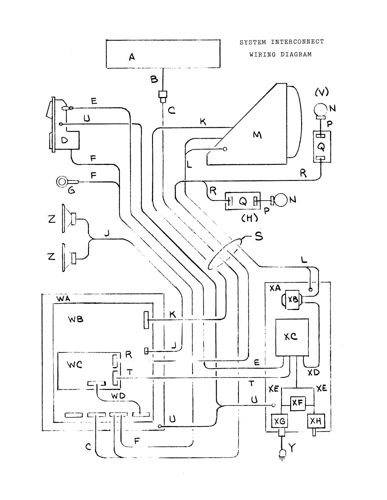
3 System Interconnect Wiring Diagram (with 47-49 references to drawing numbers following two pages)
4 Danger Zone Cinemat Main Logic Printed 50 Circuit Assembly Drawing (Component Side)
5 Danger Zone Cinemat System Dual Shaft 51 Encoder interface Printed Circuit Assembly Drawing
6 Mounting Diagram Dual Shaft Encoder 52 Board
PAGE 5
A. WARRANTY
Seller warrants that its printed circuit boards, monitor and power supply, when furnished with the product and parts thereof are free from defects in material and workmanship under normal use and service for a period of ninety (90) days from date of shipment. Seller's warranty of above parts is subject to the normal use and service of its product. None of the seller's other products or parts thereof are warranted.
If the products described in this manual fail to conform to this warranty, seller's sole liability shall be, as mutually agreed, to replace or repair such products which are returned to seller during said warranty period provided.
CONDITIONS:
a. Seller must be promptly notified in writing upon discovery by buyer that said products are defective. b. Products must be returned prepaid to seller plant. c. Seller's examination of said products discloses to seller's satisfaction that such alleged defects existed and were not caused by accident, misuse, neglect, alteration, improper repair, installation or improper testing.
Seller is not responsible for bent pins on ICs not installed by seller's employees. In no event shall seller be liable for loss of profits, loss of use, incidental or consequential damages.
Except for this express warranty, seller disclaims all other warranties, expressed or implied, including the implied warranties of merchantability and fitness for a particular purpose, and all other obligations or liabilities on seller's behalf, and it neither assumes nor authorizes any other person to assume for seller any other liabilities in connection with the sale of products manufactured by seller.
NOTICE REGARDING THE USE OF NON-SELLER REPLACEMENT PARTS:
Seller recommends the use of only seller's parts when replacing any malfunctioning component or assembly in the seller's system. For safety and reliability, seller does not recommend or authorize any substitute parts or modifications of seller's equipment. Such alterations may adversely affect game play, cause serious injury, and void your warranty. Unauthorized parts, modifications and non-seller's game conversion kits may also void FCC compliance.
To obtain repair, contact seller at 619-562-7000 between 8 AM and 5 PM Pacific Standard Time to obtain an RMA return authorization number. Affix this number to the outside of the shipping container when returning goods. Return to the above address,
PAGE 6
B. HINTS FOR SUCCESSFUL GAME OPERATION
PAGE 7
B.
HINTS FOR SUCCESSFUL GAME OPERATION
Take some advice from the game masters. Successful game operation can be simple if you take a minute and read the following hints. It is worth it's weight in aspirin!
1. RUN DIAGNOSTICS
If you are having trouble with a certain feature on your game use the diagnostic feature. Five minutes of diagnostics may save an hour of frustration wondering why a feature does not work. Our software department is the best in the business. They labored iong and hard to write diagnostics to thoroughly check out your game. Take the time to follow the diagnostics section and prove to yourself that the entire game is working properly.
Next, play the game a couple of times to verify that all is well.
MONITOR OUTPUTS
For future reference the outputs from our system to the monitor are red, green and blue with negative horizontal and negative vertical sync,
HOW DO I TURN UP THE SOUND ?
Volume adjustment is easy. Refer to figure 4 and locate VR1 (on main circuit board). Now look at the main board (largest board). Clockwise rotation increases the volume.
PAGE 8
C. BOOKKEEPING/DIAGNOSTIC FUNCTIONS
PAGE 9
C. BOOKKEEPING / DIAGNOSTIC FUNCTIONS
- INVOKING DIAGNOSTICS
With the game running in the attract mode follow these steps:
a. Press and hold the one-player start button while pressing and releasing the service button (found inside the coin door mounted to the top of the coin box).
b. Release the one-player start button.
Cc. The game screen should now appear. Instructions for selecting and entering the listed functions are displayed at the top of the screen with the five selectable options below them. The game's software version number is shown in the lower left-hand corner of the screen.
- SELECTING THE DESIRED FUNCTION
The one-player start button selects the desired function, The function has been selected when the display color for that particular function changes. Pressing the two-player start button enters the selected function. Selecting the RESET THE GAME function returns the game to normal operation.
An example of the display is as follows:
MAIN MENU
SELECT FUNCTION WITH ONE PLAYER START BUTTON ENTER FUNCTION WITH TWO PLAYER START BUTTON
BOOKKEEPING DIAGNOSTICS GAME SET-UP HALL OF FAME GAME DURATION STATISTICS
RESTART GAME CANCEL CHANGES AND RESTART GAME
S/N: XXXXXXXX
PAGE 10
BOOKKEEPING
The bookkeeping screen is displayed when that option is selected and entered from the main menu. Five lifetime counters are shown. These counters are set to zero at the factory and are not resetable by the operator. These counters are:
COINS DROPPED MECH 1- This counter shows the total number of coins that have dropped through the LEFT coin mech.
COINS DROPPED MECH 2- This counter shows the amount of coins that have dropped through the RIGHT coin mech.
TOTAL COINS DROPPED- This is the total number of coins dropped through BOTH mechs.
SERVICE BUTTON PRESSED- The number. of times that the service button has been pressed. Pressing the service button to enter the bookkeeping/diagnostic section does not affect this counter.
TOTAL CREDITS GIVEN- The total number of credits the game has given in it's lifetime is shown on this counter. (See the game set-up section of this manual for information on setting the number of coins per credit).
a. PERIOD AND DOLLAR COUNTERS
Three resetable counters, located to the right of the lifetime counters are provided to aid the operator in tracking the games' cash intake over a period of time. These counters are:
- coins dropped
- dollars collected
As in the main menu, these options are selected by pressing the one-player start button and entered by pressing the two-player start button. To reset the period and dollar counters for either coin mech, press the one-player until the message "RESET COIN MECH 1 (or
- DOLLARS COLLECTED" changes color. Then press the twoplayer start button.
b. SETTING COINS/TOKENS PER DOLLAR
To calculate dollars ollected, the bookkeeping system needs to know how many coins/tokens are required to make a dollar. Normally, this number would be 4 for quarter operation, If you operate a location where for example , 6 tokens equal one dollar, then the dollar multiplier should be changed to 6 so that the dollars collected counters will reflect accurately what the game has earned,
PAGE 11
To change the coin "multiplier," use the one-player start button to highlight the COINS PER DOLLAR message for the desired coin mech then use the two-player start button to change the multiplier.
EXAMPLE OF SETTING TOKENS PER DOLLAR
An arcade giving 10 tokens per dollar should have the coins/tokens per dollar multiplier set as shown.
An example of the display is as follows:
10 COINS PER DOLLAR COIN MECH 1 10 COINS PER DOLLAR COIN MECH 2
BOOKKEEPING
SELECT FUNCTION WITH ONE PLAYER START BUTTON ENTER FUNCTION WITH TWO PLAYER START BUTTON
LIFETIME PERIOD COINS COINS/DOLLARS
| COINS DROPPED MECH 1 | 0 | 0 | $ 0.00 |
| COINS DROPPED MECH 2 | 0 | 0 | $ 0.00 |
| TOTAL COINS DROPPED | 0 | 0 | $ 0.00 |
SERVICE BUTTON PRESSED 0 TOTAL CREDITS GIVEN 0
RESET COIN MECH 1 DOLLARS COLLECTED RESET COIN MECH 2 DOLLARS COLLECTED
SET COINS/TOKENS PER DOLLAR= 4 COINS PER DOLLAR COIN MECH 1 4 COINS PER DOLLAR COIN MECH 2
RETURN TO MAIN MENU
PAGE 12
- DIAGNOSTICS
The diagnostic menu is displayed upon entering diagnostics from the main menu. The player can then select the desired function,
An example of the display is as follows:
DIAGNOSTICS
SELECT FUNCTION WITH ONE PLAYER START BUTTON ENTER FUNCTION WITH TWO PLAYER START BUTTON
BUTTONS AND CONTROL TEST PROCESSOR MEMORY TEST VIDEO ALIGNMENT SCREENS VIDEO MEMORY TEST SOUND TEST VIEW BACKGROUND SCREENS
RETURN TO MAIN MENU
a. BUTTONS AND CONTROLS TEST
This test allows the operator to check the game controls and switches, Pressing a button or activating a control causes the description of that button or control to change color on the video screen.
BUTTONS AND CONTROL TEST
PLEASE PRESS THE FOLLOWING BUTTONS=
PLAYER 1 START CLOSED PLAYER 2 START CLOSED MECH 1 COIN SWITCH MECH 2 COIN SWITCH SERVICE SWITCH
FIRE BUTTON MISSILE BUTTON
HORIZONTAL SCROLLING
VERTICAL SCROLLING
PRESS FIRE AND MISSILE AT THE SAME TIME TO CALIBRATE TURRET.
PRESS THE PLAYER 2 OR SERVICE BUTTON TWICE TO EXIT.
PAGE 13
PROCESSOR MEMORY TEST
The processor memory test checks all on-board RAM and PROM memory with the exception of the video memory. The messages TESTING MASTER ROM, TESTING MASTER RAM, TESTING COLOR RAM, TESTING SLAVE PROM, TESTING SLAVE RAM will each appear on the left side of the screen as each of those tests are performed. The result of each test (pass or fail) is displayed on right side of the screen next to the description of that test.
Two error messages may appear during slave memory test, these are COMMUNICATION ERROR and SLAVE NOT RESPONDING. IC's to be checked, in order of priority, are listed below:
COMMUNICATION ERROR - a. wUlg9 b. U21 ec. U45 d. vu60 e. U62 £. U64
SLAVE NOT RESPONDING - a. u10 b. U3 Cc. ul da. U2 e. U20,U18 £. U61,U63
In the case of a failure of a ROM or RAM, the location (U number) of the suspected part is shown on the screen.
The following is an example of the display indicating a U107 failure:
PROCESSOR MEMORY TEST
| TESTING MASTER ROM | MASTER ROM | BAD |
CHIP U107 SUSPECT
| TESTING MASTER RAM | MASTER RAM | GOOD |
| TESTING COLOR RAM | COLOR RAM | GOOD |
| TESTING SLAVE ROM | SLAVE ROM | GOOD |
| TESTING SLAVE RAM | SLAVE RAM | GOOD |
PRESS THE PLAYER TWO START OR SERVICE BUTTON TO EXIT
PAGE 14
ce VIDEO ALIGNMENT SCREENS
Three video alignment screens are provided to aid in adjusting the game's video monitor for maximum picture quality. Refer to the video monitor technical manual (not supplied) for technical information and adjustment instructions.
The first screen consists of a white crosshatch pattern. This should be used to adjust screen position, horizontal size, vertical size and focus. Pressing the player two start button advances the display to the next alignment screen.
The second alignment screen is used to adjust the red and green intensity. An eight level (0-7) color scale is shown for each red and green. The monitor should be adjusted so that level zero is black, and one through seven appear as seven distinct levels.
The third alignment screen shows a four level blue color scale. Adjust the blue intensity so that level zero is black and levels one through three show as three distinct levels of blue. Eight other colors are also displayed for reference, they are from 0-7: blue, green, red, cyan, magenta, yellow, gray and white.
d. VIDEO MEMORY TEST
The video memory test checks the foreground video memory. The test appears as a series of colored bars moving across the screen. After each pass (about 5 seconds), the results of the test will be displayed on the screen.
If the test was successful (all RAMs good), the message "VIDEO RAM CHECKS OK" will be displayed for about 1 second and the test will be repeated. Pressing the twoplayer start button anytime during the test will abort the test and return you to the diagnostic menu.
If the memory test fails, the message "VIDEO RAM TEST FAILED" will be displayed along with the location (U number) of the suspect RAM. In the event that the video error is unreadable, a series of tones will also indicate the suspect chip (see table below).
NUMBER OF AUDIBLE BEEPS SUSPECT ICs
2 U35 and U36 4 U33 and U34 6 u48 and U49 8 U46 and U47
PAGE 15
e. SOUND TEST
This allows the operator to cycle through all the different sounds in the game and verify that each sound is clear. This will cycle through to the end of the test one at a time.
SOUND TEST
SOUND TO HEAR EXIT SOUND TEST
PRESS PLAYER 1 TO SELECT SOUND. PRESS PLAYER 2 TO HEAR SOUND.
f. BACKGROUND AND SCROLLING
This test is set-up to view all of the background screens by using player 1 start to advance each screen or the entire background may be scanned by vertical and horizontal movement of the Turret.
BACKGROUND AND SCROLLING
NOW VIEWING PROMS U70 AND U92
PLAYER ONE ADVANCES PLAYER TWO EXITS TURRET VIEWS SCREENS
GAME SET-UP.
The game option set-up section allows the operator to change various game options. As explained in previous sections, the one player start button selects and highlights the desired function and the two player start button enters or executes the function.
a. COINS PER CREDIT / CREDITS PER COIN
The coinage of each mech may be set to require multiple coins for each credit or give multiple credits for each coin.
To change coinage, follow the example screens below: (All examples assume 1 coin=25 cents
For 25 cent play: 1 COIN FOR 1 CREDIT
PAGE 16
For 50 cent play: 2 COINS FOR 1 CREDIT
Two plays for 25 cents: 1 COIN FOR 2 CREDITS
EXTRA PLAY
An option is included to award an extra play for the insertion of multiple coins before the game is started.
For example; if the coinage is set as follows:
1 COIN FOR 1 CREDIT EXTRA PLAY FOR 2 CREDITS
Then the result will be, 1 coin will give 1 credit and 2 coins will give 3 credits. Each additional coin will add one credit.
ATTRACT MODE SOUND
This option when selected enables the game sounds during the attract mode,
An example of this is as follows:
GAME SET-UP
SELECT FUNCTION WITH ONE-PLAYER START BUTTON ENTER FUNCTION WITH TWO-PLAYER START BUTTON
COIN MECH 1 1 COIN FOR 1 CREDIT NO EXTRA PLAY
COIN MECH 2 1 COIN FOR 1 CREDIT NO EXTRA PLAY
TWO PLAYER INNING FOR 1 CREDIT NO ATTRACT MODE SOUND YES
RETURN TO MAIN MENU
PAGE 17
d. DIFFICULTY LEVEL
The difficulty level on the game is set by the operator. The levels range from one to eight with eight being the most difficult.
HALL OF FAME
This function allows the operator to erase the top player lists from the attract mode.
HALL OF FAME SELECT FUNCTION WITH THE ONE PLAYER START BUTTON ENTER FUNCTION WITH THE TWO PLAYER START BUTTON
ERASE HALL OF FAME ON EXIT. . . « « + « » « »NO
RETURN TO MAIN MENU
GAME DURATION STATISTICS
Graphs are provided which indicate the number of one and two player games. Average play time is also displayed. These graphs may be reset by selecting the reset options located at the bottom of the screen.
GAME DURATION STATISTICS
SELECT FUNCTION WITH ONE PLAYER START BUTTON ENTER FUNCTION WITH TWO PLAYER START BUTTON
ONE PLAYER GAME TIME AVERAGE TIME: 0:00 0:00~1:30 0 1:31-2:00 0 2:01-2:30 0 2:31-3:00 0
PAGE 18
TWO PLAYER GAME TIME AVERAGE TIME= 0:00 0=00-3=00 eo000000000
RESET PLAYER 1 STATISTICS RESET PLAYER 2 STATISTICS
RETURN TO MAIN MENU
SYSTEM TROUBLESHOOTING GUIDE
The entire Cinemat game system can be broken down into major groups. A brief guide to troubleshooting each section follows:
- INPUT/OUTPUT FUNCTIONS:
a. MONITOR
i. No raster (i.e. black screen)
a. Check AC supply to monitor. If there is no power at the monitor, trace the wiring back to the isolation transformer and/or verify that power is reaching the transformer.
b. Check monitor fuses.
- Display scrolls (apparent syncronization problem).
a. Check monitor alignment adjustments,
b. Check RGB and syncronization signals on PCB connector and trace through to the monitor.
- Black screen
a. Check for +5.0 VDC at circuit boards.
b. Check connectors are securely seated and in the proper position.
PAGE 19
a) White or checkerboard screen.
a. Check for +5.0 VDC on P4 - 3 through 7. If any of these signals are low, replace U114 (74LS08). If this fails, replace U119 (74LS257).
be Check the clock signal on the master Z80 (U99-6), BASEBALL, THE SEASON II I/O and Memory Expansion Board (U13), REDLINE RACER Sound Board (U14).
ce. Check reset on the Z80 (U99-26). This
signal should normally be high and go low when the reset button is pressed.
White or red vertical lines close together on entire screen or half of screen.
a. Check video RAMs U33 through U36 and U46 through U49. Refer to sheet 11 and 18 on schematic.
Vertical lines on playing field (background).
ae Check signals on U81 through U83 (74L8166's).
be Regarding other background problems, check the position of JP2 Jumpers, swap U56, (74LS461) with U60, see if problem disappears.
White vertical bars, usually on half of screen sometimes with an audio buzz.
a. Caused by excessive temperature. Swap U45 with U23 and/or U60 with U22 (74LS461's).
Intermittent flashing video or color changes.
a. Check for +5.0 VDC at circuit boards. TP1 and TP2 (+5 VDC)
Picture freezes.
a. Check for +5.0 VDC at circuit boards. TP1 and TP2 (+5 VDC)
b. Check 2Z80s (U1 and U99). They should be Zilog Mostek devices with a "B" suffix (6 MHz). If not call for replacement.
c. Check for damaged sockets on master EPROMs and master CPU.
PAGE 20
- Drifting pattern (any color).
a. Check connector and signals on Pl.
be Sign of synchronization problems. Check DCLK.
c. Check U40 (RGSO9), U42 (RGSO7), and U43 (RGSO8) .
b. BUTTONS JOYSTICKS AND COIN COUNTERS.
- A careful visual inspection of the buttons, harnesses and connectors is advised.
a. Inspect harness.crimps.
be. Check for broken wires.
¢. Check for broken solder joints at the termination point.
2. ae signals through back to the input IC on the
- ELECTRONICS
a. MAIN BOARD ELECTRONICS.
2 Problems can sometimes be traced to a bad CPU or crystal. Check the master and slave CPU's and their associated components.
- Check EPROMs for background and foreground display and the associated video timing logic.
w . Check power at the ICs.
b. ADD ON BOARD(S) THAT CONTROL GAME SPECIFIC FUNCTIONS.
- Again, check for functions specific to the board.
- Check all ICs for proper socket installation,
- Check power at the ICs,
- GENERAL KNOWLEDGE
A. Proper voltage input jumpering on the board is critical! Follow the instructions on this carefully. A symptom of improper jumpering is an audio buzz or no audio, Check for 12.0 to 15.0 VDC at U122-5 (audio amp). Refer to Power Supply Modification section of manual. NOTE: If your speaker is not connected, you will not
PAGE 21
hear any sound! Seriously, try adjusting the audio volume control pot (VP1). See section B-3 above on adjusting the volume.
GAME POWERS UP WITH GARBAGE ON THE SCREEN - NO BUTTONS FUNCTION - AUDIO MAY BUZZ
- Remove P4 and P5 and reset system (push button on main board). If picture appears, the problem may be a stuck coin switch, button or bad harness or ground connection.
- Visually inspect connector crimps and wire colors.
- Check for + 5.0 VDC at board.
A WORD ABOUT COIN COUNTERS:
Do not use mechanical coin counters in any kit or dedicated game. These devices produce an inductive "kick" that will damage components on the circuit board(s). Problems caused by this are checkerboard video. A quick check to see if this is your problem is look at the "NMI not" signal on both Z80s (pin 17). If a low output is observed, try replacing U114 (74LS08) or if needed, U119 (74LS157).
The bookkeeping on our games is very accurate and includes number of coins dropped and dollars earned.
If you must install a coin counter, the next page shows a simple hookup using diode protection.
PAGE 22
COIN COUNTER SURGE PROTECTION CIRCUIT
- IF YOU MUST INSTALL A COIN COUNTER
COIN SWITCH
COIN COUNTER
Phd OR Ph-T +5V
DIODE MAY BE 1N4001 THROUGH 1N4003
PACE 23
/npRon2 (2) Se enPRON C2) Pe enPROM4 (21 Pr enPROMS £2) R 8-21 tsivntnc 2] 33/NURL 3. 19. ee/COLUR (12) C4) HCOL ra 13. oe /MPLDL 63,10) $ AZ ymPLDH 618) SH HS npcLK £182 ka [iS vnkana £29 3 ia enrant (22 S 43 /COLSEL C121 ae vei uss [22 vr 5 ts2 ry enpai3c2
| Te hrar | ase | “ee | |
| ci | Alz | ee mAL2 | |
| [ ae | ain ft | t | Pena |
| 28 feo | Are [32 | Pao | |
| +s | as [33 | Pnags |
ag 133 eras
| 173/02 | a7 ba | aed |
| cisiuarr——____] | as [28 | Pon as |
| C427nNNI. | as 34 | PH HAS |
as an a3 [33 a2 [82 ai [St 60 [22 -———_—_ +s Ls245 pb? [43 Stas es [t4 25>
| be [22 | HE | Sas pa fis ee |
os {8 a3 P3 Senos | 2.3.43
| te uaie | D4 | = a2 82 1 PD 18.427 |
| C1SKUSYNOD | 3 [& | + AL BL Tr wenps [613,147 |
| D2 [i | eRe Be | ene | cia |
bi BS Star a7
| 23 fee | Zhe Be | ot) |
INTACK tore
| zol2t | Ls2e4 | P18 use0 |
| um [22 | S§fias rvalts | Pas t2.3.9.121 |
| fri] ee | S|iae vali | Pnazt2.3.8.16) 7 |
| ToREG {22 | tS 144 v4 = | Prnar [2.3.9.16) |
| fir [22 | gar avipt | $y nae (2.3.9. 18) |
| 23teusace = wary fie | 13] 2a2 2v2(2 | toned tab es |
| ‘RFSH LS. | 12) 244 2v413 | fe enuR (2.33 |
CEE 18] 2a3 2va[S
| ue Zar 2yi/8 | P/nIOREO (22 | CINEMATRONICS |
fos CINEMAT SYSTEM LEER} TITLE sl vw MASTER CPU SYRE | CODE [NOREER FED B 81~-12176-12 a ATE S=3E=8s TEHEET—T-Ge 1S
| @ | T | 7 | T | € | © | T | 4 | z | 2 | fi |
caanpars.
Prarie Zi larg
42 snpROn4:
cnpRone 7MPRONL meron 7MPRONS. T MASTER CPU PROM/RAN
[pare $=3e-68 Tenet sor a8) 2 + CIMEMATRONICS CINEMAT SYSTEM
8 2
| 6 | 5 | 4 | \ | 2 | 1 |
usisa issra
| vaiwe tar | - | 2 2h2 | unis 12.173 |
| yeint £43 | sD 6a | bia t120199 | |
| Sein2 tal | 33 sa (8 | Sons i217 | |
| eiGID C182 | ep ea [Hs | SpeuDi2 (12.173 |
2D 0 2a Te UII £12.17)
| INPUT PORTS | ib lab | cups) tiga | |
| ‘DUTPUT PORTS | bat | : | |
| cr] nas, | 7 | ay ea fas | a-UDS 12.172 |
neon €43 7OGTA C18) YER
7ostD 183 D3KKL 133 usa74 DaKKh C13
| ezkKH £132 | _ | er? 012.179 |
| ome 3 | 1 | ee |
Suns tizsin
| (BKGND SCREEN | tt | DS 12,473 |
PLACEMENT) pups. tz) une 13.173 fount e219)
| (oo om | Lt | pane ESE SetS] |
- /MPCSEL (TO FOREGND VIDEO RAM)
> 3508
| i | 3 | @MUHR £92 |
nes-02 t12 snroree 1 12 /nRD 2
| (13 ore | } | 3 | 19 |
| 120 naz | ms | 18 | |
| ti] nas | 5 | az erent 92 | |
| {13 nas | § | 13 | |
| 120 maz | + | 2 | 1s |
| t12 mar | + | s | 18 |
| 112 nae | 3 | re |
peenuen 11
- vnpLbt Tyg 2 CINEHATRONICS a1 mp7 —__I CINEMAT SYSTEM tne —_= a1) mDS TITLE oa ns MASTER VIDEO DATA LATCHES
| i) fe | STE TEOSE | ROREER | FET |
cid mpi 81-12 a
| cid MDe. | 7 | bidiiiiaad | is |
BATE S$-25-e5 [SHEET 3 OF is
| 8 | * | 7 | |||
| 6 | S | 4 | 2 | T | 7 |
This page reads as a drawing: its text was drawn rather than typeset, and comes out in fragments. See the original scan.
-7SPROM@ C62 ‘7SPROML [6] —P-/sPRON2 £6} 1 /SPRONS 6) 7SPRON4 C6] = re) RGS-03
t61 ¢92 pt
ZULINE £73 ‘SBANK £73. 28RH (33 ‘7SPLDH C102 r @SPLDL (7.103 ‘“SPCLK (103 Pm SRAN 681 ‘eSRAML C63 12 scLK f—Pspais (62
[4 /SRESET Pe sai2 61 ¢ wersalt 6] ~ sais céa
- /StW’ —Ssas te} tel 42 7SNMI- tea (6.2) 6.73 esas cée.7)
t6.7.103 te.7,1a3 t6.7,109 |r 6.7.10 te.7-103 t6.7.103 (6.7. 1@3 t6.7.1@3
mm meee % r ‘<
| ores [Z2 | $102 1v2}ts | + | Sal (6.7.92 |
| aT | Zjiar svipts | tf | saa (6.7.93 |
234nosacR = watT 8 1S} 203 2va|_§ P/SRD 6.73
| Reeaes | tis] 284 2¥4--$ 4 | ce 0671 | |
| ut | ti] 3a; | 3 | - |
t 3 21 PH /STOREQ C72 CINEMATRONICS CINEHAT SYSTEM a
THE vv SLAVE CPU
‘¢SHALT (47 ‘SIZE [CODE [NUMBER REV B @1-12178-12 A DATE 5-36-05, [sheer SOF TE ry 7 6 T S 2 3 2 T 1
£82 spai3——_
¢s3 vspRon4
82 SADD: s2 +8) ts) 7SR0 53 7suR—] 5] /spRons: (s3 /spRonE—y (S32 7srane ts) 7sRani ts) SDA’
61 sPRone 62 /spRom
- ¢spRON2 (61 sPRona
This page reads as a drawing: its text was drawn rather than typeset, and comes out in fragments. See the original scan.
| 8 | | | 2 | ‘ | | | § | 4 | i | 3 | L | 2 | 1 |
+s 874 +s sz 2 1ef= aq |svas (182 tae ° ise t-154 =
| vas (103 | Hi | se | 745 | ' |
| D | vas | ar} | Le | cneatx |
| VAs 102 | & | BEKrteg) |
vez (183 we val (103
28-07 SYNC £12) cap pen a2 a (2B, 2.
c c
P-CUBLANK (42
92 /DCLI C132 Bxe. = 0132 xt 133 x2
s. HCNT £132
2 ‘ 2
SRL (13.163
vais LVALB vai2 7.10.14) £7.10.143 €7.10.143 7.10.14) (1.7.10, 14: 07.10.142 07.10.1423 €7.10.142
sbkgnd pixel cnt rys 7.8 = RAM addr cntrs vipeo Appa sur-ur
CINEMATRONICS: CINEMAT SYSTEM 7
Hacc {EEE S=2s-e8 [sub eo is
| ‘ | z | ‘ | 5 | i | 4 | 3 | | | 2 | t | : |
+5 s74 venticar
vCash C412
7CASL C112 £163 Rae $02 Mon tzontan
| sea | 1128 | [oe et eras ea |
Ss f § 2 ES ta. usa i" PpcLK 8.12.162 —PeDCLK (8.161
a iste
(73 Na —e,
| 13 enRH | c7a Ne | rine eli | |
| : | isi2s | i | fut C113 |
| tea ont | sh>2 | —_ o |
us2 at 1 t3) se is136 pr rE 8,10) $e4 C72 /sTL 12 An 13 12 Us2 m3 610.18)
| t9) 7P1 | tes | vine |
(52 /sRH
18175 4 for so} _2
| 22 nas | + | 2 | 43 | PHPRSEL (103 |
| {12 maz | i3]p3 bho | 7 | ‘MPCSEL £3.18) | |
| 13 nay | eos sorte | a2 | PyHINC | C19 | |
| 12 nae | seris. | = | “MDS 3.92 |
a2 /nuue———T tere EP a
| C93 an | zoe | 43 | ope (123 |
u39 u26 f°} pi 0178.9.10.123
ReS=14
1si7s 2 12% 3 a0} 12
| rsa saa | 2422 aalit | 2 | 43 | “P-/SPRSEL £10) | CINEHATRONI CS | |
| tsi saz——- 02 BPS | é | 4s | P/SPCSEL (7.102 | CINEMAT SYSTEH | ||
| cs) sat | ily, Fabs | € | Ts | P/SINC | £5] | ||
| ts3 sae | iar | aE | ie | 7SDS £7, 82 | TaSee. | |
| 2 | TEs 1 | {se | 14 | VIDEO RAM R/H TIMING | ||
| £73 esuuR | ton Mee | a | i | |||
| £91 ¢sps———-4 | Pome) | t | °F | P2123 | SIZE [CODE [NUMBER | REO |
| — Lure P | y27 ees 012) | B | 81-12178-12 | ry |
Lo Tare S255 [SHEET SOF
| 3 | T | 7 | T | $ | T | = | T | = | 3 | 2 | 7 |
| 2 | 2 | | | 6 _1 | s | 4 tL a | 2 | 4 |
vapp
| presse | pistes | tana | ||
| 2 | 22__rat | 5 | 22 Rat | |
| > | z | 21 Raz | = | 21 Ra: |
| 28 Ras | $02 = | 20 Ras | ||
| is Ras | $D3 | is Raa | ||
| 1s kas | Spa? | is Ra | ||
| i? Rae | [se | [17 Rae 4 | ||
| is Rae | sae | [is eae 4 | Rae ¢9.219 | ||
| 12 MDA’ | is | cs) spataef_ 8? 18] | [is |
| [ 14
| “|cox enresee | cas ssreser | I | 3 |
+s
Z4LS461 3 RP2 c 113 /meenk 83 /seciK. aes i
+ —]
I
- /npLDH 82 /sPLDH.
| ca 7MPLDL | Z | (53 /SPLDL. |
13 14
| £93 /nPRSEL | vas | c91 /spRSEL |
S257 csi 2Jia ivy}4 Rae te) UA4. tea var4—_3_ lip lie eer | (81 vatt. 82 ‘VAL 14} 4a ay cel vas
| (82 vas. | “a [> ee | | 81 vat: |
te) VA2. S\2a 2v ca] vAG
| | | (82 vas. | 23 [> eas | | 83 vat |
- UAB. Jilsa ay ce] VA? te) vate 19} ap 93 ven te set (91 7b doe 5,
CINEMATRONI CS a CINEMAT SYSTEM TITLE UIDEO MEMORY ADDRESS MUX
81-12178-12
| 8 | 7 | 6 | 5 | T | ey | 3 |
| 8 | ii | a | st | 4 | | | 3 | i | 2 | t |
aaienis aai6-i5,
| a2 | $fRS | vaz | Se |
| Rei | 4 | 6 FP oy | x |
¢93 rune 4 £92 un 33 33 RATION, RAT et,
| a | H | Race [2 |
| 7 | Ras 7s | Ras 7 fs |
fase hs Rees tS Ras tits pq |_2 uns RAS ths pa [15 uve Razszt, pg [Tz-ubz Razz, >7 [suns Raiiste;, py supt Rarist? 3S tre-vprel Reeiaf, 3) (7s-upe Reeisks ba [-eupit Tae was aaignis 4416-15 s s 3 tee 4 * i RAT Oe RAT 1 ae ee Ras ee Ras? ee RAS? Ire eae hs naae tS,
| c | RAS tiles pq |_2 uns | RAS ATES pa [15 ube |
| faa | Raz izle, pg [Te-upz | Razizis ps [suns |
Raise; py [Supt Rais}? © 3! rrupret watafa, 33 fisupe Ree iss bap eusi r92
| a7 | as | pata |
(173
t93
| 102 vaDD | 446-15 | 4416-15 | ||
| u32 | Se | use | ia | 7c |
Re. Re
| 2 | 93 cunt —2,RPL 14 | 4 | 91 suna__2 22h 10 | 4 |
| 33 | i | 33 | 1 |
RAT, RAT, mace tie Rage (2 Ras? he Ras 7s aaa hs Raa e {5 Ras ties pg {as oa RAS ibs pp [4s vos7, Raz iz, 3? [-s-une Razizes © 32 (supra Raita; 34 {i7-upe RAIigia; ps [Er-upia
| - | Reatah, 33 peu | aeteys 33 evpre |
033 Tas aai6-15 4416-15 s 5 Totes is 4 2
| r | r | CINEMATRONICS | |
| A | RATS | RATA, | CINENMAT SYSTEM |
Ras 6 Rage
| ees he | See be | Frere |
| Rae ts | Bees | VIDEO MEMORY |
RAS tT Ins pg {Us ude RAS TS — pz [as vD12, Razaetss = 3? Sup razizis 2? s-unisp [sree] cove [RUREER FEY
| Rarist; 3) yupe | arise; patie |p | 81-12170-12 | a |
Raetete, 23 ope Raoiaes — 23 euprs
| a | ers | DATE 5-78-05 | [eee i oF 7s | |||||
| 3 | T | — | $ | : | T | 3 | 2 | T |
This page reads as a drawing: its text was drawn rather than typeset, and comes out in fragments. See the original scan.
32 73Kx
c1y mp? ci] mp6 e120 mips C12 mp4: C12 mp3 e120 mp2 C12 ompt C12 pe 1g eBK2 (82
- KI C83
- Ke £82 i 2 1
7a1s461 tea sr ‘163 e183 1183 C183 1s) £183 C153 £183
CINEMATRONICS CINEMAT SYSTEM
FTTLE BACKGROUND HORIZONTAL ADDRESS
STZE CODE TRONBER cy B 1-12178-12 a DATE 5-75-68 a TFs 2 ri
This page reads as a drawing: its text was drawn rather than typeset, and comes out in fragments. See the original scan.
This page reads as a drawing: its text was drawn rather than typeset, and comes out in fragments. See the original scan.
| 8 | it | 2 | i | s | i | 4 | 3 | 2 | 4 |
| 27128 | Lsi6s | 1s187 | |||||||
| soho be | ont? | ZH 10 | Pe nsu2 123 |
aaiananianelicanne 3 rf f1] maz 2 13
| hs | id WaT | Bsu1 C122 |
4 ~
| sone | RTT | asve C123 |
ats 12 3 az 25 has uicor 24 lag ta ES 18
| 2 | a | 182 |
zee *19 ve
27. £123 P? usa
| teas | 27128 | sis |
| LCAs. | iehe oa}t | 2fa aw |
Sar 01 [12 Emr S202 [18 ate Zaa oa [1S mr Shag oa 3S. ile
| 5 | 17 | 1 |
| (42 ucor | ahs oehe | 12] § |
he oss ia] 5 25 hag 4} 1 24 a3 1 2ibate 35] su 23 taut +5—S-d CER 2 lai2 ara{26 2
| 92 /peLK | 23, | a2 |
27eeh n PP yo
(143 Buac she (141 Buat cm (143 Bua: She £153 cae mn (153 cat 2 f1s3 ca SPs e183 ca: ae C153 cae Sap? c151 ca 38 tas (153 cas 24 las 152 ca’ 2Ubare
| f14) cas | t | 23 4art |
143 cas Zaiz ars 27 CINEMATRONI CS: 1 Ver vos CINEMAT SYSTEM +s TLE BACKGROUND CHARACTER GENERATOR Voce crs 92 peLK WORBER ter rset @1-12178-12
| 8 | T | ? | 5 | 4 | 3 |
3.7112 unis tegta upis C3.7-313 UDI tacpdda UBL t3.7ein], UbiL taopenidUpy > tacpiia ups 3.70113 uDe t183_sapet tea vei
¢
3.70112 ype fecreti3 Ube targa ube 03,7-513 vup4—— 4 (3.7443 ype tarts up 03-7.922 vbr €3-7.517 upe.
- /LDCL. te) Fi
>
v0 tas fb cre Beata star “sour +8. i | iwaias fR51 cre 12k Rs 1N414s ti.i82 CINEMATRONICS FE cory CINEMAT SYSTEM a RESET qf sm bea ont THLE
ee DAC SOUND OUTPUT
SEE CORE [MORE aE B 81-12178-12
a e173 £12 e173 12 ua cn r143 cn C16) rae) BANKING: fae CONTROL a
192 7B, £172 7POR.
vorune
£32 c161D
(33 7osta.
108K 132 roster.
fa renk. 4
8 6 T Gi 4 NOT INSTALLED FITLe eeerF
CINEMATRONICS CINEMAT SYSTEM R47? 33PF eek
GI SOUND OUTPUT SPEAKER
DB
NOT INSTALLED
bh co
1uF
©
B
STZE | COE [NUMBER @1-12178-12
This page reads as a drawing: its text was drawn rather than typeset, and comes out in fragments. See the original scan.
8 7 L I ; \
Mc24e [ere] 32 rs i ja
3. 4 Ey
2als491 “
i ; ;
:
: : ps s
: i
ra Liep—"* Eat | +
Lf 7k HCT240-
c1:Ci4 = 10uF C2-S:Ce-18;C1S = O.1 uF
[SHEET 2 OF
rom Sune ENCODER GUADRATORE OUTFUF Lg14 Fo ReaD crncurT
+s +s
opticaL INDEX Rand
THE LELAND CORPORATION
TILE SHAFT ENCODER DRIVER
STEE [CODE | NUNBER REU B 81-16200-81 B
PATE__6-8-87 SHEET] OF i 6 5 —T 4 Ey 2 T 1
id
sv a “Old
T NOILOANNOD YaMOd 3G/OW POWER CORD
GND +12V HOT 115 VAC
E.M.I. FILTER GND BLACK
oan y INTERLOCK
SWITCH 1 +5V
BROWN CONTROL PANEL 4 — N HOT
FLUORESCENT AC GND AC
LIGHT FUSE
(| WHITE GREEN |
ORANGE BROWN
BROWN
BROWN RED
GROUND BRAID ORANGE 10 >» LI Buack | 5 |_| ietack | | [| BLACK |_| BLACK | , | | au Rep | > Pep] ? YELLOW
YELLOW
a BLACK ra (_} _]
COIN DOOR LIGHTS
ISOLATION TRANSFORMER
PIN 10 PIN 1 Bw ° elelels ala lag ALR BPN WENA © © GROUND BRAID D
NEUTRAL | A
ORANGE Be °
BLACK PNWARU DA OO
A.POWER SUPPLY +5V @ 7A -5V @ 1A +12v @ 1A
B.I/O MEMORY EXPANSION BOARD
C.MAIN LOGIC BOARD
D.cIRCUIT PANEL PLATE
OUR PIN-OUT IS OPPOSITE OF THE PIN-OUT PRINTED ON THE CONNECTOF I.E. PIN 1 IS PIN 10 FOR A 10 PIN CONNECTOR
ONE PLAYER | PLAYER
Jour wn -
ov’ Om PIN 1 y Pit § ooobooooon GUN P4, PS RAR) L
SYSTEM PIN-OUT OPPOSITE OF PIN-OUT . . MOLDED ON CONTROL PANEL WIRING DIAGRAM HARNESS CONNECTOR
This page is a drawing, shown as the original scan.
SYSTEM INTERCONNECT DIAGRAM
CONTROL PANEL ASSEMBLY 38-30025-01
CONTROL PANEL HARNESS 87-18011-01
CONTROL PANEL INTERFACE HARNESS
COIN DOOR ASSEMBLY WITHOUT VAULT 19-30025-01
SHORTENED COIN VAULT 20-30010-01
COIN DOOR LIGHT HARNESS 87-18001-01
COIN/SERVICE HARNESS 87-14052-01
SERVICE SWITCH
SHORT RED BUTTON 37-11192-02
LEAF SWITCH WITH BRACKET FOR SHORT BUTTON 37-11373-01
SERVICE SWITCH METAL BRACKET 20-13135-01
(H) HORIZONTAL
J. SPEAKER HARNESS 87-18007-01
VIDEO HARNESS
MONITOR POWER/ GROUND HARNESS
MONITOR 39-10819-01 FOR N,P AND Q:
N.
U. (H) IS HORIZONTAL (Vv) IS VERTICLE
SHAFT ENCODER 50-11575-01
SHORT SHAFT ENCODER HARNESS WITH ECGE CARD CONNECTOR 87-18009-01
SHAFT ENCODER DRIVER PRINTED CIRCUIT ASSEMBLY 81-16200-01
SHAFT ENCODER INTERFACE HARNESS
MAIN HARNESS (MADE UP OF C,K,L,R AND WD) 87-18005-01
D.C.POWER HARNESS 87-16031
GROUND BRAID 87-16031-01
(V) VERTICLE
Y. A.C.POWER CORD 87-12143-01
T7-INCH SPEAKER 71-10834-01
4-INCH SPEAKER 71-10900-01
6x9-INCH SPEAKER GRILL 20-12398-01
25-01
v1
2h-01 i lOIZ
! vi
bo
FIG. 5
PAGE 51 U13
u12
& Loe Jt
| :
| ;
MOUNTING D.AGRAM, DUAL SHAFT ENCODER BOARD
©omm
®yymomm 6432 xX 1 1/2 PAN HEAD PHILLIPS SCREW ONE INCH NYLON SPACER