Asteroids DP-143-5th-01A
Asteroids (rev 4) (Atari, 1979) · Drawing Package · 1 pages · original scan
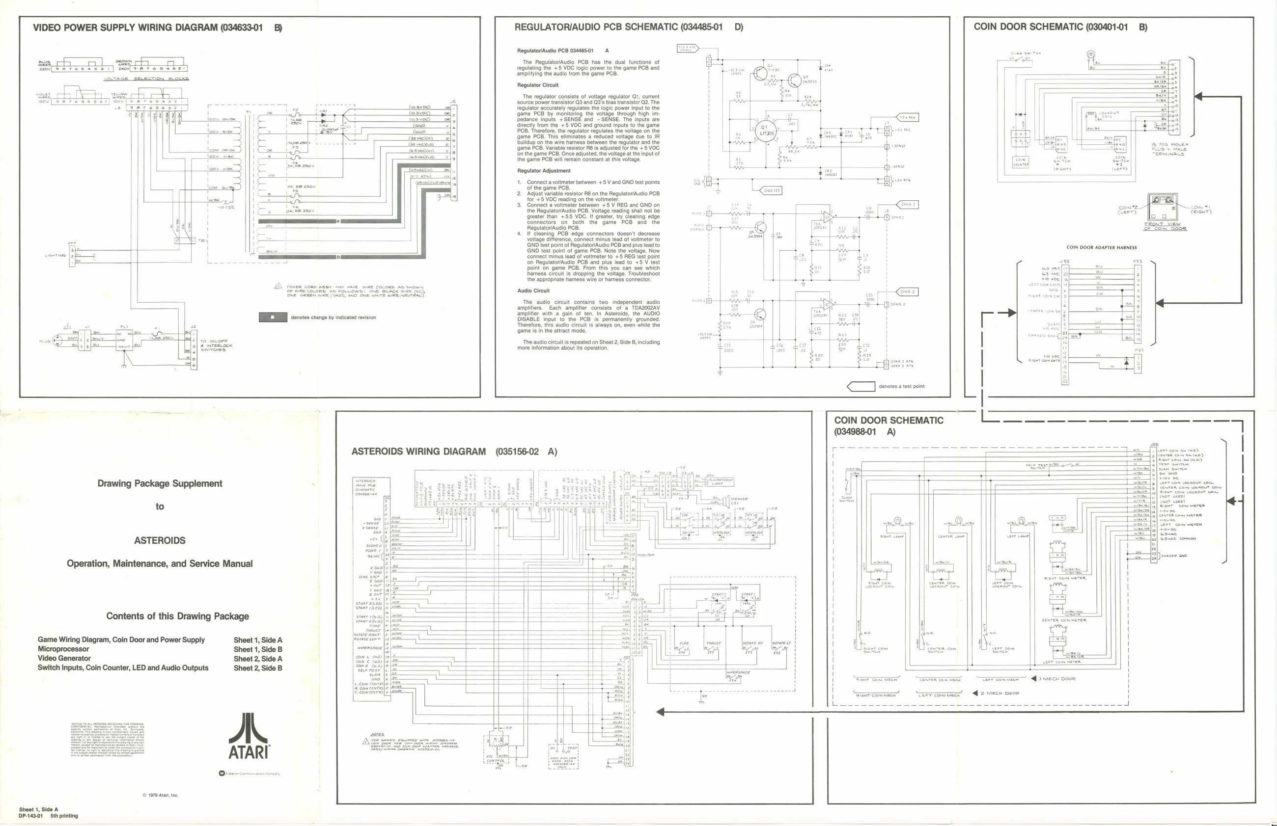
VIDEO POWER SUPPLY WIRING DIAGRAM (034633-01_B) REGULATORIAUDIO PCB SCHEMATIC (034485-01 D) COIN DOOR SCHEMATIC (030401-01 __B)
Regulator/Audio PCB 09448501 A
The RegulatorlAudio PCB has the dual functions of regulating the +5 VDC logic power to the game PCB and amplitying the audio from the game PCB.
Rogulator Circuit
The regulator consists of voltage regulator Qt, current
‘source power transistor QS and Q3's bias transistor Q2. The
regulator accurately regulates the logic power input to the ‘game PCB by monitoring the voltage through high iminputs +SENSE and —SENSE. The Inputs aro ditectly from the +5 VDC and ground inputs to the game PCB. Therefore, the regulator regulates the voltage on the le PCB, Tis eliminates a reduced votage ue to IR bulup on tne wie harass between the regu and the © PCB. Variable resistor Po is adjusted forthe +5 OG nthe game PCB, Once adjusted, the voltage atthe Input of the game PCB will remain constant at this voltage.
Regulator Adjustment |. Connect a voltmeter between +5 V and GND test points ‘of the game PCB,
2. Adjust variable resistor RB on the RegulatoriAudio PCB
for +5 VDC reading on the voltmeter.
- Connect a voltmeter between +5 V REG and GND on the Regulator/Audio PCB. Voltage reading shall not be greater than +5. VDC. If greater, try cleaning edge Connectors on both the game PCB and the Regulator/Audio PCB. Hf cleaning PCB edge connectors doesn't decrease voltage difference, connect minus lead of voltmeter to GND test point of Regulator/Audio PCB and plus lead to GND test point of game PCB. Note the voltage. Now Connect minus lead of voltmeter to +5 REG test point fon Regulator/Audio PCB and plus lead to +5 V test point on game PCB. From this you can see which harness circuit is dropping the voltage. Troubleshoot the appropriate hamess wire or hamess connector. TaswseKa 15 fos Movex
comme com +) S| eeicier
SSSA ots: ‘Audio Cireult
The audio cit it_contains two Independent audio, fa TOA2002AV DE ote nce neste ion yerefore, this audio circut is always on, even while the {game isin the attract mode,
‘The audio circutis repeated on Sheet 2, Side B, including ‘more information about its operation.
ASTEROIDS WIRING DIAGRAM (035156-02 A) eee
Drawing Package Supplement -
to
ASTEROIDS
Operation, Maintenance, and Service Manual
Srear seo) Contents of this Drawing Package
Game Wiring Diagram, Coin Door and Power Supply Sheet 1, Side A (orere ten i\. ae. ; Microprocessor Sheet 1, Side B SL one gow Sig om Video Generator Sheet 2, Side A Cea ‘Switch Inputs, Coin Counter, LED and Audio Outputs: ‘Sheet 2, Side B
A, ATARI ETE = SRG wx <3 mec o00R war comme” “Teercommecr’ = @ 2 mech poor
© 1979 Ata, no.
Sheet 1, Side A P-143-01Sthprinting