Soccer DP-144-1st-01A
Atari Soccer (Atari, 1980) · Drawing Package · 1 pages · original scan
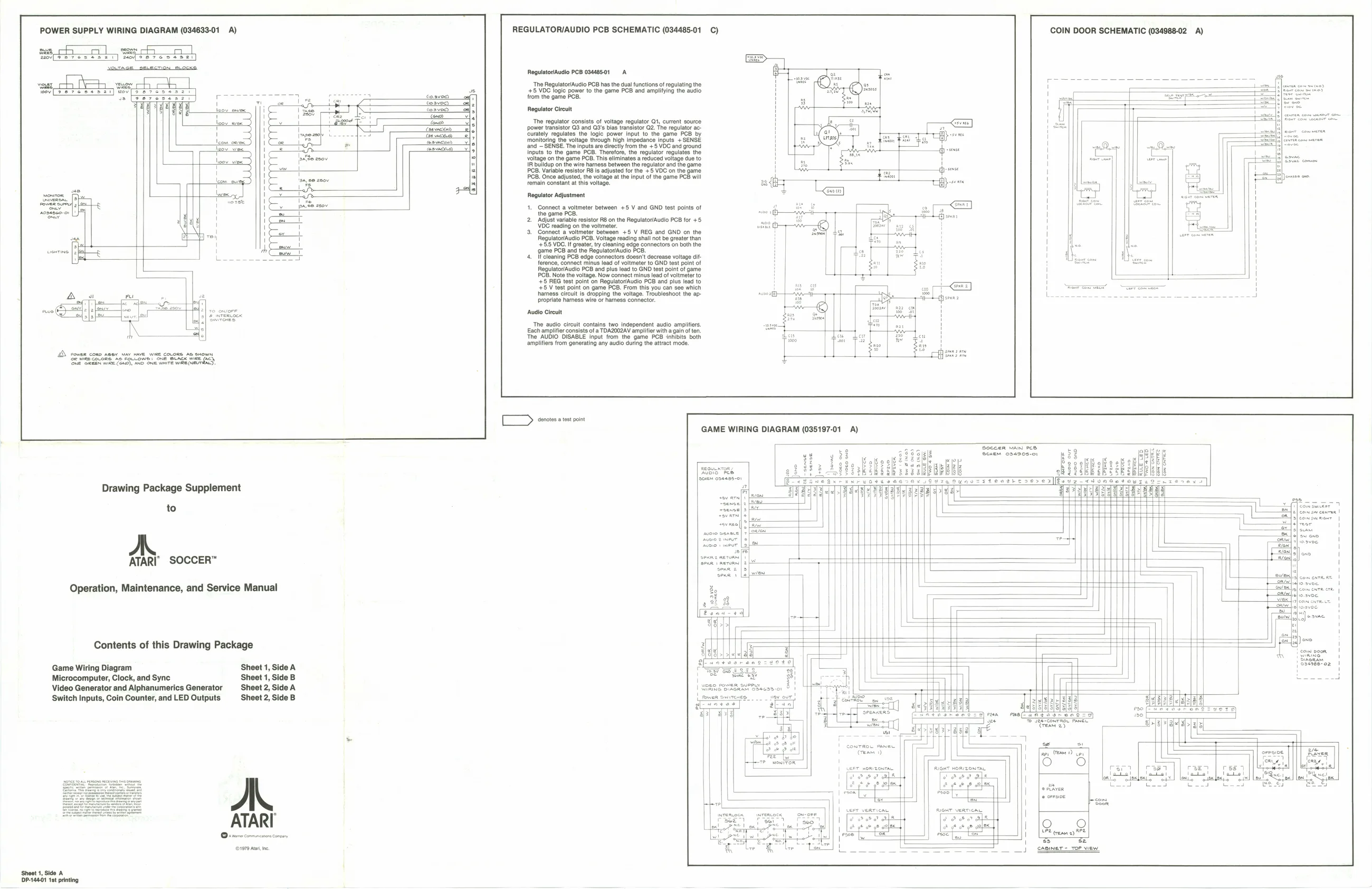
POWER SUPPLY WIRING DIAGRAM (034633-01 A) REGULATOR/AUDIO PCB SCHEMATIC (034485-01 COIN DOOR SCHEMATIC (034988-02 A)
serch
RegulatoriAudio PCB 03448501 A ‘The Regulator/Audio PCB has the dual functions of regulating the ZE,VOC oale power tothe game PCB and ampliyng the audio from the game PCE Rogulator Circuit 11 ieee ‘ove ere essai) wov[>
‘The regulator consists of voltage regulator Qt, current source power transistor Q3 and Q3's bias transistor Q2. The regulator ac- ‘curately regulates the logic power Input to the game PCB by monitoring the voltage through high impedance inputs + SENSE and = SENSE. The inputs af dec trom he + 8 VDC and ground Inputs to the game PCB. Therefore, the regulator regulates the OB, This: eliminates «reduced votage due to harness the regulator and the game Jatable resistor Ab is austed for tne + VOC on the game PCB. Once adjusted, the voltage at the input of the game PCB will remain constant at this voltage. Regulator Adjustment |. Connect a voltmeter between +5 V and GND test points of
+5 V REG and GND on the Regulato“Audio PCB. Voltage reading shal not be greater han +5.5 VDG. If greater, ty cleaning edge connectors on both the ‘game PCB and the Rlegulator/Audio PCB. If cleaning PCB edge connectors doesn't decrease voltage dit. nee, connect minus lead of voltmeter to GND test point of RegulatovAudio PCB and plus lead fo GND test pont of game the voltage. Now connect minus lead of voltmeter to ‘3 FG toat point on RopulatorAudlo POS and plus Tea to +5 V test point on game PCB. From this you can see which ‘ 7 harness circuit is dropping the voltage. Troubleshoot the ap- aa . so propriate hamess wire or harness connector. +h sren Audio Circuit The audio circuit contains two independent audio ampilfers. Each amplifier consists of a TDAZ0O2AV amplifier with a gain often, ‘The AUDIO DISABLE input from the game PCB inhibits both amplifiers from generating any audio during the attract mode. Sen covone. neta. Swe one sca we fey anges one fee CensS nas Sue ive WR
[TD orotate pit GAME WIRING DIAGRAM (035197-01 A)
‘Soccer WAN PC
on Drawing Package Supplement
to
ATARI SOCCER™
Operation, Maintenance, and Service Manual
Contents of this Drawing Package Game Wiring Diagram Sheet 1, Side A Microcomputer, Clock, and Sync Sheet 1, Side B Video Generator and Alphanumerics Generator Sheet 2, Side A Switch Inputs, Coin Counter, and LED Outputs Sheet 2, Side B moeanessr en a=®) eccanraee Pee i 7 (mam ae ea PO apy | areas wae ee
sever commumcanons Comeany se 7 PE reasn a) PE ~ 3 (©1979 Alte caper -