Primal Rage TM-395 1st Printing
Primal Rage (version 2.3, Jan 1995) (Atari Games, 1994) · Technical Manual · 68 pages · 53 sections · original scan
ay ~ Gunuidas, see-Wi.
This page carries no recoverable text. It is a drawing or a photograph. See the original scan.
Operator’s Manual
with Schematics
Patents are pending on several parts of the Primal Rage game.
INTRODUCTION Pxinal RAGE Orrrator's MANUAL
NOTICE
COPYRIGHT
Copyright © 1994 by Atari Games Corporation. All rights reserved. No part of this publication may be reproduced by any mechanical, photographic or electronic process, or in the form of a phonographic recording, nor may it be stored in a retrieval system, transmitted, or otherwise copied for public or private use, without permission from the publisher. The game play, all graphic designs, this technical manual, its accompanying schematic diagrams, and the display manual are protected by the U.S. Copyright Act of 1976. This Act provides for substantial penalties for violating federal copyright laws. Courts can impound infringing articles while legal action is pending. If infringers are convicted, courts can order destruction of the infringing articles. In addition, the Act provides for payment of statutory damages of up to $50,000 per infringing transaction in certain cases. Infringers may also have to pay costs and attorneys’ fees and face an imprisonment of up to five years as well as fines of up to $250,000 in the case of individuals and up to $500,000 in the case of corporations.
Atari Games Corporation will aggressively enforce its copyrights against infringers. We will use all legal means to immediately halt any manufacture, distribution, or operation of a copy of video games made by us. Anyone who purchases such copies risks forfeiting such a game. Published by: Atari Games Corporation 675 Sycamore Drive Milpitas, California 95035 Printed in the U.S.A, 7/94 Produced by the Atari Games Technical Publications Department. Design, Writing and Editing: Andrea Dencker Cover Illustration: Jason Leong NOTICE RE
PARTS NON-ATARI
You may void the game warranty (printed on the inside back cover of this manual) if you do any of the following: © Substitute non-Atari parts in the game.
- Modify or alter any circuits in the game by using kits or parts not supplied by Atari Games Corporation.
FCC COMPLIANCE
This equipment generates, uses, and can radiate radio frequency energy, and if not installed and used in accordance with the instruction manual, may cause interference to radio communications. It has been tested and found to comply with the limits for a Class A computing device pursuant to Subpart J of Part 15 of Federal Communications Commission (FCC) Rules, which are designed to provide reasonable protection against such interference when operated in a commercial environment Operation of this equipment in a residential area or modification to this equipment is likely to cause interference, in which case the user, at his own expense, will be required to take whatever measures may be required to correct the interference. If you suspect interference from an Atari game at your location, check the following: ¢ All ground wires in the game are properly connected as shown in the game wiring diagram. ¢ The power cord is properly plugged into a grounded three-wire outlet.
- On games provided with an Electromagnetic Interference (EMD ground plane, be sure that the game printed-circuit boards (PCBs) are properly installed on the EMI ground plane and that the end board is securely installed with all screws in place and tightened If you are still unable to solve the interference problem, please contact Customer Service at Atari Games Corporation. See the inside front cover of this manual for service area.
PRIMAL RAGE OPERATOR'S MANUAL & INTRODUCTION
SAFETY
SUMMARY
The following safety precautions apply to all game operators and service personnel. Specific warnings and cautions will be found in this manual whenever they apply.
Properly Ground the Game. Players may receive an electrical shock if this game is not properly grounded! To avoid electrical shock, do not plug in the game until it has been inspected and properly grounded. This game should only be plugged into a grounded threewire outlet. If you have only a two-wire outlet, we recommend you hire a licensed electrician to install a three-wire grounded outlet. AC Power Connection. Before you plug in the game, be sure that the game’s power supply can accept the AC line voltage in your location. The line voltage requirements are listed in the first chapter of this manual.
Disconnect Power During Repairs. To avoid electrical shock, disconnect the game from the AC power before removing or repairing any part of the game. If you remove or repair the video display, be very careful to avoid electrical shock. High voltages continue to exist even after power is disconnected in the display circuitry and the cathode-ray tubes (CRTs). Do not touch the internal parts of the display with your hands: or with metal objects! Always discharge the high voltage from the CRTs before servicing them. Do this after you disconnect them from the power source. First, attach one end of a large, well-insulated, 18-gauge jumper wire to ground. Then momentarily touch the free end of the grounded jumper wire to the CRT anode by sliding the wire under the anode cap. Wait two minutes and do this again. Use Only Atari Parts. To maintain the safety of your Atari game, use only Atari parts when you repair it. Using non-Atari parts or modifying the game circuitry may be dangerous, and could injure you and your players. Handle the CRTs With Care. If you drop a CRT and it breaks, it may implode! Shattered glass from the implosion can fly six feet or more. Use the Proper Fuses. To avoid electrical shock, use replacement fuses which are specified in the parts list for this game. Replacement fuses must match those replaced in fuse type, voltage rating, and current rating. In addition, the fuse cover must be in place during game operation.
Properly Attach All Connectors. Make sure that the connectors on each printed circuit board (PCB) are properly plugged in. The connectors are keyed to fit only one way. If they do not slip on easily, do not force them. If you reverse a connector, it may damage your game and void your warranty.
Ensure the Proper AC Line Frequency. Video games manufactured for operation on 60 Hz line power (used in the United States) must not be operated in countries with 50 Hz line power (used in Europe). If a 60 Hz machine operates on 50 Hz line power, the fluorescent line ballast transformer will overheat and cause a potential fire hazard. Check the product identification label on your machine for the line frequency required.
ABOUT NOTES, CAUTIONS, AND
WARNINGS
In Atari publications, notes, cautions and warnings have the following meaning:
ii
INTRODUCTION @ PRIMAL RAGE OpERATOR’S MANUAL
CONTENTS
1 Set-Up How to Use This Manual Operating the Game . . Inspecting the Game . Control and Switch Locations . 1-2 Power On/Off Switch. . . . 1-2 Volume Control . . 1-2 Self-Test Switch 1-2 Coin Counter... . 1-2 Video Display Controls 1-3 Setting the Coin and Game Options 1-3 Game Play 1-3 Introduction . 1-3 Game Play. . . One-Player Game Two-Player Game Hidden Features
2 _~—=«~Self-Test Introduction - 2-1 Entering and Exiting the Self-Test . 2-2 Select Test Menu . 2-2 Adjust Volume. ...0..00 00000 cece eee eee 2-2 Statistics... .. 2-3 Statistics Screen... ........-..22005 2-3 More Statistics Screen... 2.0.0.0... 000s 2-3 Histogram Screens . 22-4 2-4 oe 25
2-6 2-6 Game Options Coin Options Controls Test Sound Test. . . . RAM (Memory) Tests . ROM Test . . Video Tests . . . Playfield Scrolling MOB (Moving Object) Checksut Alphanumerics. . 27
Monitor Tests. . 27 Color Test . 27 Purity Test......... Convergence Test .. .
iv 3 Troubleshooting and Maintenance
Introduction. ......... - 31 Maintenance Procedures. . . + 32 Introdlictiogy « « «ewes cscs ceagaeanaens 3-2 Cleaning Procedure for Coin Mechanisms... . 3-2 Troubleshooting Procedures Repair Procedures . . Introduction .. . Speakéers..sccncseaceeseeereernane ame 3-3 Attraction Panel Light Bulb... ............ 3-3 Pot Joysticks ............ vec BB System Logic Assemblies ................ 3-3 Video Display c.ccc00c00eigeeerinaaaes 3-6
4 Parts Illustrations
Part Ordering Information ....... bees 4-1 For figure and page numbers, see the list of illustrations that follows.
5 Schematics
See the list of illustrations that follows.
Warranty Inside back cover
Primat RAGE OPERATOR'S MANUAL & INTRODUCTION
ILLUSTRATIONS
Figure 2-1 Figure 2-2 Figure 2-3 Figure 2-4 Figure 2-5 Figure 2-6 Figure 2-7 Figure 2-8 Figure 2-9 Figure 2-10 Figure 2-11 Figure 2-12 Figure 2-13 Figure 2-14 Figure 2-15 Figure 2-16 Figure 2-17
Figure 4-1 Figure 4-2 Figure 4-3 Figure 4-4 Figure 4-5
Figure 4-6 Figure 4-7 Select Test Menu Screen Adjust Volume Screen... Statistics Screen More Statistics Screen Histograms Screen..... Game Options Screen .. Coin Options Screen .... 2-5 Controls Test Screen Sound Test Screen... Memory Tests Screen. Video Tests Screen . Playfield Scrolling Screen . MOB Checksums Screen... Alphanumerics Test Screen. 2-7 Color Test Screen Purity Test Screen Convergence Test Screen.
Cabinet Overview...... Power Supply Assembly Over/Under Coin Door Assembly Board Stack Assembly .......-:0:000+ Primal Rage Game (GT) PCB Assembly ... ite GT24M8 PCB Assembly. JAMMA Filter PCB Assembly............. Figure 5-1
Figure 5-2 Figure 5-3
Figure 5-4
Figure 5-5 Figure 5-6
Table 1-1
Table 2-1 Table 2-2 Table 2-3
Table 3-1 Table 3-2 Table 3-3 Primal Rage Game (GT) PCB Assembly Schematic Diagiaun cee 3-2 Coin Door Wiring Diagram... GT24M8 PCB Assembly Schematic Diagram.... JAMMA Filter PCB Assembly Schematic Diagram... eee Primal Rage Game Wiring Diagram... CH31_2 (CAGE™ Audio) Board Block Diagram..........
Game Specifications .......ccccececneeeres 1-2
Summary of All Self-Test Screens Game Option Setting: Coin Option Settings 2-5
General Troubleshooting ... ROMs and RAMs Troubleshooting. Voltage Inputs and Test Points . 3-6
INTRODUCTION PRIMAL RAGE OPERATOR'S MANUAL
vi
Pratrbi tell CHAPTER Set-Up
How to Use This Manual
HIS MANUAL IS written for operators and service personnel. It provides in- 7 formation for setting up, playing, testing, and maintaining your Primal Rage™ game. Primal Rage is a one- or two-player headto-head fighting game featuring fantasy creatures and state-of-the-art animation.
Chapter 1 of this manual contains set-up and game play information. @ Chapter 2 contains a description of the self-test procedures and option settings. The self-test is important in the Primal Rage game. You can troubleshoot the printed-circuit boards (PCBs), main circuits, and controls using the screens in the self-test. You
should regularly test the boards
and controls with
the self-test to keep your game in peak condition and at top earnings. # Chapter 3 contains several troubleshooting tables, plus maintenance and repair procedures for the game components. If you have problems with your game, use this chapter to troubleshoot and repair it. Be sure to perform the preventive maintenance tasks to keep your game in good condition. Chapter 4 contains the illustrations and PCB parts lists. ¢ Chapter 5 contains the schematics for all the PCBs and
all the wiring diagrams.
CHaprer 1 ~ Set-Ur % Primal RaGe Oprraor’s MANUAL
Operating the Game
To operate your game for maximum income, you should regularly run the self-test and check the controls with the Control Test and Sound Test in the self-test. By using the self-test regularly, you can find and fix problems immediately. This lets you keep your game in top condition.
Inspecting the Game
This cabinet should be connected to a grounded threewire outlet only. If you have only two-wire outlets, we recommend that you hire a licensed electrician to install grounded outlets. Players can receive an electrical shock if the cabinet is not properly grounded. Make note of the power consumption when you set up this game, so that you do not overload your electrical circuit. See Table 1-1 for the power consumption and the other important specifications of this game. Inspect your Primal Rage game carefully to ensure that the game is complete and was delivered to you in good condition. Inspect the cabinet and seat as follows:
- Examine the exterior of the cabinet for dents, chips, or broken parts.
- Open the lower rear access panels. Unlock and open the coin doors. Inspect the interior of the cabinet as follows: a. Check that all plug-in connectors on the cabinet harnesses are firmly plugged in. Do not force connectors together. The connectors are keyed so they fit only in the proper orientation. A reversed connector can damage a printed-circuit board (PCB). This will void your warranty. b. Ensure that all plug-in integrated circuits on each PCB are firmly plugged into their sockets. c¢. Inspect the power cord for any cuts or dents in the insulation. d. Inspect the power supply. Make sure that the correct fuses are installed. Check that the harness is plugged in correctly. Check that the green ground wires are connected
1-2 haracter
Input Current 3 Amps at 120 V Line Fuse Rating 3 Amps at 250 V, slow blow Line Voltage 102 to 132 VAC Temperature 5° to 38° C (37° to 100° F) Humidity Not to exceed 95% relative - Width 25.25 inches (64 cm) Depth 33 inches (84 cm) Height 71.75 inches (182 cm) Weight 325 Ibs. (148 kg)
Table 1-1 Game Specifications
e. Inspect other sub-assemblies, such as the video displays, controls, printed-circuit boards, and speakers. Make sure that they are mounted securely and that the ground wires are connected.
Control and Switch Locations
All of the controls are located on the back of the cabinet or behind the coin doors. The following describes the locations in more detail:
Power On/Off Switch
The power on/off switch is located near the top of the cabinet lower rear panel.
Volume Control
There is no volume adjustment knob on any PCB in this game. Instead, volume is adjusted in the self-test software. The attract-mode and game-play volumes can be adjusted separately. Refer to Chapter 2 of this manual for more information.
Self-Test Switch
To perform the self test, open the upper coin door and activate the self-test switch mounted on a bracket located on the inside left panel of the game cabinet.
Coin Counter
The coin counter is located below the coin box, inside the coin door.
Pima RAGE OpERAvOR'S MANUAL & CHAPTER 1 — Set-Up
Video Display Controls
This game provides access to six of the most important video display controls — vertical and horizontal position, vertical hold, vertical size, black level, and contrast. To gain access to the video display controls, remove the rear panel. The control knobs are mounted on the inside of one of the side panels.
Setting the Coin and Game Options
The Primal Rage coin and game options are set in the self-test. Refer to Chapter 2 for the recommended settings and the procedure for setting the options.
Game Play
This section describes the features and piay of the Primal Rage game.
Introduction
Primal Rage is a head-to-head fighting game featuring state-of-the-art stop-motion animated characters. Players choose from seven different giant fantasy creatures in an attempt to dominate the new “Urth,” using fighting moves, powerful “secret” moves, masterful combo hits and graphic finishing sequences to eliminate their opponent. Primal Rage utilizes a proprietary new stop-motion animation technique that provides realistic and life-like character motion, In addition to state-of-the-art graphics, Primal Rage features the new CAGE “Total Immersion Audio” system, providing great stereo sound that punctuates high-impact game play. Due to their great size and special powers, each of the seven available characters in Primal 2 Rage is worshipped : . as a “god” by the sur- Total Immersion Audio
viving humans of Urth. As players go through the game, they amass additional followers with every victory. Followers can also be eaten to replenish strength, if needed, but this is really a matter of personal taste. Primal Rage features a four-button that allows “power” hits to be mapped onto both the top and bottom button pairs. To execute special moves, players must press and hold button combinations while moving the joystick at the same time, in a method that differs from standard fighting game controls. This allows for a diversity of regular hits while at the same time providing a new way of executing special moves. Because of this feature, Primal Rage controls allow for very fluid combination potential. Advanced players will be motivated to learn all of the moves to develop the best combinations, providing the driving force for high-level competitive action.
The game offers two basic types of play: control
- One-player game. The player must defeat all seven opposing characters to get to the Bonus Round and Final Battle.
«© Two-player game. Players battle each other for trophies, human followers, and World Domination. The winner is the player who captures the most “globes” and amasses the most followers.
One-Player Game
The player must defeat all seven opposing characters, one ata time, in order to get to the Bonus Round and Final Battle. Each player and opponent character has a “health bar” at the top of the screen that is reduced whenever a damaging hit is made. If a player’s health bar is reduced, human followers can be eaten for bonus health. Each opponent defeated will result in a new territory being awarded.
Finishing Moves When an opponent character has lost all its health and is standing there dizzy, the character is in its “death throes” and is about to die. The “finishing move” is a special button combination (different with each character) that can be used to “finish off” an opponent while it is in its death throes. Using a finishing move demonstrates technique and generates excitement, but, most importantly, affects the status of opponent characters when they return during the Final Battle. Players will be motivated to master all of the finishing moves in order to play a perfect game.
1-3
Carrer 1 ~ Set-Up % Primal RAGE OpeRavor’s Manual
Bonus Round and Final Battle
After defeating all seven opponents, the player is awarded a Bonus Round, during which points and bonus health can be collected by snacking on human followers. After the Bonus Round, the player moves to the Final Battle, during which all of the player’s foes must be quickly vanquished once again, only this time with a twist: the player has only one health bar plus bonus health, and each opponent character will return either as a normal character or as a ghost-like character. Any character that the player did not eliminate using a finishing move during the regular rounds will come back as a normally healthy character. Characters on which a player successfully executed finishing moves will return as ghosts that suffer more damage per hit inflicted. Any player who has won the Final Battle is rewarded with the story line for that character and a special graphic picture depicting that character's life after they have captured Urth. Players who lose all of their health during the Final Battle have the opportunity to continue the game by adding more coins.
Challenge Game During a 1-player game, another player can challenge the current player by inserting coins in the unused side of the game. The original player now competes against the new challenger.
wo-Player Game Players battle each other in a match decided by winning two out of three rounds. A trophy and human followers are awarded to the player who wins each round, and a new territory on the globe is awarded to the winner of the match. Human Followers
Human followers are awarded for various accomplishments in the game. The number of followers awarded depends upon how well a player fights, including attack combinations, damage to the opponent, use of finishing moves, and fatalities,
Sudden Death
If the two players are tied at the end of the third round (same number of trophies and both players still alive), then a Sudden Death round is started. At the beginning of Sudden Death, the timer is reset to 20 and players receive full health bars, During play, each player's health bar will be reduced by time and hits. If Sudden Death ends without a victor, both players will die and the game will end in a tie.
World Domination
In order to achieve World Domination, a player must win all seven territories on the globe. When this is achieved, the player will be awarded a globe and more human followers. There is no limit to the number of globes awarded in a 2-player game. The winner is the player who captures the most globes and amasses the most human followers.
Hidden Features
Many hidden features are included in Primal Rage. Some of these features are activated by different joystick and button combinations. Some are skill-specific and some require cooperation between players. Many hidden features depend upon which character is being played, which background is in view, or which combination of moves is used. a
CHAPTER 2
Self-Test
rill
SE THE PRIMAL RAGE” self-test | to check the condition of the L game circuitry and controls. You will see the self-test information on the video display and hear the sound test information through the speakers. You do not need any additional equipment to perform the self-test. Perform the self-test when you first set up the game, each time you collect the money, or when you suspect game problems. This chapter shows the screens in the self-test and explains each of the tests. The screens and explanations are arranged in the order they appear in the self-test. Table 2-1 lists all the self-test screens.
Cuaprer 2 — Sexr-Test PRIMAL RAGE OprkaTos’s MANuAL.
Entering and Exiting the Self-Test
The game’s self-test switch is located behind the coin door. Turning it on causes the screen to enter the selftest mode. Doing so displays the Select Test menu; see Figure 2-1. Exit the self-test by turning off the self-test switch at any time. At the bottom of the self-test screen you may find that the MOS or OS versions shown in this manual are different from your game. Any version differences in the software are unimportant
Select Test Menu
Choose which test or screen you want to see from this menu, shown in Figure 2-1. Move up and down the menu by moving either joystick up or down (or by pressing the left player upper right button). Start the
Adjust Volume
Statistics Statistics More Statistics Histograms
Game Options
Coin Options
Controls Test
Sound Test
RAM (Memory) Tests Video RAM Video RAM (quick) Color RAM Working RAM Working RAM (quick) All RAM
ROM Test
Video Tests Playfield Scroiling MOB (Moving Objects) Checksums Alphanumerics Monitor Tests Color Test Purity Test Convergence Test
Table 2-1 Summary of All Self-Test Screens
2-2 selected test by pressing the left player upper left bution.
p——"6g00Gr 130
Ab ses? VOLUME | Soe ables | : i
Figure 2-1 Select Test Menu Screen
Adjust the volume of the game using this screen, shown in Figure 2-2. Follow the instructions at the bottom of the screen to restore the old volume level or to save the new volume and return to the select test menu,
Figure 2-2 Adjust Volume Screen The software continuously plays music to allow you to adjust both the game and attract-mode volume levels. The word GAME or ATTRACT flashes to show which of the two volumes levels you are adjusting. Move either joystick up or down to select either one. The attract-mode volume level has four steps: mute, 1/3, 2/3 or full volume level (these are fractions of the game volume level). tag
en PRIMAL RAGE OpzRaTor’s MANUAL “% CHAPTER 2 — SELF-TEST
Statistics
Use the information shown in the statistics and histogram (bar graph) screens to keep track of your game use and maximize your profits. The game statistics are collected from the last time the statistics were cleared. Follow the instructions at the bottom of the screen to clear the statistics or to advance to the next statistics or histogram screen.
Statistics Screen
The Statistics screen (see Figure 2-3) lists the following information: © Left Coins shows the number of coins counted in the left coin mechanism.
- Right Coins shows the number of coins counted in the right coin mechanism.
- Aux Coins shows the number of coins manually added by the operator. (not inserted into any mechanism). ¢ Idle Minutes shows the number of minutes that the game was idle and not being played.
- 1-Player Minutes/2-Player Minutes shows the number of minutes that the game was played by one or two players. ¢ New Game Minutes shows the number of minutes played after starting a new game.
- Continued Game Minutes shows the number of minutes played after continuing a game. ¢ EEPROM Error Count shows the number of errors counted in the erasable memory. If you have an error count, the statistics may be wrong. If you consistently have errors counted for several weeks, replace the EEPROM at 22H on the Primal Rage game PCB.
ote SHEE] 27h os
wom eS REPT PL URE SE get puTTen
Figure 2-3 Statistics Screen e Average New/Continued 1 Player Time shows an average of the number of minutes played by one player in a new or continued game. © Average 1 Player/2 Player Game Time shows an average of the number of minutes played in one game by one or two players. © ‘Total Coins shows the number of coins counted in both left and right coin mechanisms, ° Average Time per Coin shows an average of the number of minutes played for every coin counted.
- Percentage Play shows the ratio of game playing time to total time the game has been turned on.
More Statistics Screen
The More Statistics screen (see Figure 2-4) lists the following information: ¢ 1 Player/2 Player Games shows the number of games played by 1 or 2 players. 1 Player/2 Player Continues shows the number of games continued by 1 or 2 players.
- 1 Player Finishes shows the number of games finished in 1-player game mode. Challenge Games shows the number of 1-player games interrupted by a 2nd-player challenge.
- Sudden Deaths shows the number of tie games decided by sudden death.
- Final Battles shows the number of times a single player achieved a Final Battle. ¢ Final Continues shows the number of credits used during a Final Battle.
omnes LEOy py cameo
Figure 2-4 More Statistics Screen
CHAPTER 2 — SELF-Trsr Prial Rack OprrsTor’y MANUAL
Histogram Screens
The Histograms screen is a menu that lets one of three screens (see Figure 2-5). These show ous horizontal bar graphs for round time, match time, and selections per character.
| ee ead Time €8N SECO f { mae | i i
Game Options
Check and select the game options on this screen, shown in Figure 2-6. The screen shows the factory default settings in green. veralicen
panem Le QhGky terres rnonnemserssand?
Figure 2-5 Histograms Screen
To move through the options, to change or save the settings, or to return to the select test menu, follow the instructions shown at the bottom of the screen. The game options, with defaults, are shown and explained in Table 2-2.
ove maton” Sot SBR awenarcm=s a eae nggrean sacreny Colt Bar auiT? ayy MeEY KoeH wEORE TaBLEy
Figure 2-6 Game Options Screen
Coin Options
Check and select the coin options on this screen, shown in Figure 2-7, The screen shows the factory default settings in green,
To move through the options, to change or save the settings, or to return to the select test menu, follow the instructions shown at the bottom of the screen. The coin option settings, with defaults, are shown and explained in Table 2-3.
Game Option Available Settings Explanation
| Game Difficulty | Easiest | Medium ¥ | Provides a choice of sixteen levels of game |
Most Difficult difficulty.
| Game Gore | No Gore | Full Gore W | Provides a choice of two levels of gory effects. No |
Gore disables all blood and finishing moves.
| Censor Strictness | Easygoing | Strict W | Strict setting disallows certain vulgar letter |
combinations in the high score table and in the top score display.
| Demo Mode | Yes | Now | In demo mode, characters never die. This setting |
should be used for demonstrations only.
| Restore Factory Coin Default | Yes | Now | Returns coin settings to factory default |
| Auto Reset High Score Table | Yesv | No | Automatically clears the high score table |
periodically.
| Reset High Score Table | Yes | Now | Clears the high score table the next time you start a |
game (one time only).
| Restore Factory Default | Yes | Now | Returns all game settings to factory default. |
Manufacturors root
Table 2-2 Game Option Settings
PRIMAL RaGk OveRATOR'S MaNuaL ¢ CHaprer 2 — SELF-TEST
Coin Option Available Settings Explanation
| Free Play | Now | Yes | Lets you choose free play to demonstrate the game. |
Discount to Continue Now Yes When set to Yes, this option reduces by 50% the player's cost to continue a game (always rounded up to the next full coin)
| Game Cost | 1 coin 1 credit | The number of coins required for one credit |
2 coins 1 credit w 3 coins 1 credit
8 coins 1 credit Bonus for Quantity None’ Lets you choose from various kinds of bonuses or no bonus. Buy-in 2 coins give 1 3 coins give 1 3 coins give 2 9 coins give 2 9 coins give 3
| Right Mech Value | 1 coin counts as 1 coinw | The number of coins each coin counts as in the right coin, |
1 coin counts as 2 coins mechanism.
1 coin counts as 7 coins 1 coin counts as & coins
| Left Mech Value | 1 coin counts as 1 ccinw | The number of coins each coin counts as in the left coin |
1 coin counts as 2 coins mechanism.
1 coin counts as 7 coins 1 coin counts as 8 coins
v Manufacturer's recommended settings
Table 2-3 Coin Option Settings
j mums CO NEO. Paty eV7~"" fr" GOBO8S FEST
aur.
j "enc ceaananaoescesrentanpainaieen
Figure 2-7 Coin Options Screen Figure 2-8 Controls Test Screen As you use each control, the numbers for the joystick pots increase or decrease, or the red Xs for switches
Controls Test become 0s. If the changes do not appear on the
screen, check the controls and their wiring. The controls test screen is shown in Figure 2-8. This To reset the joystick pot limits, to change or save the test checks all the pushbutton switches and the joy- settings, or to return to the select test menu, follow the stick potentiometers. instructions shown at the bottom of the screen.
2-5
CHaprerR 2 — SELF-TEST % Puinial RAGE Operator's MANUAL
Press and hold the left player upper right button to exit from the controls test.
Sound Test
Use this selection screen, shown in Figure 2-9, to test the sound board.
To check the audio ROMs, run the Audio Checksums test. To determine if all three speakers are working properly, select the Speaker Test. In the Audio Checksums test, verify that all the checksums are displayed in white. If any of them show red numbers, you have a problem with the circuitry or ROMs. If all ROMs are bad, suspect the circuitry. If a single checksum is bad, check for improper ROM seating.
VIO T
AUDIO CHeCH MURS SPEAR VEST
Figure 2-9 Sound Test Screen When you select the Speaker Test, you will hear a sequence of three sounds, with a different sound coming from each speaker: the left speaker will emit a frog sound, the right speaker will emit a woman's scream, and the sub-woofer will emit a booming footfall sound.
RAM (Memory) Tests
Use this selection screen, shown in Figure 2-10, to run any of the five RAM tests. These tests check the RAM chips in various ways. When you turn on the power, the game automatically runs through the random-access memory (RAM) tests. Refer to Chapter 3 of this manual for more details.
——"RERODG 1G
1M BE curr omen Bae swe maT woRkine Ram CHEER? atk eam
penne LEEy By aoe Ser
Figure 2-10 Memory Tests Screen
ROM Test
This screen displays any ROM errors by showing a non-zero number after a particular item. A properly working board should cause your screen to display only Os in the right column. If a ROM fails, a message may be displayed. However, depending on how bad the ROM error is, you may not be able to enter the self-test. If you have a ROM error, check the four ROMs labeled PGM_LL, PGM_LM, PGM_UM, and PGM_UU at 24L through 29L on the Primal Rage game PCB. Check these locations for bent pins or incorrectly inserted chips. Also see Table 3-2 for information about the locations of the ROMs and their functions.
Video Tests
Use this selection screen, shown in Figure 2-11, to determine the condition of the video circuitry on the game PCB.
PRIMAL RAGE Operator's MANUAL ¢ CHAPTER 2 — SELF-TEST
MATTRESS SCORE IM a CEN SANS ee
PONS WET Bb BREED RGR OWT TOR { Sie: Essai Figure 2-11 Video Tests Screen
Playfield Scrolling
The playfield scrolling test is shown in Figure 2-12. To scroll the playfield continuously in a horizontal or vertical direction, move the joystick in the corresponding direction. Make sure that the playfield screen is clean and scrolls smoothly across the screen. If the screen image does not move, or appears different from Figure 2-13, you have a problem in the playfield circuitry at locations 25N-28N on the Primal Rage game PCB. To return to the select test menu, follow the instructions shown at the bottom of the screen.
Figure 2-12 Playfield Scrolling Screen
MOB (Moving Objects) Checksums
The first MOB test screen examines the checksums of the MOB ROMs. If the checksums match, you should see the white numbers displayed as shown in Figure 2-13. The twelve designations listed in the left column on the screen (MOHO/MOLO through 1.3) are the labels on the chips, located on the Primal Rage PCB and the GT24MB piggyback board. If the checksums do not match, either you have a defective EPROM/ROM or a chip may be installed incorrectly. %
Tansee
Figure 2-13 MOB Checksums Screen
Alphanumerics
The alphanumerics test is shown in Figure 2-14, To page (scroll) the screen up/down, move the joystick accordingly. If the screen image does not move, or appears different from this figure, you have a problem in the alphanumeric circuitry at location 22P/R on the Primal Rage game PCB. To return to the select test menu, follow the instructions shown at the bottom of the screen.
Figure 2-14 Aliphanumerics Test Screen
Monitor Tests
The monitor test selection screen lets you select from three screens — color, purity, and convergence. Advance to each screen to completely test the monitor.
Color Test
The color test (see Figure 2-15) indicates the dynamic range of the video display color circuitry. The screen should show three bands (red, green, and blue) in the left half, plus white in the right half, ranging from
2-7
-Trst Primal RAGe Operaror’s Maxvat Cuapter 2 - $i
black to white, from left to right. The red, green, and Convergence Test blue bands are produced by only one color gun being turned on in each band The convergence test has three screens — white, violet, and green backgrounds with grid lines. This sequence is then repeated but without any text on the screen. The green screen is shown in Figure 2-17. To see the remaining screens or return to the select test menu, follow the instructions shown at the bottom of the screen.
Figure 2-15 Color Test Screen
Purity Test
The next five screens are color purity tests. The entire screen will be red (see Figure 2-16), green, blue, white, and grey. Press the Left player upper Left button Figure 2-17 Convergence Test Screen to change colors. Fach screen should show no unevenness of color and no lines in the display. Check the following on the screens: s should be straight within 3.0 mm should not pincushion or barrel. © The grid lines and the lines s
¢ The convergence of the lines on the violet and green screens should be within 2.0 mm If these screens do not meet these criteria, adjust the video display as described in the video display manual Return to the select test menu by pressing the thumb button.
Causes of errors could be problems with the cable, terminators installed incorrectly, harnesses, or connectors.
Figure 2-16 Purity Test Screen
CHAPTER 3
Troubleshooting
& Maintenance
HIS CHAPTER contains maintenance,
troubleshooting and repair procedures for
your Primal Rage” game. The mainte-
nance section gives information on
cleaning the parts. The trouble-
shooting section contains several
tables to help determine the source
of a problem and the steps neces-
sary to repair it. The repair section
contains the steps necessary to re-
move and install the serviceable
parts. Together, these three sections provide a com-
plete guide to servicing your Primal Rage™ game
CHAPTER 3 — TROUBLESHOOTING AND MAINTENANCE @ PRIMAL RAGE Operator's MaNvaL
Maintenance Procedures
Troubleshooting Procedures
Introduction
This section describes the maintenance procedures for all of the major assemblies and components of the game. The maintenance procedures should be performed every 3~4 months on a regular basis.
- Turn the game's power off.
- Unplug the power cord from the electrical socket.
- Secure ioose clothing such as ties and long sleeves that could get caught within the game.
- Remove all meial jewelry such as watches and necklaces that could conduct electricity from the game's power sources.
Cleaning Procedure for Coin
Mechanisms
Regular use of the coin mechanisms may result in a buildup of residue and dirt. If this is the case, clean the coin mechanism by following the steps below (refer to Figure 4-6 for detailed part information on the coin door). 1, Open the upper coin door.
- Open the gate on the door that covers the magnet. Use the blade of a screwdriver to scrape away any metal filings that have coliected on the magnet.
- Clean the loose dust and dirt from the coin mechanism. with a lint-free rag or a soft brush.
B&B Clean the dirt and residue from the coin path with a toothbrush. Hot, soapy water may be used to help dissolve dirt and — residue. :
- Blow out all the loose dist and dry the coin mechanism with compressed air.
- Close the gate on the door that covers the magnet and close the upper coin door,
This section is designed to heip determine the source of a malfunction and detailed information on repairing the problem. Table 3-1 General Troubleshooting, is divided into two columns. The left-hand column is broken down into the general nature of problems. The right-hand column lists suggested solutions to solve the problem. Table 3-2 ROMs and RAMs Troubleshooting, is designed to help determine the specific ROMs and RAMs that are the source of a game logic malfunction. The left-hand column shows some problems that may result from malfunetioning ROMs and RAMs. The middle column shows the ROMs and RAMs that may be the source of the problem and their purposes. The right-hand column shows the PCB locations of the ROMs and RAMs that may be causing the problem. Table 3-3 Voltage Inputs and Test Points, is divided into three columns. The left-hand column shows the correct voltages that should be measured. The middle column shows the physical locations of the test points or LEDs. The right-hand column shows the sources and purposes: of the voltages.
Repair Procedures
Introduction
This section describes the repair procedures for all of the major assemblies and components of the game. Before performing any repairs, use the tables in the Troubleshooting Procedures section te help narrow the source of the problem. The Maintenance Procedures section may also provide a good starting point for fixing many game problems before beginning what might be unnecessary repairs.
MAL RAGE OPERATOR'S MANUAL & CHAPTER 3 — TROUBLESHOOTING AND MAINTENANCE
Speakers
Each game has three speakers: the two top speakers: under the attract panel and a sub-woofer next to the coin door. The speakers provide the music and sounds for the game and self-tests. Failure of the speakers may result in distorted or no sound, If this is the case, replace the speakers by following the removal and installation steps below.
- Remove the six screws securing the speaker grille; remove the speaker grille and set aside.
- Remove the four speaker mounting screws. Disconnect the harness from the speaker.
- Replace and reinstall the speaker in reverse order.
Attraction Panel Light Bulb
To replace the attraction panel light bulb, follow the removal and installation steps that follow.
- Partially loosen the six screws securing the speaker grille.
- Remove the three screws from the attraction panel retainer on top of the cabinet; remove the bracket and set aside.
- Slide the plastic attraction panel upwards to remove it. 4, Remove the cardboard bulb retaining clips one at a time by pressing on the circular tab and pulling the clip toward you.
- Rotate the bulb toward you while gently pulling on the bulb to remove it.
Pot Joysticks
The pot joystick and its handle are shown in Figure 4-4, If you want to repair the joystick control, disassemble it by removing it from the pedestal. The hardware that secures the joystick assembly to the pedestal is also listed in that figure.
System Logic Assemblies
This section describes the repair and maintenance procedures for the major assemblies and components that are related to the system’s logic and electronics, including the printed-circuit boards (PCBs) and the power supply. These components are housed in a slide-out drawer underneath the front access panel. Primal Rage Game PCB Set The Primal Rage game PCB set (board stack) is responsible for the display graphics and game play. Failure of the game PCB set may result in erratic or no game play. If this repair or replace the game PCB set by followmoval and installation st a5 below reps below.
- Remove the two retaining screws securing the control panel. N Unlock the control panel and open the panel by pulling toward you
- Disconnect the harness connectors from the game PCB set. (There are 5 connectors in all.)
- Slide the drawer that holds the PCB set toward you. Drawer movement may be hindered by the joystick and button harnesses. If this is the case, disconnect the harnesses.
- Unfasten the screw and spacer that secures the game PCB set to the drawer. Remove the game PCB set and its attached cover (refer to Figure 4-7).
- Re-install the game PCB set by following the previous steps in the reverse order.
Power Supply The power supply is responsible for providing power to all of the game assemblies that require it. Failure of the power supply may result in erratic game play or no power at all. If this is the case, repair or replace the power supply assembly by following the steps below,
- Unlock the rear door of the cabinet and remove it
- Disconnect the wiring harnesses from the power supply.
- Unfasten the 2 screws that secure the power supply assembly to the cabinet, and remove the power supply assembly.
- Re-install the power supply assembly by following the previous steps in the reverse order.
CHAPTER 3 ~ TROUBLESHOOTING AND MAINTENANCE PRIMAL RAGE OrrRaTOR'S MaNtal
Problem Suggested Action
Coin Mechanism Problem ROMs Check the wiring connections to the coin mechanism. Check the voltage to the + side of the mechanism, Test the coin mechanism with the Controls Test screen in the self-test. Check the power distribution board fuses
Joystick Problem Ok wna Check the switches and potentiometers using the Controls Test in the self-test. Reset the limits on the joystick using the Controls Test in the self-test. Has the control been lubricated with the correct type of lubricant? If not, lubricate it as shown in Figure 4-4 Check the harnesses and connectors. If you took the control apart, have you reassembled it correctly? Make sure all the parts of the control are in good order. Repair or replace parts as needed.
Sound Problem Oo aswMs Check the speaker volume setting: make sure the volume isn't zero! Check both parts of the Sound Board Test in the self-test. Check the voltage on the JXPWR connector. Check the connections from the Quad Amp PCB to the speakers. Check the audio ROMs' checksums in the Sound Board Test of the self-test procedure. Check the resistance of the speakers for 8 Ohms on the 4-inch speakers and 4 Ohms on the 8-inch woofer next to the coin box.
Video Display Problem
Screen is dark
Only a colored screen appears
Picture wavers or is too small
Attract panel does not light
Picture is wavy
Picture is upside down or reversed DNOT RM
pa No NS
oo Check to see that the game is plugged in and powered on. Check the line fuse if no power is present. Check the display brightness. Check the solder connections on the line filter and the transformer. Check the edge connector to the PCB. Check the harnesses and connectors to the video display PCB. Check the voltage levels to the video display PCB. Run through the following checklist. If you answer no to any question, you have a problem with the video display, not with the game circuitry. In this case, refer to your video display service manual. a. Do you have power to the video display? b. Are the video display’s filaments lit? c. Do you have the correct voltage to the video display?
Attempt to run a complete RAM/ROM test in the self-test. Replace the RAM if a RAM failure is reported in the self-test.
Check the voltage levels to the video display PCB. Check the B+ to the video display. (Refer to the video display manual.)
Check the bulb in the attract panel Check the Power Distribution Board fuses.
Check the connection of the monitor ground wire to the monitor. Check the connections of the sync inputs.
If you replaced the monitor recently, check the horizontal or vertical yoke wire connections to the video display. They may be switched.
w nS Table 3-1 General Troubleshooting
Primat RAGE Operator's MaNvat ¢ CHaprer 3 — TROUBLESHOOTING AND MAINTENANCE
Prob! jem Suggested Ac! ion
Convergence, purity or color problems 1. Use the self-test mode to digitally adjust the video display.
- Use the adjustment procedures in your video display manual
Picture is not centered 1. Use the centering procedures in your video display manual.
Table 3-1 General Troubleshooting, Continued
ROMs/RAMs
The ROMs and RAMs contain the programming routines used by the game PCB set to control game play. Refer to Table 3-2 ROMs and RAMs Troubleshooting to determine the ROMs or RAMs that are malfunctioning. Replace the damaged ROMs or RAMs by following the removal and installation steps below, 2. Remove the damaged ROMs and RAMs from the game. PCB set using a chip extraction tool.
- Remove the game PCB set according to the procedure in the Primal Rage Game PCB Set section. 3. Install the new ROMs and RAMs by plugging them in the game PCB set sockets.
4, Re-install the game PCB set by following the steps in the Primal Rage Game PCB Set section in the reverse order.
Problem ROMs/RAMs Source and Purpose
ROMs
| The program works, but the motion | Motion Object ROMs and GALs (responsible for | 1S, 11S-15S, 9T, |
| objects are incorrect or non-existent | moving graphic objects) | 17P, 22U. Also, |
ROMs on rows V, W
| Garbage appears on the screen or | Program ROMs (responsible for game control) | 24L-29L. |
game play doesn’t work correctly.
| The text or numbers are incorrect or | Alphanumeric ROM (responsible for controlling | 22P/R |
non-existent. graphic text and numbers)
| The sound is incorrect or non-existent | Audio ROMs (responsible for controlling sound) | ROMs on Row 17 of |
Sound CH31 beard.
The moving backgrounds graphics are Playfield ROMs (responsible for controlling background = 25N-28N incorrect or non-existent. graphics)
RAMs
The display color is yellow, Working RAM
The display color is green Video RAM
The display color is white. Color RAM
Table 3-2 ROMs and RAMs Troubleshooting
CHAPTER 3 — TROUBLESHOOTING AND MAINTENANCE * PRIMAL RAGE OprRaTor’s Maxvat
Voltage Source and Purpose
Logic power from the switching power supply.
~5 V from the switching power supply (if connected), Voltage
+5 + 0.25 VDC +5V Low, 5V High
-5V -VOP (pin 11 of LM324)
Table 3-3 Voltage Inputs and Test Points
Video Display
To repair, replace or make adjustments to the video display, follow the removal and installation steps below.
- Unfasten the 8 square drive screws that secure the monitor door to the cabinet and remove them.
- Discharge the high-voltage from the cathode-ray tube (CRT).
a. Secure one end of a solid 18-gauge wire to a wellinsulated or wooden handle screwdriver. b. Secure the other end of the wire to an earth
3-6 c. Briefly touch the blade end of the screwdriver to the CRT anode by sliding it under the anode cap. d. Wait 2 minutes and repeat the previous step. Disconnect all of the wire harnesses from the video display. . Unfasten the square-drive screws that secure the light housing assembly and remove it. . Unfasten the square-drive screws that secure the lower glass retainer. Remove the display shield and cardboard bezels. . Unfasten the 4 flat washers and nuts that secure the video display chassis to the cabinet monitor mounting brackets. Remove the video display assembly from the cabinet.
. Install the new video display by following the previous steps (excluding steps 2a.—2d.) in the reverse order. . If necessary, adjust the new video display’s brightness, size, centering, purity and convergence according to the video display service manual.
CHAPTER 4
Parts Illustrations
Part Ordering Information
HIS CHAPTER provides information you need to order parts for your game. The printed-circuit board (PCB) parts lists are arranged in alphabetical order by component. Within each section the parts are arranged numerically by part number. When you order parts, give the part number, part name, the number of this manual, and the serial number of your game. With this information, we can fill your order rapidly and correctly. We hope this will create less downtime and more profit from your games. Atari Games Customer Service phone numbers are listed on the inside front cover of this manual.
CHAPTER 4 ~ Parts ILLUSTRATIONS Privat RaGr Oprraror's MaNvat
178232-001 | Lamp Retaining Clip 170003-001 18 1 ee oe 7) 178263-0801
| . | 4/2" | Wide x 1/16" Thk. |
18" Fluor. Lamp Fixture eye re
| ‘A053505-01 | | | | : |
053045-01 Attraction Shield Retainer
| 053401-02 Fluorescent |___—— Light Harness | i—| Left Side Pane! Decal Assy. 053048.01 Speaker Cover Grille i (Not Shown) 10002-0000
| 4178263-0801 | | | 4-051499-01 | (wot shown)| | we | | | | | | | #NT-2515C. |
| V2" Wide x 1/16" Tk | | traction Fim | | | | — Sarno | a |
Vinyl Foam Tape (053047-01 | i | Color Raster Display aero 148007-104 053409-01 hie! 1 Black Bezel 4.1/2" Dia, 8 Ohm, 100z 178056-002 Shielded Speaker 1/2" Wa x 1/16" Thk, |_ | (2 places) Dbl-Sided Foam Tape | 053404-01 Bezel W/ Graphics
053048-01 Display Shield | (Clear, | Aos3611-01 251679-01 Power Supply Assy. Game Instruction 179372-003 Label 2-Flow, 3-Ckt. 208 : : 7/16" Terminal Block
| 7551128 | nee | (Not Shown) |
810-24 x 3/4" &. 053409-01
| Carriage Bolt | 4 | Monitor Mounting |
(12 places) | Bracket 175014-1040 (053025-01 #10 Flat Washer |— rd. (72 places) 17026-0040 4#10-24 Zinc Nuv- Washer Assy 053407-01 (12 places) Cam Lock ~ 176263-0801 171099-001 2" Wide x 1/18" Thi NOING 8-Position Foam Tape Black Joystick A (2 places) Wer, \
16084-0041 ‘Snap-Action Switch 053402-01 (8 places) if ‘Control Panel . 150041-001 176237-001 Decai Power Supply Red Button Assy. Cord (4 places) 053044.01
| 178237-002 | Control Pane! | ‘A053608-01 | |
Yellow Button Assy. q053508-01 Primal Rage | i 178093-001
| (4 Places) | Control Harness | ROM Board Stack | Fan Guard | ||||
| Assy. | | assembly | | | 174093-001 | 176018-001 | |||
| Reisen | , | 176015-110 | OverUnder | | | ossnasot | #10 x 3/4" |
| Items Not Shown | #10x 5/8" 4g, | Coin Door | | 47g255-004 _ | Front Panel | Bik. Sq. Dr | ||
| 141026-003 | Pan Hd. Sell- | Assy. | HGIB-NB x 1 1/2 | pat | oe | | Pan-Hd. Screw |
| 40" 10, Splt | Tapping Screws | | Adjustable Glide | | X84" | $a: Dr | (4 Places) | |
| | | Fee ed | | | (4 Places) | (4 Places) | predita | pansee ot ; |
; : ‘Switet
| Primal Rage | j | ‘Speaker Harness | Module Ass; | |
| Operators Manual | | | L | Assembly (Not Shown) | 1 WNot Shown |
1805350001 148016-001 . Main Harness Assy. 4.0hm & Dia ‘A053504-02 . ‘Switcher Power Harness Assy | Speaker (Nt Shown) ' ‘A053507-01
| | | bus Power Hass Aso | #10x 5/8", Cross- Recessed, |
Pan-Hd, Self-Tapping ‘Sctews (4 places)
Figure 4-1 Cabinet Overview A053120-01 A
a iN
PRIMAL RAGE OpERAvOR’S Man val Carrer 4 — Parts ILLUSTRATIONS
149016-002 -5V @1A, +12V @2A, +5V A12A Switching Power Supply 72-HA4806S #8-32 x 3/8" Cross-Recessed Thrd-Forming Screw (2 Places)
053406-01 Power Supply Chassis Base
043908-01 Power Supply |__| Fuse Label 037640-01 Power Supply
146008-3022 250V, Slow Blow 3 Amp Fuse 179225-2201 1-Pos. Fuse Block 72-HA4606S #6-32 x 3/8" Thrd-Forming Screw
Figure 4-2 Power Supply Assembly ACS3511-01 LL
as
CHAPTER 4 — Parts ILLUSTRATIONS PRIMAL RAGE OveraTor’s MANUAL
99-15104 99-15025 99-15086 Left Coin Iniet/ Coin Mechanism ——4 Base Plate. 99-15113 ; | Key Hook | oN. s L- 99-15056| o J an ‘Screw for “st 7 - se 4 | ry
i © an 99-15096 7 Switch Adjuster if 99-15100 it Lamy 99-15056 | — Screw Pe 1 ~ 99-15026 99-15131 Right Coin Inlet Elastic Locknut 99-15132 Snap-on Sleeve
99-15130 Snap-on Clip
99-15133 Hold Down Bracket
99-15056 Screw for Bezel avian 99-15027 Jasher for M/S Mounting Screw! C0" Ret. Plate __|99-15028 Coin Return Box
'99-15056 Screw for Bezel 99-15128 Mounting Stud (2 places)
99-15051 4 _}99-15134 Lamp Holder 4-40-1" Pan-Head Screw
99-15126 99-15029 Bracket M/S Flat-Head Mounting Screw 99-15042; 99-15085 ‘Switch Coin Door Harness
Figure 4-3 Over/Under Coin Door Assembly 171093-004
© CHAPTER 4 — Parts ILLusTRATIONS PriMAL RAGE OPERATOR'S MANUAL.
99-15036 99-5038) ‘Cover Revel for Ri ton
99-15001 thru 99-15012 Return Button
99-15039 Bezel for Cover
99-15125 Frame Hinge Screw
O 5052 | Spring for Button
15110 Enclosure 99-15088 | Clamp
99-15135 Frame Clamp Screw
99-15116 Upper Door!
99-15115, Lower Door
99-15114 i Die Cast Frame
99-1511. Coin Counter
“99-15089 99-15127
- seso8| 25S, Screw
Figure 4-3 Over/Under Coin Door Assembly 171093-001
Ss
Craprer 4 — Parts Intustrations Privar RAGr Oprearox’s MaxvaL
A053304-01 | 178291-614 baad pita f- #8x 875 Alum. | Selt-Clincning Spacer | ‘7 places) | 172025-3620 #6-82 x 1.25 Cross-Rec. Zine Pan-Hd. Screw (7 places) | ____, 475017-2013 #6 Zine Spring Look Washer (12 places) 175014-1021 141 x 281 SteelZine Flat Washer (7 places) A047292-01 JAMMA Filter PCB Assy. as HE ‘A053602-02 GT24M8 PCB Assy
175017-2013 | o52004-01 Mesed ] PCB Plate ‘Spring Lock Washer | (2 places) 175014-1021 141 x.281 SteeliZine | Flat Washer 172025-3610 ‘A051512-03 47 iS oe acon i #6-32 x 5/8” Cross-Rec, Primal Rage Mecexar il Zinc Pan-Hd. Screw Game (GT) PCB Assy. x78" Lg. (3 places) (Mask ROM Version) Cross-Recessed 175017-2013 Pan-Hd. Screw +#6 Zinc Spring Lock Washer (2 places) 3 places) 175014-1021 141 x 281 Steal/Zinc Flat Washer (3 places)
Figure 4-4 Board Stack Assembly A953300-02
Pama RAGE OveRaror’s MANUAL & CHAPTER 4 — PARTS ILLUSTRATIONS
CHAPTER 4— PARTS ILLUSTRATIONS @ PriMAL RaGE Operator's Manual,
| fe es | aM ed | cmc RU | : | ‘ee | 2 BIS cms 2 | |||
| 8; | gr | ral | : | ~ | 4 | rs rn | ||
| { | i | j | ii | i | i | |||
| / | 3 | gf | a | FI | i | |||
| i | j | [ | } | 3 | ||||
| con ono 8 | 7 s° = 1 Be kes | & | ||||||
| ——7 BI | Iz | i | 2 | au | iy | |||
| & & | Se | toe | ||||||
| " | bal | 4d | Ret | € | ||||
| B | nhoAne | a eee | | | |||||
| a | 3 | 5 | A | i | eae | ea | ee | 7 |
| | | 2 a | Se & & | ae / | BR | ||||
| LL | LE LS gl cealseedeTl | | | ed | |||||
| RS | pS | OSES he | ||||||
| float | (8) | ia |
F I @ ||" @&
| a | |) | Be | |
| x | fF | | | a, (SSRs |
By s) Gi [Opa GE: ae a
| se) ae | kd | lel | del | le | i |
| £ wook | é | 3 my | i |
ca gerbe os bes
°
- ae
Figure 4-5 Primal Rage Game (GT) PCB Assembly A051512-03 A
4-8
PRriMai RAGE Operator's Manual % CHAPTER 4— Parts DLLUSTRATIONS
Primal Rage Game PCB Assembly Parts List
Desig- Desig-
| nator | Description | Part No. | nator | Description | Part No. |
| 1/2H, 1/2M, | 1 | Pr, EPROM, 512KX8, 100 ns, Pgm Uu. | |||
| i | 1H., 1M | Socket, Zip 28 | 179302-028 | XXxx | 136102-0044 |
| . | 1S | Socket, 20 Pin, 300, Dbl Wipe | 179356-0320 | ||
| 2H,, 2M, 3/4H, 3/4M, 3H, 3M, 4H., 4M | 1 | Pr, EPROM, 512KX8, 100 ns, Moh 0 139 136102-0301 | |||
| Socket, Zip 28 | 179302-028, | 1 | Pr, EPROM, 512KX8, 100 ns, Mol 0 2C11 136102-0300 | ||
| 5B | Socket, 28 Pin, .300, Dbl Wipe | 179356-0328 | 1 | Pr, EPROM, 512KX8, 150 ns, PFOM Xxxx 136102-0051 |
1 Pr, EPROM, 512KX8, 150 ns, PFOL Xxxx 136102-0050
| SF | Socket, 20 Pin, .300, Dbl Wipe | 179356-0320 | ||
| 5N | Socket, 16 Pin, .300, Dbl Wipe | 179356-0316 | 1 | Pr, EPROM, 512KX8, 150 ns, PFOH Xxxx 136102-0052 |
| 7B | Socket, 28 Pin, .300, Dbl Wipe | 179356-0328 | 1 | Pr, EPROM, 512KX8, 100 ns, Pgm il |
| 7K | Socket, 24 Pin, 300, Dbl Wipe | 179356-0324 | XXXx | 136102-0041 |
1 Pr, EPROM, 512KX8, 100 ns, Pgm Um
| 8B | Socket, 28 Pin, 300, Dbl Wipe | 179356-0328 | XXxxx | 136102-0043, |
| 8K, 9N | Socket, 20 Pin, .300, Dbl Wipe | 179356-0320 | 1/2M | integrated Circuit, VRAM, 256KX4, 100 ns. 137682-100 |
oT Socket, 68 Pin, PGA for 68PLCC.
| Integrated Circuit | 179237-068 | 1B | Integrated Circuit, 741811 | 137149-001 | |
| 10M,11K,11S Socket, 20 Pin, .300, Dbl Wipe | 179356-0320 | 1c | Integrated Circuit, 7406 | 137052-001 | |
| 1E | Integrated Circuit, 7418244 | 137038-001 | |||
| 12B | Socket, 28 Pin, .600, Dbl Wipe | 179356-0628 | 1K | Integrated Circuit, 74F157 | 137494-001 |
12F, 12H — Socket, 28 Pin, .300, Dbl Wipe 179356-0328
| 12K | Socket, 24 Pin, .300, Dbl Wipe | 179356-0324 | IM | Integrated Circuit, VRAM, 256KX4, 100 ns 137682-100 | ||
| 128,13M,13S Socket, 20 Pin, .300, Dbl Wipe | 179356-0320 | IN | Integrated Circuit, 74F08 | 137483-001 | ||
| IR | Integrated Circuit, 74F163 | 137345-001 | ||||
| 14K | Socket, 24 Pin, .300, Dbl Wipe | 179356-0324 | 2A | Res, R2R10, 1K/2K, | SIP10 | 118015-001 |
| 148, 15S | Socket, 20 Pin, .300, Dbl Wipe | 179356-0320 | ||||
| 16F, 16H. | Socket, 28 Pin, .300, Dbl Wipe | 179356-0328 | 2B | Integrated Circuit, 741827 | 137062-001 | |
| 17P,17S | Socket, 20 Pin, .300, Dbl Wipe | 179356-0320 | 2c | Integrated Circuit, 74HCT273 | 137655-001 | |
| 2E | Integrated Circuit, 7418157 | 137029-001 | ||||
| 20D, 20R/S_ Socket, 68 Pin, PGA for 68PLCC. | 2K | Integrated Circuit, 74F157 | 137494-001 |
Integrated Circuit 179237-068,
| 21K, 21M/N Socket, 28 Pin, .306, Dbl Wipe | 179356-0328 | 2M | Integrated Circuit, VRAM, 256KX4, 100 ns 137682-100 | ||
| 224 | Socket, 20 Pin, .300, Dbl Wipe | 2N | Integrated Circuit, 74F08 | 137483-001 | |
| 22D | Socket, 28 Pin, 300, Dbl Wipe | 179356-0328 | 2R | Integrated Circuit, 7418377, | 137145-001 |
| 28 | Integrated Circuit, 74F378 | 137612-001 | |||
| 22E | Socket, 20 Pin, .300, Dbl Wipe | 179356-0320 | |||
| 22H | Socket, 24 Pin, .600 Dbl Wipe | 179356-0624 | 2Uu | Integrated Circuit, 74F163 | 137345-001 |
| 22UB, 23E, | 3/4M | Integrated Circuit, VRAM, 256KX4, 100 ns 137682-100 | |||
| 24E | Socket, 20 Pin, .300, Dbl Wipe | 179356-0320 | 3A | Res, R2R10, 1K/2K, SIP10 | 118015-001 |
| 24H | Socket, 32 Pin, .600, Dbl Wipe | 179356-0632 | 3B | Integrated Circuit, 741827 | 137062-001 |
| 25E | Socket, 24 Pin, 300, Dbl Wipe | 179356-0324 | 3C | Integrated Circuit, 74HCT273 | 137655-001 |
| 26H | Socket, 32 Pin, .600, Dbl Wipe | 479356-0032 | 3E | Integrated Circuit, 7415157 | 137029-001 |
| 27T, 27U_— | Socket, 40 Pin, .600, Dbl Wipe | 179356-0640 | 3K | Integrated Circuit, 74F157 | 137494-001 |
| 28H, 29H _— Socket, 32 Pin, .600, Dbl Wipe | 179356-0632 | 3M. | Integrated Circuit, VRAM, 256KX4, 100 ns 137682-100 | ||
| JXBUS | Shroud, 96CKT DIN41621 | 179369-0096 | 3N | Integrated Circuit, 74F0S | 137483-001 |
| . | ++1005V1 Test Point | 179051-001 | 3R | Integrated Circuit, 74F377 | 137622-001 |
| 38 | Integrated Circuit, 74F157 | 137494-001 | |||
| 1 | Pr, 1020-68PLCC Fpga, 20D Xxxx | 136101-1005 | 3U | Integrated Circuit. 74F378 | 137612-001 |
| ‘ | 1 | Pr, EPROM, 128KX8, 100 ns, Alpha | |||
| XXXX | 136102-0045, | 4A | Res, R2R10, 1K/2K, SIP10 | 118015-001 | |
| 1 | Pr, EPROM, 512KX8, 100 ns, Pgm Lm | 4B | Integrated Circuit, 74827 | 137062-001 |
XXXX 136102-0042
EN Re}
CHAPTER 4 — Pants ILLUSTRATIONS Privat Racr Oprrator's Maxvac
T-MEK Game PCB Assembly, Continued Parts List
Desig- Desig-
| nator | Description | Part No. | nator | Description | Part No. | |
| 4C | Integrated Circuit, 74HCT273 | 137655-001 | ||||
| aE | Integrated Circuit, 74L$157 | 137029-001 | 10D | Integrated Circuit, 74F374 | 1374 | |
| 10E, | Integrated Circuit, 745157 | 137029-001 | ||||
| 4K | Integrated Circuit, 74F157 | 137494-001 | LOF, 10) | Integrated Circuit, | 74F153 | 137492-001 |
| 4M. | Integrated Circuit, VRAM, 256KX4, 100 ns 137682-100 | 10K | Integrated Circuit, 741886 | 137079-001 | ||
| 4N | Integrated Circuit, 74F32 | 137486-001 | ||||
| AR | Integrated Circuit, 74 | 137145-001 | 10N | Integrated Circuit, 7415163 A | 137114-001 |
10R Integrated Circuit, 74F04
| 48 | Integrated Circuit, 74F157 | 137494-001 | 11D, HE | Integrated Circuit, 74F273 | ||
| 4U | Integrated Circuit, 74F163 | 137345-001 | JIN | Integrated Circuit, 74F04 | ||
| Sb | Integrated Circuit, 7418245 | 137134-001 | ||||
| SE | Integrated Circuit, 7418157 | 137029-001 | 11U | Integrated Circuit, | 74F163 | a |
| 12D, 12E | Integrated Circuit, 74F374 | 137420-001 | ||||
| J | Integrated Circuit, 74F08 | 137483-001 | 12H | Integrated Circuit, SRAM, 32KX8, | ||
| 5K, 5M | Integrated Circuit, 74F157 | 37494-001 | 25 ns, 3 | |||
| 5R | Integrated Circuit, 7418244 | 137038-001 | 12M | Crystal, 28.636 MHz, Osc, Module | 144008-009 | |
| 5s, 5U | Integrated Circuit, 74F169 | 137496-001 | ||||
| 12N | Integrated Circuit, | 137436-001 | ||||
| SVHI,SVLO LED, Red, T1-3/4, Diffused, SMCD, | 12? | Integrated Circuit, | 137610-001 | |||
| 80-Deg | 138021-001 | 12U | Integrated Circuit, | 137345-001 | ||
| ob | Integrated Circuit, 74F374 | 137420-001 | 13/14, 13D Integrated Circuit, | 137134-001 | ||
| OE | Integrated Circuit, 74LS157 | 137029-001 | ||||
| OF, 6K, 6M Integrated Circuit, 74F157 | 137494-001 | 13K | Integrated Circuit, | 137486-001 | ||
| 13N | Integrated Circuit, | 137436-001 | ||||
| 6N | Integrated Circuit, 74F32 | 137486-001 | 13P. | Integrated Circuit, | 13 | |
| OR | Integrated Circuit, 7418244 | 137038-001 | 13U | Integrated Circuit, | 137345-001 | |
| 68 | Integrated Circuit, 74F260 | 137570-001 | ||||
| ou | Integrated Circuit, 74F377 | 137622-001 | Integrated Circuit, | 137010-001 |
Integrated Circuit, 137136-001
| Integrated Circuit, 7418245 | 137134-001 | Integrated Circuit, 74F273 | 137610-001 |
| Integrated Circuit, 7415157 | 137029-001 | Integrated Circuit, 74F00 | 137327-001 |
Integrated Circuit, 137492-001
| Integrated Circuit, | 137023-001 | 14N | Integrated Circuit, 74 | 137494-001 | |
| 14P | Integrated Circuit, | 137420-001 | |||
| IN | Integrated Circuit, 7. | 137486-001 | 14U | Integrated Circuit, | 137345-001 |
| 7 | Integrated Circuit, | 137483-001 | 15A, 15B | Integrated Circuit, 7415257 | 137136-001 |
78 Integrated Circuit,
| wu | Integrated Circuit, | 15D. | Integrated Circuit, 74F374 | 137420-001 | |
| 15K | Integrated Circuit, 74F153 | 137492-001 | |||
| 8p | Integrated Circuit, 74F374 | 137420-001 | 15M. | Integrated Circuit, 74F86 | |
| 8E | Integrated Circuit, 7418157 | 137029-001 | 15N | Integrated Circuit, 74F153 | |
| 8F, 8} | Integrated Circuit, | 137492-001 | |||
| 8M. | Integrated Circuit, | ‘531-001 | 15P | Integrated Circuit, 74F374 | 137420-001 |
| 15U | Integrated Circuit, 74F163 | 137345-001 | |||
| 8N | Integrated Circuit, | 137483-001 | 164, 16B | Integrated Circuit, 7415257 | 137136-001 |
| 8R | Integrated Circuit, | 137481-001 | 16D | Integrated Circuit, 7418245 | 137134-001 |
| oD | Integrated Circuit, | 137134-001 | |||
| oF | Integrated Circuit, | 137029-001 | 16E | Integrated Circuit, 74F374 |
16H. Integrated Circuit, SRAM, 32KX8,
| OF, 9] | Integrated Circuit, | 137492-001 | 25 ns, 3 | 137670-025 | |
| OK | Integrated | 137570-001 | 16K | Integrated Circuit, 741504 | 137009-001 |
| OM | intogt | 3 | 16M, 16N — Integratecl Circuit. 74F154 | 137492-001 | |
| OR | Integrated Circuit, 74F00, | 137327-001 |
4-10
PruMaL RaGz Operator's MANUAL © Cuaprer 4 — Parts ILLUSTRATIONS
Primai Rage Game PCB Assembly, Continued Parts List
Desig- Desig-
| nator | Description | Part No. | nator |
| 16P | Integrated Circuit, 74F151 | 137490-001 | 23A |
| 168 | Integrated Circuit, 74F374 | 137420-001 | 23B |
| 10U | Integrated Circuit, | 74F244 | 137502-001 |
| WA | Integrated Circuit, 7418273 | 137040-001 | 23D |
23H
| 17B | Integrated Circuit, 7418148 | 137417-001 | 23K, 23M |
| VE | Integrated Circuit, 7418245 | 137134-001 | 23N |
| VK | Integrated Circuit, 7418157 | 137029-001 | |
| 17M, 17N | Integrated Circuit, 74F153 | 137492-001 | 23P |
23R
| 17U | Integrated Circuit, 74F. | 137502-001 | 24A |
| 18B, 18D | Integrated Circuit, | 137134-001 | 24B, 24D |
| 18E. | Integrated Circuit, | 137437-001 | |
| 18F | Integrated Circuit, | 137023-001 | 24H |
253A
| 18H | Integrated Circuit, | 137521-001 | 25B |
| 18K, 18M _— Integrated Circuit, 7 | 137492-001 | 26H | |
| 18N | Integrated Circuit, | 137114-001 | |
| 18U | Integrated Circuit, | 137345-001 |
272B
| 19A | Integrated Circuit, | 137762-001 | 277 |
| 19B | Integrated Circuit | 137040-001 | 27U |
| WE | Integrated Circuit, | 137023-001 | 28B |
| 19F | Integrated Circuit. | 137521-001 |
28D
| 19K, 19M | Integrated Circuit, 7418245 | 137134-001 | |
| 19N | Integrated Circuit, 74L8163 A | 137114-001 | 28E |
| iu | Integrated Circuit, 74F163 | 137345-001 | 28H |
| 20E | Integrated Circuit, 74F08 | 137483-001 | 293 |
| 20F | Integrated Circuit, 7 | 20H |
20K, 20M — Integrated Circu 3
| 20N | Integrated Circuit, | 137114-001 | 29N |
| 20P | Integrated Circuit, | 137305-001 | 29P |
| 20R/8 | Integrated Circuit, | 137658-101 | |
| 20U | Integrated Circuit, | A |
21/228 Integrated Circuit,
| 21B | Integrated Circuit, | 137134-001 | A |
A 21K,21M/N Integrated Circuit, SRAM. 32KX8. A
| 25 ns, 3 | 137670-025 | A | |
| 21P | Integrated Circuit, 7418377 | 137145-001 | |
| 21U | Integrated Circuit, 74F163 | 137345-001 | A |
| 223 | Integrated Circuit, 74LS245 | 137134-001 | A |
A
| 22D | Integrated Circuit, SRAM, 8KX8, 25 ns, .3 137667-025 | A | ||
| 22H | Integrated Circuit, 28C16-200, 200 ns | 137648-200 | ||
| 22K, 22M | Integrated Circuit, 741245 | 137134-001 | A | |
| 22N | Integrated Circuit, | 78 | 137305-001 | A |
A
| 225 | Integrated Circuit. 7 | 137437-001 | A |
22U,23/24U Integrated Circuit, 7: 137040-001 Description Part No.
137038-001 137040-001 Integrated Circuit, 7 Integrated Circuit, 7418273
137134-001 486-001 137144-001 137305-001 Integrated Circuit, 7: Integrated Circuit, Integrated Circuit, 7: Integrated Circuit, 74L8378
Integrated Circuit, 7 137029-001 Integrated Circuit, 7 Integrated Circuit, 7418245 5, Integrated Circuit, 74F24 137591-001
Integrated Circuit, SRAM, 32KX8, 70 ns, .6 137615-070 Integrated Circuit, 74LS2: 137134-001 Integrated Circuit, 74F245 137591-001 Integrated Circuit, SRAM, 32KX8, 70 ns, .6 137615-070
Integrated Circuit, 74F163 Integrated Circuit, SOS Integrated Circuit, Pfhs Crystal, 50,000 MHz, Osc. Module 144008-005
Integrated Circuit, CPU, 68ECO20. 25 MHz, 100PQFP 137091-025 Integrated Circuit, LM613 137746-001 Integrated Circuit, SRAM, 32KX8, 70 ns, 6 137615-070 Integrated Circuit, 74F20 137539-001
Integrated Circuit, SRAM, 32KX8, 70 ns, 6 137615-070 Integrated Circuit, 7418298 137201-001 Integrated Circuit, 7418153 137104-001 Integrated Circuit, 7418298 137201-001
Pr, Fla, 20NS, 9T 446D 136094-0004
Pr, GALIGV8, 25NS, 11K 72ED 136101-0011 Pr, GALIGV8, 10NS, 22UB 3863 136101-1220 Pr, GALI6V8, 15 136101-0021 Pr, GALIGVS, 13611-0013
Pr, GALIOV8, Pr, GALIGV8, Pr, GALIGV8, Pr, GALIOV8, 8, 128 4A81 9N SAED 178 3139 13M 5€94 136094-0014, 136101-0012 136094-0007, 136101-1008 25NS,
Pr, GALIOV8, Pr, GALIOV8, Pr, GALIOV8, 25N' Pr, GAL16V8, 10NS. 17P 270 A 1S 25F2 24E 477 A 1s B535 136094-0015, 136094-0016 136101-0018 136101-0006,
CHAPTER 4 — ParTs ILLUSTRATIONS @ Primat RAGF OprRaTOR's MANUAL
Primal Rage Game PCB Assembly, Continued Parts List
Desig- Desig-
| nator | Description | Part No. | nator _ Description | Part No. |
| A | Pr, GALI6V8, 2: | 10M 326F | 136101-0009 | |
| A | Pr, GAL20V8, 25NS, 7K 9CAG | 136101-0019 | EC25C, EC25X, EE2K | |
| A | Pr, GAL22V10, 10NS, 25E D358 | 136101-0017 | Resistor, 10 Q, 5%, 1/8 W | 110027-100 |
| A | Pr, GAL22V10, 15NS, 12K 7553 | 136101-1022 | ||
| GNDI-7 | Test Point | 79051-001 | ||
| A | Pr, PROM, 825147, 138 7686 | 136094-0001 | ||
| A | Pr, PROM, 828147, 148 FD85 | 136094-0002 | J3 | Connector, 2 Circuit, Header, .100 Ctr 179048-002 |
| A | Pr, PROM, 825147, 155 9B61 | 136094-0003 | JAUD | Connector, 6 Cki, Header, .156 Ctr, Key 3. 179213-006 |
JMPWR Connector, 9 Ckt, Header, .156 Cir, Rt,
| ADC] | Connector, 2 Circuit, Header, .100 Ctr 179048-002 | Key 3 | 179165-009 | ||
| JPLI | Connector, 15 Ckt, Header, .100 Ctr | 179118-015. | |||
| ALPHA | Socket, 32 Pin, .600, Dbl-Wipe | 179356-0632 | JRBUS | Connector, 96 Ckt, Rept. Pressfit, Long 179368-0096 | |
| ANLO | Resistor, 10 Q, £5%. 1/8 W | 110927-100 | JRBUS) | Shroud, 96CKT, DIN41621 | 179369-0096 |
JRES Connector, 2 Circuit, Header, 100 Cir 179048-002
| B | Pr, GALIOV8, 25NS, 22E B82E | 136101-1025, | JSYNCL | Connector, 3 Ckt, Header, 100 Ctr | 179048-003 |
| B | Pr, GAL16V8, 25NS, 8K SADE | 136101-0010 | JWwnis | Connector, 2 Circuit, Header, .100 Ctr 179048-002 | |
| cl, C2 | Capacitor, 100 pF, 100 V, +5%, Ceramic 122016-101 | JXBUS, | Connector, 96 Ckt, Rept, Pressfit, Long 179368-0096 | ||
| C3 | Capacitor, 100 pF, 16 V, Electrolytic, | JXPWR | Connector, 9 Ckt, Header, .156 Ctr, Rt, | ||
| Axial | 124008-107 | Key 3 | 179165-009 |
C4 Capacitor, .1 LF, 50 V, +80%-20%, Cer. 122002-104 C4M1-C4M5, M28M, M48M, M148M, M248M
| C4MP | Capacitor, 47 pF, 100 V, £5%, Ceramic 122016-470 | Resistor, 10 Q, #5%, 1/8 W | 110027-400 |
| C5-C8 | Capacitor, .01 pF, 50 V, +80%-20%, Cer. 122002-103 | MOH_0-MOH_?, MOL_0-MOL_?, PFOH, PFOL, PFOM, PF1H, PFIL, |
C7M1-C7M4, C7MA, C7MN
C9-Cl2 13-C15,
C16 cl? C18 cl9
C20, C21 C22, C23 €24-C31 32-C37
C38-C41 2-C50, 51, C52 €53-C60
C61, C62 Capacitor, Capacitor, 1000 pF, 100 V, +10%, Cer. Capacitor, 270PFC, 50 V, EMI Filter 47 pF, 100 V, #5%, Ceramic 122016-470 122015-102 140006-271
Capacitor, 100 pF, 100 V, +5%, Ceramic 122016-101 Capacitor, .1 PF, 50 V, #80%-20%, Cer. 122002-104 Capacitor, .01 pF, 50 V, £80%-20%, Cer. 122002-103 Capacitor, .1 [IF, 50 V, +80%-20%, Cer. 122002-104
Capacitor, 01 pF, 50 V, 28 122002-103 Capacitor, .1 pF, 50 V, +80% 122002-104 Capacitor, ,01 pF, 50 V, +86 Capacitor, .1 uF, 50 V, +80%~-20% 002-103 122002-104
Capacitor, .01 pF, 50 V, +80%-20%, Cer. 122002-103 Capacitor, .1 JF, 50 V, +80%-20%, Cer. 122002-104 Capacitor, .01 pF, 50 V, +80%-20%, Cer. 122002-103 Capacitor, .1 pF, 30 V, +80%-20%, Cer. 122002-104
Capacitor, .01 pF, 50 V, +80%-20%, Cer. 122002-103 C63-C317, C319, C321, C323, C326, C328, C330, C332
CMO0-7
CRI, CR2 Capacitor, .1 pF, 50 V, +80%-20%, Cer, 122002-104
Capacitor, 47 pF, 100 V, £5%, Ceramic 122016-470
Diode, 1N4001 131048-001 PFIM Socket, 32 Pin, .600, Dbl Wipe
PGM_LL Socket, 32 Pin, .600, Dbl Wipe PGM_LM Socket, 32 Pin, .600, Dbl Wipe PGM_UM Socket, 32 Pin, .600, Dbl Wipe PGM_UU — Socket, 32 Pin, .600, Dbl Wipe
Q1-93 Transistor, 2N3904 Q4,Q5 Transistor, 2N5306
PFORB, PF56B, PFR4M tor, 10 2, +5%, 1/8 W RI Resistor, 470 Q, 5%, 1/8 W R2 Resistor, 75 Q, #5%, 1/8 W R3 Resistor, 470 Q, sw R4 Resistor, 10 Q, +5%, 1/8 W
R4M1-R4M5, R4MP Resistor, 47 Q, +5%, 1/8 W RS Resistor, 100 Q, + RO. Resistor, 1 K Q, 5%, R7
RMA 35%, 1/8 W RR Resistar, 75 Q, +504, 1/8 W 179356-0632
179356-0632 179356-0032 179356-0632 179356-0632
133041-001 133033-001
110027-100 110027-471 110027-750 110027-471 110027-100
110027-470 110027-101 110027-102 110027-242
110027-470 110927.750
PRIMAL RaGe Orraor's MANUAL & CHaprer 4 — Parts ILLUSTRATIONS
Primal Rage Game PCB Assembly, Continued Parts List
Desig- Desig-
| nator | Description | Part No, | nator | Description | Part No. |
| RD | Resistor, 10 Q, £5%, 1/8 W | 110027-100, | R153 | 110027-222 | |
| R10 | Resistor, 100 Q, 25%, 1/8 W | 110027-101 | R154 |
R1S6-R158
| RU | Resistor, 1 K Q, 45%, 1/8 W | 110027-102 | R159 | 110027-102 | ||
| R12 | Resistor, 2.4 K Q, £5%, 1/8 W | 110027-242 | ||||
| R13 | Resistor, 75 Q, +5%, 1/8 W | 110027, | RIGO | 110027-100 | ||
| RI4 | Resistor, 10 Q, | £5%, 1/8 W | 110027-100 | R161, R162 | , | 110027-102 |
R163, R164 , 10 Q, 5%, 1/8 W
| RIS | Resistor, 100 Q. 45%, 1/8 W | 110027-101 | R167 | , 510 Q, 5%. 1/8 W | 110027-510 | |
| R16 | Resistor, 1 K Q, 25%, 1/8 W | 110027-102 | ||||
| R17 | Resistor, 2.4 K Q, 45%, 1/8 W | 110027-242 | R168 | 10 Q, +5%, 1/8 W | 410027-100 | |
| R18 | Resistor, 0 Q, £5%, 1/4 W | 110005-001 | R169 | 10K Q, | 1/8 W | 119027-103 |
| R170 | Resistor, 11.0 K Q, 41%, 1/4 W | 110034-1102 | ||||
| R19, R20 | Resistor, 1 K Q, 5%, 1/8 W | 110027-102 | RI7I | Resistor, 10.5 K Q, £1%, 1/4 W | 110034-1052 | |
| R20D | Resistor, 10 Q, £5%, 1/8 W | 110027-100 | ||||
| R21 | Resistor, 470 Q, £5%, 1/8 W | 110027-471 | R172 | Resistor, 1 K Q, +5%, 1/8 W | 110027-102 | |
| R22-R25__ | Resistor, 1 K Q, +5%, 1/8 W | 110027-102 | R173 | Resistor, 39 K Q, #5%, 1/8 W | 110027-393, |
R174, R175 Resistor, 39.2 K Q, 41%, 1/4 W 110034-3922
| R26, R27_ | Resistor, 470 Q, #5%, 1/8 W | 119027-471 | R176 | Resistor, 476 Q, +5%, 1/8 W | 110027-471 |
R28-R35_Resistor, 1 K Q, +5%, 1/8 W 110027-102
| R36-R45___ | Resistor, 470 Q, +5%, 1/8 W | 110027-471 | R178 | Resistor, 4 | 110027-470 |
| R46 | Resistor, 1 K Q, £5%, 1/8 W | 110027-102 | R179, R180 Resistor, | 110027-103 | |
| R181 | Resistor, | y | 110027-472 | ||
| Ra? | Resistor, 470 Q, #5%, 1/8 W | 110027-471 | R184 | Resistor, 10 K Q, 5%, 1/8 W | 110027-103 |
| R48, R49 | Resistor, 1 K Q, £5%, 1/8 W | 110027-102 | |||
| R50-R57_—__eResistor, 470 Q, £5%, 1/8 W | 110027-47 | R186 | Resistor, 1 K Q, +5%, 1/8 W | 110027-102 | |
| R58-R6O8 | Resistor, 1 K Q, 5%, 1/8 W | 110027-102 | R188 | tor, 10 Q, +5%, 1/8 W | 110027-100 |
| R189 | 'S | ¥, 1/8 W | 110027-471 | ||
| R69 | Resistor, 470 Q, 45%, 1/8 W | 110027-471 | R190 | Resistor, 10 K Q, £5%, 1/8 W | 110027-103 |
| R70-R77_ | Resistor, 10 K Q, | 45%, 1/8 W | |||
| R78-R83__Resistor, 1 K Q, #5%, 1/8 W | R191, R192 Resistor, 1 K Q, £5%, 1/8 W | 110027-102 | |||
| R84 | Resistor, 4.7 K Q, 45%, 1/8 W | 110027-472 | R194 | Resistor, 470 Q, #5%, 1/8 W | 11002 |
| R196 | Resistor, 1 K Q, #5%, 1/8 W | 110027-102 | |||
| R85-R97_—_Resistor, 1 K Q, £5%, 1/8 W | 110027-102 | R202 | Resistor, 47 Q, | #5%, 1/8 W | 470 |
| R9B-R109 | Resistor, 470 Q, £5%, 1/8 W | 110027-471 | |||
| R110-R123. | Resistor, 10 Q, +5%, 1/8 W | 110027-100 | R204 | Resistor, 4.7 K Q, #5%, 1/8 W | |
| R124 | Resistor, 100 Q, +5%, 1/8 W | 110027-101 | R205 | Resistor, 47 Q, +5%, 1/8 W |
R207, R208, R210, R211, R214, R217, R218
| R125 | Resistor, 220 Q, £5%, 1/8 W | 110027-221 | Resistor, 10 K Q, £5%, 1/8 W | 110027-103 |
R126, R127 Resistor, 100 Q, +5%, 1/8 W 110027-101
| R128 | Resistor, 10 K Q. 45%, 1/8 W | 110027-103 | RMOO-RMO7 | |||
| R129, R130 Resistor, 10 Q, | 1/38 W | 110027-100 | Resistor, 47 Q, +5%, 1/8 W | 110027-470 | ||
| RVGND | Resistor, 0 Q, £5%, 1/4 W | 110005-001 | ||||
| RI31 | Resistor, 1 K Q, 45%, 1/8 W | 110027-102 | ||||
| R133 | Resistor, 470 Q, +: | 18Ww | 47 | SW1 | Switch, Slide, SPDT | 160040-001 |
| R134 | Resistor, 4.7 K Q, +5%, 1/8 W | 110027-472 | ||||
| R136 | Resistor, 10 K Q, | £5%, 1/8 W | 110027-103 | VCRI | Connector, 2 Circuit, Header, .100 Ctr 179048-002 | |
| R137, R138 Resistor, 220 Q, 45%, 1/8 W | 110027-221 | WDOK | LED, Red, T1-3/4, Diffused, SMCD, | |||
| R139-R146_ Resistor, 10 Q | vew | 110027-100 | 80-Deg | 138021-001 |
R147, R148. Resistor, 47 Q, +5%, 1/8 W 110027-470
| R149, R152 Resistor, 1 K Q, 5%, 1/8 W | 110027-102 | XIQ2 | Resistor, 10 Q, #5%, 1/8 W | 110027-100, |
CuarTer 4 ~ Parts ILLUSTRATIONS # PRIMAL RaGE OPERATOR'S MANUAL
PRIMAL RAGE OPERATOR'S MANUAL & CHAPTER 4 — Parts ILLUSTRATIONS
Cow eo vou. vom vom..2 ms sia a aa nto wae
z mE
cu om
| i | me a | \ |
: as cor on O oa i (an) (=n) (on) (on)
| 3 : | : | ast |
a ra asa, @ “ 10 on fs mn © wo nou routs oats jaz Be BD | fas fen a0 \ fa fae ssl fas fz ws ue ae ase at oo a | !
| 7 | on) o | | |
Ey ane si snore
| z | on | | \ |
sal a ay
| 2 | 2 oats i | 2 I |
| z | on fea | 3 |
7 on fae
a @ on us CO 2 i ne cm Sinem te ala boo ne Om pa F acon ston ows ° wos “tien on tea a
| a | on | cs |
| + | + | + |
v0. ova. vo2 outa ovo avo. veo 6 00.7 an
2 ox tal
2 2 - . « “ 7 * 6 2 2 2 Fa = 2 2 2 ct &s us a0 ‘ex cet 24 > woro.0 vows QD vooe QD vores QD vaios GQ wons Q nouns CO vounr 01
z on Oo
os oa ar at za oe
crs cron cre crm come rons j cme reat stent ie Stat rene rine ns ner Cow ° oO om
Figure 4-6 GI24M8 PCB Assembly 405360202 A
4-15
Carrer 4 — PARTS ILLUSTRATIONS * PRIMAL RAGE OPERATOR'S Manual
GT24M8 PCB Assembly Parts List
Desig- Desig-
| nator | Description | Part No. | nator | Description | Part No. |
| (HS1-HS3) Screw, Pan, 4-40X3/8, X-Ree, Cad | 172025-3206 | BI8M, B48M, B148M |
Res, 10 Q, £5%, 1/8 W 110027-100
| A | Pr, GALIGV8, 10NS, Romdec 50F8 | 136102-0260 | |||
| A | Pr, GALIOV8, 15NS, Bnkdec 1FDO | 136102-0261 | BNKDEC | Socket, 20 Pin, .300, Dbl Wipe | 179356-0320 |
| A | Pr, Mrom, IMX8, 100NS, MOL0.2 SEC8_—136102-0320 | BS1, BS2__—_ | Res, 10 Q, +5%, 1/8 W | 110027-100 | |
| A | Pr, Mrom, IMX8, 100NS, | MOLO.6 96C1_— | 136102-0328 | ||
| A | Pr, Mrom, 1MX8, 100NS, MOLO.4 90BD | —136102-0324 | C1,C1A,C1B Capacitor, 100 uF, 16 V, Electrolytic, Axial 124008-107 | ||
| A | Pr, Mrom, 1MX8, 100NS, MOLI.0 9FB6 | —136102-0332 | C2-C37 | Capacitor, .1 pF, 50 V, +80%-20%, Cer. — 122002-104 | |
| A | Pr, Mrom, 1MX8, 100NS, MOH1.2 40E9 —136102-0337 | CTRMO-CTRM7 | |||
| A | Pr, Mrom, IMX8, 100NS, MOHO.7 F538 | —136102-0331 | Capacitor, 47 pF, 100 V, £5%, Cer. | 122016-470 | |
| A | Pr, Mrom, IMX8, 100NS, MOHO.1 89FO | 136102-0319 | |||
| A | Pr, Mrom, IMX8, 100NS, MOLO.0 BOE — 136102-0316 | D245 | Res, 10 Q, +5%, 1/8 W | 110027-100 | |
| A | Pr, Mrom, IMX8, 100NS, MOLO.7 82B5 | 36102-0330 | DBO, DB1, DB10, DB11 | ||
| A | Pr. Mrom, MX8, 100NS, MOHO.5 9060 | 136102-0327 | Integrated Circuit, 74F2 | 137591-001 | |
| A | Pr, Mrom, IMX8, i100NS, | MOLO.1 CF92 | 13612-0318 | ||
| A | Pr, Mrom, 1MX8, 100NS, MOHO.3 D5E7 13612-0323 | GND1-GND5 |
Test Point 179051-001
| A | Pr, Mrom, IMX8, 100NS, MOL1,2 0777 | 136102-0336 | ||
| A | Pr, Mrom, 1MX8, 100NS, MOHO.6 87C4 | 13612-0329 | JBSO, JBS3_ Connector, 2 Ckt, Header, 100 Ctr | 179048-002 |
| A | Pr, Mrom, IMX8, 100NS, MOLI.3 0E47 — 136102-0338 | JPWRI | Connector, 9 Ckt, Header, .156, Key 3, Rt 179213-109 |
A Pr, Mrom, IMX8, 100NS, MOLO.5 G60F — 136102-0326
| JIRSZO | Connector, 2 Ckt, Header, .100 Ctr | 179048-002 |
A Pr, Mrom, IMX8, 100NS, MOHO.0 94B3__ 136102-0317
| A | Pr, Mrom, IMX8, 100NS, MOHO.2 B2A6136102-0321 | MOHO.0-MOHO.7, MOH1.0-MOHI.3, MOLO.0-MOLO.7, MOL1.0-MOL1.3 | |
| A | Pr, Mrom, 1MX8, 100NS, MOLO.3 D4DF —136102-0322 | Socket, 32 Pin, .600, Dbl Wipe | 179356-0632 |
A Pr, Mrom, IMX8, 100NS, MOH1.3 6AFB 136102-0339
| RI-R40 | Resistor, 33 Q, +5%, 1/8 W | 110027-330 | ||
| A | Pr, Mrom, 1MX8, 100NS, MOH1.1 ESOC 136102-0335 | Ral | Resistor, 4.7 QKx9, +2%, 1/8 W | 118010-472 |
| A | Pr, Mrom, IMX8, 100NS, MOL1.1 BA48 | 13612-0334 | ||
| A | Pr, Mrom, IMX8, 100NS, MOH1.0 1D6 A 1361020333 | ROMDEC _ Socket, 20 Pin, .300, Dbl Wipe | 179356-0320 | |
| A | Pr, Mrom, IMX8, 100NS, MOHO.4 F3EE | 13602-0325 |
RSZI-RSZ3__ Res, 10 Q, 45%, 1/8 W 110027-100
| A245, | Res, 10 Q, 5%, 1/8 W | 110027-100 |
RTRMO-RTRM7
| ABO-AB2, AB10-AB12 | Res, 47 Q, +5%, 1/8 W | 110027-470 |
Integrated Circuit, 74F245 137591-001
BIM, BAM Res, 10K Q, £5%, 1/8 W 110027-103
| B8M | Res, 10 Q, £5%, 1/8 W | 110027-100 |
B11M,B14M Res, 10K Q, 5%, 1/8 W 110027-103
4-16
PRiMaL RAGE Operator's Manual & CHAPTER 4 — PARTS ILLUSTRATIONS
ATART GAMES © 89 AMMA FITER BCR a72a7-01 MADE TN USA
| rs | ra | va | uw | 28 |
| t | g | Ses | & | & |
a
| 1 | = | ae | ewe | & | = | 28 |
| s | sss | 8 | s |
Figure 4-7 JAMMA Filter PCB Assembly 8047292.01 B
JAMMA Filter PCB Assembly Parts List
| Desig- | — | a | Desig- | a | |
| nator | _ Description | Part No. | nator | Description | Part No. |
| Ccl1-8 | 2200 pF, 50V, 3-Pin EMI Filter Cap. | 140006-222 | C32, C33270 pF, SOV, 3-Pin EMI Filter Cap. | 140006-271 | |
| C9,C10 | 270 pF, 50V, 3-Pin EMI Filter Cap. | 140006-271 | 34-46 | 2200 pF, SOV, 3-Pin EMI Filter Cap. | 140006-222 |
| Cl1-31 | 2200 pF, SOV, 3-Pin EMI Filter Cap. | 140006-222 | di | Connector, 56 Ckt., .156 Ctr, RT | 179240-056 |
x x N
Cuaprer 4 — Parts ILLUSTRATIONS PRIMAL RAGF OPPRATOR’S MANUAL
NOTES
4-18
CHAPTER 5
Schematic Diagrams
INTRODUCTION
HIS CHAPTER contains the schematic diagrams for
most of the Primal Rage” game printed-circuit boards,
including the game PCB (also called the GT board),
the GT24M8 PCB, and the JAMMA Filter PCB. In addition, this
chapter includes wiring diagrams for the entire game and the
coin door, and a block diagram of the
CH31 (CAGE Audio) PCB. The PCB
assembly drawings are illustrated in
Chapter 4, Parts Illustrations.
CHAPTER 5 — SCHEMATIC DIAGRAMS 4 PRiniai RAGE OPERATOR'S MANUAL
ean A ono xara QS and 12 nina
| ) | Meeercass 0 | (GNO)— gamwa-1. o———+ ond |
en aa, 120 (GND) SaMMa-2 0———s END Beaters Ms (45) JAMMA-3 C———— 459 3s aos AS Gay Mamma oa ar ray ls fae Can) datas o———3 “ay
| a | Al | (HEV) JAMMA-§ O———— +129 |
mise) sale KEY JAN) Om ” wea tae court JAM Oa cera
| - | 3 | cesLoeKt) Seanad |
ee {sein} gamnacio O——-— spe me SPROL) Janne O— —— SPAR (RED) Tana 12 ¢———+ Red | ao oe ae IAT AS w ane ASELFTEST) JAMMA-15 O———— SELFTEST
| tas Ate x05 | {COINL) DAHKA-16 | C———# COINL |
megehe te CSaanL) Seif 8a a a (orla) ane 1
| bape | = | (DOWN LA) JAMMA-19 O—-——a DN] |
| | | Mac tips XL | casgete Janne! ——s nt |
ane crac GNP cUBUTTEND) Dania: 22 © ———e ACTAL nn 228 ene {LBUrtoN2) Jatwa.23 ©——~ acral Guo 2282 Guo {BUTTONS} Jamia: 24 O——— ace
| ano 824 uo | CLEFTLB) JANRA-25 | O————= ACTTLL |
| eno 8224 xo | (RIGHTLB) YAMMA-2E | O——— ACTIBL |
ono 8283 Sp GND) ana-27 ©——— Gnd hog S122 ono (Gx) dawa-28 o—— + gu cod Bs cnn
285) ae hE roan gS x029 31 xoze Go) | aber 42° xn20 £39 woes 222 oes 8 woes 28 rove 2 ror G27 j x020 027 xno xore ¢ S26 nes wor gE wois GAzte wis Br eee, Oe ors Cazes ous Xo 22 ot pawn toto 2222 toro ie — soap x02 d-AZhs x09 20-0 spurs x08 4 S25 x08 er 107 de yor fo bo 4 209 tog 5 oa spkare 0s Me tos 6 os SPR foe ¢ Be x04 ros AE x03 Auo/o4A jumper woe GES tte 10 LE ED yoy yay Bu ea fe
- wpe Ee 25 109
| B23 | WO'ETROS. | EAU | Eker |
er meer Ra wimg G81? a sag ores 817 my UNDEF a2 ruse unoert plz an UNDEEO G28 asteR -
| sre | a | -« WORK |
us BaK
ov Rue? anna 4680) anita Oa io (ENO) Jamta-8 0+ nD (#5¥)galea-¢ OB (359) AMMA) Oo 434
- SANNA O59 (azv) dama-# Oa Hav EY awA-H O- — (CONTR) Jaya-g C0 TOW (CHLOCKR)—ANMAS OF (SPRA-R)—AMHACL O——— SRL (SPKR-L)GAHWA-M O——— SPAR GREEN) AMMAN CREE (SYNC) Satta p Oe omPseN (SERVICE) AMAR O———— SERVICER (HLT) Sawia-s ©——— HLT coomnay — danma-T coun (START) away O———a SRT (PRAY aby Ope (DOMNRAY Janta Oe One HLEFTRA) ana: k O———-w LF <RIGHTRA)—“ana-y > aT (RGUTTONL) —aMha-2. 0s acTa2 <RBUTTON2) AHMA-ka Oa ACT? (RBUTTONS) AHMA-38 o————a aca (LEFTRE) Jawma-ce Oe acrt2z {RIGHTRE) Janna-00 0 acrTR2 (GND) JanHA-EE O-——— gn (GND) JanwA-FF O- ——— Gn
ju ay ow To) >*-——, sun ims) > , S86 “Ls rn en uo 4, gwe—o $ oxo 3 ume) 21 ta
awe)
ran
1 3/015 pokey orl net i 1s oe acres 50 b—eean Hoosier io mw ios Actes To CH BO Cv) 908 GND US POWER
xP MR po $0 ty Ker ho so— b+ ono éo— 7 any bo sy 5o———— Gn xaUS POWER
c10 Spame ef ry sove-te loner _f 1obbae
eanray «ff oa CONTRA a —-02 gat come} —— 9 — comme 0S a
Figure 5-1 Primal Rage Game (GT) PCB Schematic Diagram 051511-01 Rev, D (Sheet 1) ioe aces 1 Oe ACTA 100—a Rr? 30813 Bo one. Foe WPS 6 O—ow STARTS 5O—-= COINS 4 SERVICES so 2o— 2 45y 1O—= GAD
asinct 2 o——8 usr. UT 2 o—# SINC. OUT ie voND
Primal RAGE OPERATOR'S MaNUAL @ CHAPTER 5 — SCHEMATIC DIAGRAMS
;-—* on
dey neranence
| Ed | ud | 2 | 2 | PLeces: |
wee
| ios | kos | oN? | HE woe |
ws moive AERET DE DTS ™ Galeeleveesa[2late[o hifi
| 8 wove | Ease | ha |
| wer | Eel | ish |
Wie’ HOLE pales] REFERENCE [17 |16| WE wove I2)53] sorrow view [isle
| wis | als] | rucces | ‘ae |
| M2 wove | ale | ale | |
| wo | om | slo |
© tte nove |44/45|42|40]38|36|34{32|30|28|26| OHV ove fealex[39f37[asi3afail2al27 wine widvove
Sane GATES
OWES SuPPLy wontTOR on
| ’ | 85s 5.31 | a |
an
| A170 | zee_|4 | 39K | mre |
TOKE ype 131 7] g
| 2.480 | > veef_ynee/2e Olea De AT | REF |
ner it snoge
| R175, | a | REO TOO LOW |
Leavy Com 39.2K/1% ie . REF! uu a" |e val ae vere ue coun | Reo TOA
| tL pie | RI7L | | | Oy |
| Bowie | S10 | se |
cro- 4 —
ot Neg G °
| ares RESET | rou ger | — | * | 9 3k |
| pa | sd | ‘ | i | |
| noe | > Fe | = | sepia | Sqft |
| a0 | 225» | Elgar tS ge ia | me | oa |
| fen | 7 | Dox | an | pom |
| swors 05122 | frsts3 | ‘ | hs | |
| oom | Oa | me | iB | |
| ars | ve | ¥%% |
mie ‘ ay) .
| me | 2A | wie | eA |
| wre | Seva tt | set | = |
| a nie | : | i | |
| 4 | +5v | 4 |
race! — Do
| von S18 gup® | Fo4 | =f ye |
sees 7
el,
%
Figure 5-1 Primal Rage Game (GT) PCB Schematic Diagram, Continued (051511-01 Rev. D (Sheet 1)
This page reads as a drawing: its text was drawn rather than typeset, and comes out in fragments. See the original scan.
Primal, RAGE OPERATOR'S MANUAL ¢ CHAPTER 5 — SCHEMATIC DIAGRAMS
ras nce x0[0:151
es-sratus eds nas O8-AH— HIS re veLaNi’ aay R68 xb rae SeLFTEST
‘SERVICER
st
Fy
Hav asaT «1g ede 116 Ts sv [ ay ila ay mr ay ri i 3257
comTRC
ne
sso6 ‘scene
a
re sno EFT) soe tye 221 soca
> pacoses he
tex
Az eoc {2 A2D. EOC
u a A a 1 vos é fa
| are] INS | Te. | = |
Be Ge foie wsT08 it z oT ToR ti
| aT | "83 | Snot |
ra if
| wre] | BL | es |
To WREVSS | socker nase! ae
| nce | Oxo. | gms | dese |
Ac nance nes les na {ay fide ———0 +1. 250 wi uss i 100 no
Figure 5-1 Primal Rage Game (GT) PCB Schematic Diagram, Continued
051511-01 Rev. D (Sheet 9)
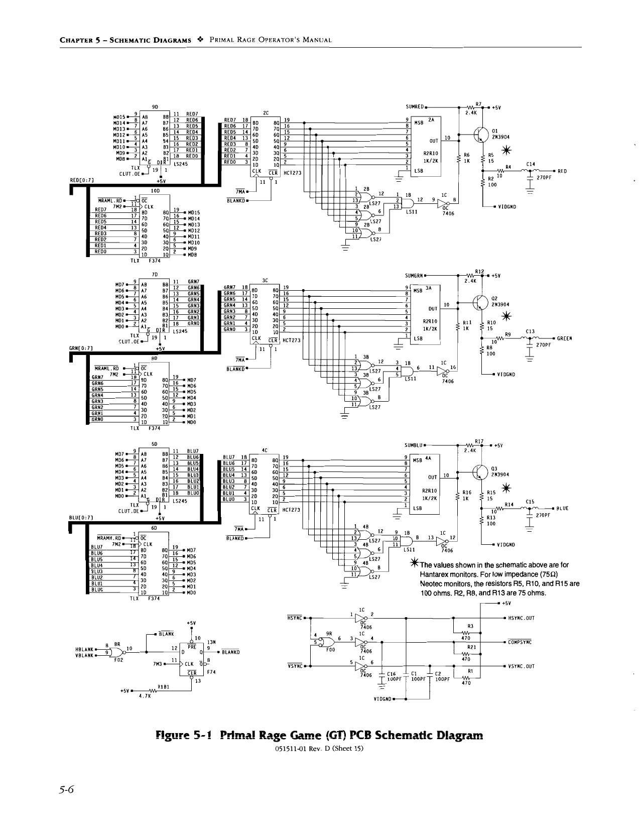
This page is a drawing, shown as the original scan.
PRIMAL RAGE OreraTor’s MANUAL @& CHAPTER 5 — SCHEMATIC DIAGRAMS
Sw GND
RIGHT COIN SW
LEFT COIN SW
GND
+5V AC
CHASSIS GND © enon be won A NC OR NO BK f i ' ' \ ' ' ' 1 ' ' \ ' ' \ i ne ' Right Coin Switch } y Nos C Bk ' BK_! Left Coin Switch i T oR! ' T ' you ' T \ \ ' \ ' \ ' \ ' \ ' \ ' BU! ' T \ GN! ' T ' GN ' ' ' ' BU ; \ | ew,( | ' \ \ ' \ \ ' \ ' '
Figure 5-2 Coin Door Wiring Diagram (049507-01 Rev. A
w NI
CHAPTER 5 — SCHEMATIC DiaGRAMS Primal RAGE OPERATOR'S MANUAL
cncae0
| ace qh tl? | ase | an |
cia owes 2
| ma | ows | r | bass | 2 | |
| tae fe OE | oc | con | ed | ||
| me eee | Cn | ed | GT | ae] | Meas are |
| mo ee | | ar] ® cea Wray | aa]! B Aarons | |||
| i: | snus | Ce gd CS mee ]N Bis aione a Weer | |||
| AE gare | won Me | ate 285, * | Aue reas, a | ||
| au eae | oo | Tale | a fe |
on ‘30
| san ea | wo | a0. | au | |||
| 88 Cea | me ES | ons [ | fone aos _ tons | CVE premeeeres Eat tae | ||
| ear | te 8 | ciaeap | ant saat | me]?! cme a | ||
| ine | ws Ge | wae | | wore 33 mse wane ware 6] | gs (bee ae STALE | ||
| +e | wre ey | cal yl | BOGIT 33 RS__FOATT | men se aS BTA | ||
| ie | 20 hi, | Coma | oes sas eT | ws) 2 ea, | ||
| i | ws i | a" | ca ase — a | aad | Ae Ee | ee |
| ‘ | ie hs | os | ® | Bale | ||
| to | wy | at | ||||
| oo | 1S Chinn at | = | = | |||
| oe | Se ee | 9% | sate | |||
| a | ors | ier tht | oa | sory st |
rr
| ae | oe | See] | baie Wise at | a | tree a | a |
| oxo | aad | ae | 8 a aoe are aoe | tae | tice —3\Wia—oie | |
| ™ | wf | ei aa | a | tara sai | ||
| aor | we peg LC OWA | _ Gu | DEOMALL BiAe | |||
| a | a | Taser — a | i | arta |
= % uo
= = we
- a:
vic oo
| ws | 9s | o_o ns | |||
| we] 8 Cea | aa] | Gane | |||
| ‘ | > | ee | |||
| ay | cian | ed a | |||
| vers | ae] | Soper | we | 8 Gone | |
| UNDEF? rie BOMDBS: | we |S 3 | CEs | is Le . | ||
| mort) ee | cen | tee 8 eer | ma! 8 ae | |||
| mera | ao | ae | ee | mae] | oe |
F285 a Fees a_& ipa tps one we
ee oan
ea a Ge ed
| Cie | ie 7 ms | Came Ps eg RIC = | |
| cn a | Le | es KO | |
| oie Soe | oe | ee | |
| oe | wari] | ear | a ee ce |
| a | as | a | Tar |
| oo | Cn a | we 100 * | |
| Gn | = a anh | goo | fry |
| oe | Ar | * |
a fA
Figure 5-3 GT24M8 PCB Schematic Diagram 053001-xx Rev. B (Sheet 1)
Primal RAGE OPERATOR'S MANUAL CHarrer 5 — SCHEMATIC DIAGRAMS
=
| os | as | © were wore | wer |
| 1 een | Lend | 4 | ine |
© fre wows :or™”
| me | © we wait | 20 |
aur i tin a PS FORE
2 ie Ey ie or ee
, + | ‘SOCKET.
Figure 5-3 GT24M8 PCB Schematic Diagram, Continued 05360L-xx Rev. B (Sheet 1)
Carrer 5 — SCHEMATIC DiaGRAMS @ PriMat Rar Operator's MANUAL
Figure 5-3 GT24M8 PCB Schematic Diagram 053601-xx Rev. B (Sheet 2)
PRIMAL RAGE OPERATOR'S MANUAL CHAPTER 5 — SCHEMATIC DIAGRAMS
Figure 5-3 GT24M8 PCB Schematic Diagram, Continued 053001L-8x Rev. B Sheet 2)
CuapTer 5 — SCHEMATIC DiAGrams “% Pximat. RAGE OPERATOR'S MaNuat
auagost9y
ioc0:151 erson
ria
orem 2 | oen
if if
ver MoHI oO re Monta 1 type mom. 2
als Gat
we | soot sooner we oe_| soccer
mo =
SHE TV ae passsee PEE a6 gasize8 *16 sosioee
2 laa aa a
Figure 5-3 GT24M8 PCB Schematic Diagram 05360i-xx Rev. B (Sheet 3)
PRIMAL RAGE OPERATOR'S Manual & CHAPTER 5 — SCHEMATIC DIAGRAMS
7] wostexe ane ms a9
Ea cares Tl aa
ar bs SI as oe = cy Ine 22 a 20
socxer
aa oJ? 2
Soom
aa] wate? BA as sosiexe Ba tas “Toons
mars] oy { 21_s00 aus pea CIC mao] °° aaa
taro | TE BIE
suo) °) ape zo _| socxer
PHO _ii as
a_i
‘ en
ae
Figure 5-3 GT24M8 PCB Schematic Diagram, Continued (053601-8x Rev. B (Sheet 3)
5-13
CHAPTER 5 — SCHEMATIC DIAGRAMS % PRIMAL RAGF OprRATOR’S MANUAL
FROM GAME BOARD
a 1o——« ato
oO KY oa sicnree 9 oa JiL0EK 10 98 gispRa1 1 a danuneN0 12 G9 JignreN 1 oe ISIN M4 ge Serv 16 oe TILT 16 oe YIRCOIN 17 ge vistanr2 28 Oe DUA 19 Q——8 a1000n24 20 oe JILEFTOA 21 oe s1Rtza 22 Ga DIFIREZ 23 oe 10928 24 oe S1000N28 25 Ga DILEFTB 20 oe IAT 27 oe HO 28 ow Gk Ao GND oa) co edrsy do ests Eo auto Foe sie Hom Ker J o—a seta oe s1L00K Co DISPIRI Hoe DiAUD® Noe vine oe v1eLuE Ra JV 06H 5 Ge OISLFTST Te OILCOIN Ue 1S TART Vow OUUPIA WO J1004NI4 fa SLLEFTIA Ya v1aTIA Poe MiReL mos AIR 88 Qa J100¥N18 ce oe JILEFTIS D0 Oe JiRTI8 FeO 9 OND FF O20
5-14 cea 28 @ en a is F z007F eas piety @ me os 2 22000
e26 stn pr a se =e 2200PF x7 oiiy ef anew TF reoonr
ce = siegmea ere seen 22007 cag sue »@] pm —e stone 2200 » t oa SPAR ger po a 2200RF can sen «Ferma sono 22009F
BREEN @ pa sonten Fre cas oisite enon sie
92968 @ ere os 2200°F e36 ane pf} nme att = 200rF
36 = pcb @ en pe zoe on staat: =F nome ssa 22000F
S126 @ rn ret 2200°F exg stots enn —e sinc 2 zz00re
SIE Te4 gen pr _ ter28 L z200rF ca gre, 9 Fane sae, 22000F
1&2 @ ree rite 2200°F cag stupas @ fn es 72000
cae = 0828 @ ep soe E z200%F cas seers xP pe sternes 22009
ces 28 eon a ae 220006 a S184 eon ai LE zea0rt cz o18y Pre ts 22000F
« JY em a st L ze007F ce ststay pee see 220007
Gy Se @ ep ent 2200°F og vincent ef npn —e soo 22000 IH
WHA o susie @ ep. =e spans 2e00PF cg en snus LP eeoare
c 21RD gp at 270F exo pie =} pra use a 0p
au = SURO @ erp oviind 22007F cae oistetst @——. asters
zener
as = anucoln Sa sucotw OOF Ge sastanny » Pn e gsrin zencee
as = 210A 9p 2200°F cis savawtig @— Frm ona i 22009F
a SULETIA @ ens —__—___aternia 220097 ce sas @ $F np a sata 7 72000
cy = sunt @ np a int 2200°F ¢29 gins a} pre ors 220006 nt ca 1008 @ arp sonwnts 2200°F cea suerte @——F enya sere 220096
a arene =e unis 22009
Figure 5-4 JAMMA fFiiter PCB Schematic Diagram
047292-01 B
Pximal RAGE Operator's MANuAL ¢ CHAPTER 5 — SCHEMATIC DIAGRAMS
To GAME HARNESS
ome G10 eo. Gio ro 215" @ 0 288 0 359 a0 oz) e—90 SONTR? @ 9 piceke s——o, JSPRRL a9 JAUOGNO @—o GREEN wo ASYNC sO SERV @—o STILT @—o ARCOM Bo SSTART2 #9, UPA sO woe @—O SLET2 BO BZA = 9, aI? @——9 oure8 so, sow28 <9, oLerT28 eo, onT28 = 9, Ho oo on = 9
oar 60 eo 60 w—9. us5¥ 90, ss5¥ 00. vive. wav a0
sewral eo 0x1 e—o ASPKRIE eo. sue sO RED ae —9 38WE a9 avi0sa a—o SSLFTST @—o StcorN a—o, ostakt @—— uPA a —0 avount ao SUEFTIA ao, JIA = wit e=—o SUFIB a sabe @—o sun e——o Jae 9 — 02 —o We —o
Figure 5-4 JAMMA Filter PCB Schematic Diagram aaa sama res sao eres ered en seated ees stat ‘et ee are AHR aM S ‘wT oaMs-u awa ¥ re aM saa AML 2 aM oanha- 88 sane ava-00 ania SRM
tea satate-2 ere) ered NHS tas ona aM 8 ee) dam 10 ama 11 santa 12 ene AMAL am-15 Sama 16 SAT anna 18 Rarer) cena 20 ‘ana Arar ete 23 Sat 24 et 25, ‘tet 25 “a 27 ‘net 28 (SPRR-L) 1 (GREEN), WI HOLE we Hig vue
«ska coxa) csv) ase) C50 crn
contr) (-U9eKL (SPRRSR) (Sem) ren) (Bue (v0 ox) (severest) (ooINL) srarrLy (ue COOANLAY (Ler CRIGHTLAD ‘uBuTToKd) (uayTToNe) «<cauTTOKDD {LEFTLB) (RGA LBD «sho) (exo)
047292-01 B
wv ne
This page reads as a drawing: its text was drawn rather than typeset, and comes out in fragments. See the original scan.
Primal RAGE Operator's Manual ¢ CHAPTER 5 — SCHEMATIC DIAGRAMS
ves 4
- —— ume 1 1 -_ 1 START, FAST. 1 I 1 a wen > | wen 2. I : wR ! we H _ _ : a Pa wor wan ¥ _ . i our z!
i a eyo : 4 wisn se vee a1 ! |
- oust 1 | t H “Lan se rie t \ 1 r 1 | 1 ’ 1 = I H I te f sik att ast ! ! mm new = | va sown 3 1 vom soon BT : H vi ssn ! en sie rence 7 : _ ws oom EL
7 i = | wi? Hl I
- » oi 8 i 1 re H t eo | VIDEO DISPLAY | oo [> / ! ms oo 2 { wr ts | ow Pow en cneen ~ 5 |= OL CH 31 AUDIO PCB vee . "
s| a] > ji) ar Spa ° el? | SPEAKER
i |/ <3 ” os " z FLUORES- voortas [a0 i rai 1 (\ CENT sooree a =r LIGHT go |F - ASSY. bal
POWER SUPPLY | reat fag ting agen
Figure 5-5 Primal Rage Game Wiring Diagram, Continued (053499-01 Rev. A
CHapTeR 5 — SCHEMATIC DIAGRAMS Primal, RAGE Operator's MaNval
X-Bus Host Interface
Code ROM
ROM Expansion Connector
Connected
Power Connector
Amplifier {in Stereo Version)
Audio Out
HHI)
Land R channels drive 8-Ohm speakers. Woofer drives 4-Ohm speaker. (Key) Left Channel + Left Channel — Right Channel + Right Channel — Woofer + Woofer —
Figure 5-6 CH31_2 (CAGE Audio) Board Block Diagram
5-18
This page carries no recoverable text. It is a drawing or a photograph. See the original scan.
This page carries no recoverable text. It is a drawing or a photograph. See the original scan.
This page carries no recoverable text. It is a drawing or a photograph. See the original scan.
This page carries no recoverable text. It is a drawing or a photograph. See the original scan.
fed ped eM e lel eN eM el ee ped pepe el ed eed elle eel pel fel pel ed pel el elelelel (ca
Warranty
Seller warrants that its printed-circuit boards and parts thereon are free from defects in material and workmanship under normal use and service for a period of ninety (90) days from date of shipment. Seller warrants that its video displays and laser-video disc players (in games supplied with displays and video-disc players) are free from defects in material and workmanship under normal use and service for a period of thirty (30) days from date of shipment. None of the Seller’s other products or parts thereof are warranted. If the products described in this manual fail to conform to this warranty, Seller's sole liability shall be, at its option, to repair, replace, or credit Buyer’s account for such products which are returned to Seller during said warranty period, provided:
- Seller is promptly notified in writing upon discovery by Buyer that said products are defective;
- Such products are returned prepaid to Seller’s plant; and
- Seller's examination of said products discloses to Seller’s satisfaction that such alleged defects existed and were not caused by accident, misuse, neglect, alteration, improper repair, installation, or improper testing. In no event shall Seller be liable for loss of profits, loss of use, incidental or consequential damages.
Except for any express warranty set forth in a written contract between Seller and Buyer which contract supersedes the terms herein, this warranty is expressed in lieu of all other warranties expressed or implied, including the implied warranties of merchantability and fitness for a particular purpose, and of all other obligations or liabilities on the Seller’s part, and it neither assumes nor authorizes any other person to assume for the Seller any other liabilities in connection with the sale of products by Seller.
REE e ere eee eee ere eee el elelelelelel ele
The use of any non-Atari parts may void your warranty, according to the terms of the warranty. The use of any non-Atari parts may also adversely affect the safety of your game and cause injury to you and others. Be very cautious in using non-Atari-supplied components with our games, in order to ensure your safety. Atari distributors are independent, being privately owned and operated. In their judgment they may sell parts or accessories other than Atari parts or accessories. Atari Games Corporation cannot be responsible for the quality, suitability or safety of any non-Atari part or any modification including labor which is performed by such distributor.
G-A_M EXS (Ss TIME WARNER INTERACTIVE
675. Sycamore Drive
~Milpitas, CA"95035 U.S.A. > (Fermerly knovn as Atari, Games Corporation) “Ss ~ Total Immersion Audio ™