Meteor by HOEI
Asteroids (rev 4) (Atari, 1979) · Manual · 13 pages · 14 sections · original scan
G METEORS'& UFO! + 360°ALL-DIRE AL FIRING POSSIBLE!
J EMERGENCY ESCAPE. OUR SPACESHIPI!
aE ) } ce
User Manual - Meteor by-HOET
Manual owned & scanned by ‘Level 42',.edited.by ‘speleo_de’
~ GAME INSPECTION -
This game is ready to play upon removal from the shipping carton. However, your careful inspection is needed to supply the final touch of quality control. Please follow these steps to help us insure that your new game was delivered to you in good condition.
- Examine the exterior of the game cabinet for dents, chips or broken parts.
- Unlock and open the rear access panel of the cabinet and inspect the interior of the game as follows: a. Check that all plug-in connectors (on the game harness) are firmly seated. Replug any connectors found unplugged, DON'T FORCE CONNECTORS TOGETHER. The connectors are numbered, b. Check that all plug-in integrated circuits on the game PCB are firmly seated in their sockets,
c. Check all major subassemblies such as the power supply, control panel and TV monitor for secure mounting.
- GAME INSTALLATION -
! Installation Requirements
Power 110 watts Temperature O to 40°C (32 to 104° F) Humidity Not over 95% relative Space Required 61x80cm Game Height - 172cm
- VOLTAGE SELECTION
Before plugging in your game, make sure that the voltage selection plug on the Set-down-Transformer is correct fob your location's line voltage.
117V 220V 2
Neutral i
Hot
- INTERLOCK and POWER ON/ OFF
To minimize the hazard of electrical shock while working on the inside of the game cabinet, interlock switch has been installed. It's located behind the rear access door. This switch remove all A.C. line power from the game circuitry when a door is opened.
Check for proper Operation of the interlock switch by performing the following steps:
- Unlock and open the access door.
- Plug the A.C. line power cord into an A.C. outlet.
- Close the access door,
- Within 30 seconds the TV monitor should display a picture.
- Slowly open the rear access door. The TV monitor picture should disappear when the door is opened approximately 2.5cm. Close and lock the access door.
- If the results of step 5 are satisfactory, the interlock switch is operating properly. If the TV monitor doesn't go off as described, switch is broken from its mounting or stuck in the on position.
- SELF-TEST PROCEDURE ~-
This game will test itself and provide data to demonstrate that the game's circuitry and controls are operating properly. The data is provided on the TV monitor and the game speaker, no additional equipment is necessary.
Part of the self-test procedure includes a display of the operatorselectable game options. Therefore, we suggest you run the self-test procedure anytime you need to change the game's option's.
To run the self-test, follow the instructions.
Self-test Switch
ervice Sw. Option Switches
Volume Control (decrease; turn clockwise)
LOCATION of SELF-TEST SWITCH, VOLUME CONTROL and OPTION SWITCH
~ SELF-TEST PROCEDURE -
INSTRUCTION RESULTS IF TEST PASSES RESULTS IF TEST FAILS
Set self-test switch to on position {TV monitor displays picture as shown in figure.
TV MONITOR DISPLAYS
LEFT COIN MECH MULTIPLIER.
Photograph wt RIGHT COIN MECH MULTIPLIER, swiTcH
shows toggles 1, 2, 47 on, and toggles 3 and 6 off.
- Activate all control panel and coin door switches. .L PLAYER START and 2 PLAYER START LEDs are lighted. Highpitched click for leach activated switch. RAM FAILURE is indicated by a sequence of from 1 to 6 tones. A low-frequency tone is heard for each good RAM chip. A much lower frequency is heard for a failing RAM chip. The sequence stops with the last failing RAM chip. To restart the sequence, press the Reset pushbutton on the game PCB or set the self-test switch to off, then again to the on position, Identify the bad RAM chip with table below. Example: Three tones, the a tone of much lower frequency indicates failure of RAM chip 9E. TONE # RAM CHIP LOCATION iL 1R 9D 9E oF 9G ROM/PROM FAILURE is indicated by two lines of numbers in the upper lefthand corner of the display. The number on the first line indicates the failing ROM/PROM chip(s). Identify the bad ROM/PROM with table below The number on the second line indicates the failing data bit of the failing ROM/PROM. Identify the bad bit with the second table below. If more than one bit is failing, the displayed number(s) are hexadesimal combinations of the numbers shown below. Examplés: L)If bits D2 & D3 fail, C is displayed. 2)If bits D2, D3 & D7? fail, 8C is displayed BIT(faiijD?7 Dé D5 D4 D3 D2 Dl Do Hexa- Q 0 0 0 0-007 O decimal |8 & 2 1 8 4& 2 i Du Ew
DISPLAY NO. FAILING PROM NONE WNM HO ROydyvQ oS
RAMSFL SIGNAL FAILURE is indicated by PAGE SELECT ERROR messege at lower middle of display. 1 PLAYER START and/or 2 PLAYER START LEDs not lighted. High-pitched click sound is not heard for any particular switch.
- OPTION SWITCH SETTING ~
To change toggle positions of the switch assembly, you need not remova the game PCB. The switch, usually colored black, is easily accessible when the game PCB is mounted in place.
When changing the options, verify proper results on the TV monitor
display during selfest, A switch toggle in the on position is indicated by a O for that switch on the TV monitor display. A switch in the off position is indicated by al.
TOGGLE SETTING of 8-TOGGLE SWITCH ON GAME PCB
1 2 3 4 5 6 ? 8 OPTION
ON ON OFF ON ON OFF OFF O8F
ON OFF
ON OFF
ON on OFF ON ON OFF OFF OFF
ON On OFF ON ON OFF OFF OFF Englieh Language German Language French Language Spanish Language 4-Ship Game 3-Ship Game Left Coin Mech xl Left Coin Mech x2
Right Coin Mech xl Right Coin Mech x§ Right Coin Mech x5 Right Coin Mech x6
Freo Play 1 Coin 2 Plays 1 Coin 1 Play 2 Coins 1 Play
~ GAME PLAY -
Hoei's Meteor game has five possible modes of Peration: attract ract, Ready-to-Play,Play, High Score Initial and Self-test. Selt-teat ig a special mode for checking the game switches and computer functions, You may enter this mode at any time. When entered, all game credits are cancelled.
- ATTRACT MODE
The attract modo begins when power is applied to the game,after a play or high score initial modo, or after self-test, This mode is continuous and is only interrupted when a coin inserted and accepted or when in self-test. In this mode, the TV monitor displays two possible pictures. Both pictures have three score values across the top of the screen and a messaga that states the number of coins for a game. The middle score represents the high score to date. The left score is for player 1, The right score is for player 2. One picture displays meteors and an occasional enemy spaceship "floating" across the screen. The second picture displays up to 10 of the highest scores since the game was last powered up or since the last self-test. These two displays alternate every 16 seconds.
- READY-TO-PLAY MODE This mode begins when sufficient coins have been accepted for a.one or two player game. It ends when the 1 PLAYER START or 2 PLAYER START pushbutton is pressed. When this mode begins, the message PUSH START flashes immediately below the center score at the top of the screen. The displayed pictures are otherwise the same as those shown in the attract mode.
- PLAY MODE The play mode begins when either start pushbutton is pressed. The mode ends when the player's last ship of the game is lost, If the 1 PLAYER START pushbutton is pressed, the following picture is displyed: the PLAYER 2's score disappears; the PLAYER l's score becomes 00, and the number of ships (3 or 4, depending on the operator's setting) for the game appears below that score. The message PLAYER 1 also appears below the high score to date. Two seconds after pressing the 1 PLAYER START button the PLAYER 1 message disappears, and the game ship appears at the center of the display. Four large meteors appear and drift in from the outer edges of the display. If the 2 PLAYER START pushbutton is pressed, the following picture is displayed: the PLAYER 1 and PLAYER 2 scores become 00, and the number of ships for the game appears below each score. The player 1 score also flashes as the message PLAYER 1 appears below the high score to date. Two seconds after the 2 PLAYER START pushbutton is pressed, the PLAYER 1 message disappears. The game ship for player 1 appears at the center of the display as four large meteors appear and drift in from outer edges of the display. By pressing the LEFT ROTATE and RIGHT ROTATE pushbuttons on the control panel, the player may aim a spaceship toward any of the meteors. By pressing the FIRE pushbutton, the player may shoot at the meteors.
When shot, each large meteor divides into two medium-sized meteurs and the game adds twenty points to the plyer's score. Medium-sized meteors, when shot, divide into two small-sized meteors, and the plyer receives fifty points, Small-sized meteor, when shot, will completely disappear, and the game awards 100 points to the player. When players have shot all meteors, a new sot of large meteore again appear and drift in from the outer edges of the TV monitor display. At the beginning of the game, four large meteors appear. At the beginning of the next cycle when large meteors reappear, there are six, the next time eight, and thereafter ten - to increase player challenge. At any time during game play, a flying saucer may appear from either side of the display. The game awards players 200 points for shooting a Jarge saucer and 1000 points for a small saucer. (The latter isa smaller target for players, through not any faster moving than the large one. It also shoots more accurately.) The player's objective in the game is to shoot and destroy as many meteors as possible before all his or her spaceships are destroyed. A ship is destroyed if an meteor or saucer smashes into it, or if a flying saucer shoots it. To prevent losing a ship, the player may press the THRUST pushbutton to move out of the path of an meteor or saucer. As an emergency maneuver, players can press the HYPERSPACE pushbutton: the ship disappears and reappears at a random location on the display however, possibly right on top of, or in the path of, an meteor, The ship may also explode on reetry. The game awards an extra ship each time a player's score reaches multiples of 10,000;i.e., one ship is awarded at 10,000 points, another ship at 20,000 points, etc. When the last ship of the game is destroyed, the message GAME OVER appears below the high score. This message remains for a 3 seconds before the high score initial mode begins,
- HIGH SCORE INITIAL MODE
At. the beginning of the high score initial mode, the player instructions appear at the top of the screen, and A_ | appears at the lower center of the display. Players enter initials ono character at a time. By pressing the LEFT ROTATE pushbutton, the displayed character steps through the alphabet from A to Z. By pressing the RIGHT ROTATE pushbutton, the character steps backwards through the alphabet from A to a blank, then from Z to A. Once the game displays the desired letter, players should press the HYPERSPACE pushbutton to record the letter; then an A appears in the next space.
If players need only two letters for their initials, they should use the biank between 2 and A in one of the three locations. Pressing the HYPERSPACE pushbutton a third time will cause the initials and game score to be transferred to the "10 highest scores" listing that appears during the attract mode,
3qdaes : ecceee eaGASASACHEACACACIGI A B5t2 gr ap Sf8iahe] ied weJbeig Bulli
POWER SOURCE ASS. SOLDER sibE fe COM PONENT
bla
FOR MONITOR (XY)
SP Ith
3P il was y ees PowER SvPLY BOAD ybh- Foo
Ysmod volver ayor A705 B FLUORESCENT LANP
eT
Door sw
plowen <P | a —____]
ELECT) \ Ac INPUT UPRIGHT TYPE YOA- #00 “EL.
SIDE
Guo 4ST #27 tS LF, =107? 4227 +120 oa a
Schematic Diagram - CPU & ROM / RAM
Schematic Diagram - Sound & I/O - VSM & D/A
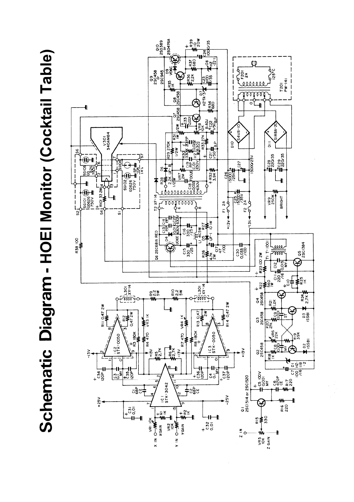
This page is a drawing, shown as the original scan.
Schematic Diagram - LAI Monitor 20" (Upright)
SCHEMATIC DIAGRAM (model LAI-KZ-20XYB) NOTES:
| Q501,0502 28C536 or 2SC945 2504 288632K IC 501 STK-0080 506 2SC536 or 2SC945 esistance values are in ohm. K = 1,000 M = 1,000,000
. Uniass otherwise noted in schamatic diagram, all capacitors less thas
ace expressed in mfd(uF) and the values larger than 1 ars in pF.
3. This is # fundamental circult diegram, Some production changes may
be made without revision of the diagram,
+ 30 3 a 6) 2801 Tore ie nse 288 o 0g0
0908 Pore + 0503 28536 or 28C945 9507 2SA608 or 2SA733,
Q601,Q602 250536 or28C945, 604 2SB632K 2606 25536 or 286945 Q607 2SA608 or 25A733 Q703 230313 702 28c2z74 Q70! 280536 or 2¢945 4208 ‘vaso: Fist Q20t 256536 or2SC945
L390 sizer cg
| Q603 250536 or 25C945 Q605 280325. IC60I STK-0080 ee Qe01 2SC536 " 280945 802 280400 Q803 2SD823K “ Bt
see the known archives, eg at http://arcarc.xmission.com/