Asteroids Cocktail DP-150-1st-01A
Asteroids (rev 4) (Atari, 1979) · Drawing Package · 1 pages · original scan
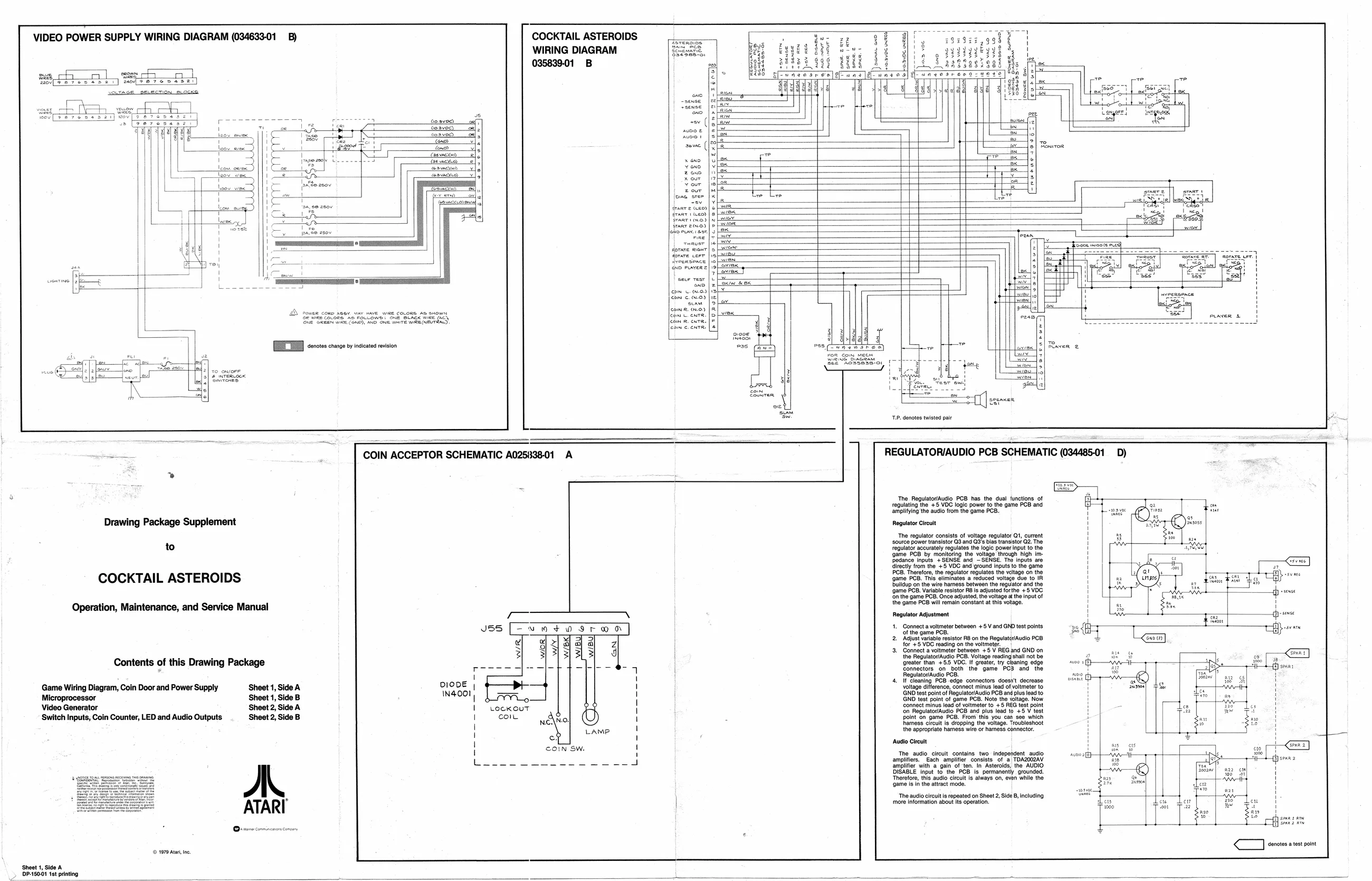
VIDEO POWER SUPPLY WIRING DIAGRAM (034633-01 _B) COCKTAIL ASTEROIDS WIRING DIAGRAM 035839-01 _B
cosved,
aves) onl ox ra Con mi __S Capvnexnd
Drawing Package Supplement
to
COCKTAIL ASTEROIDS
Operation, Maintenance, and Service Manual
Contents of this Drawing Package
Game Wiring Diagram, Coin Door and Power Supply Sheet 1, Side A
Microprocessor Sheet 1, Side B
Video Generator Sheet 2, Side A ‘Switch Inputs, Coin Counter, LED and Audio Outputs. Sheet 2, Side B
a
(© 1979 Ata, ne. [EI cots eae nine san so Sethe ice fe o> (|
seve (
START 1 (GEO)
em m0) eon ©.)
com. ew.0)
COIN ACCEPTOR SCHEMATIC A025838-01 A
DIODE | IN4001 | Lockout coll "Danae ono Choavoe eves! ToS] 3 |sreavoe onee ares.)
i t aR (ee
even T aesge plc vE@SAnE
ow FRO OnE
NSS is
‘The Regulator/Audio PCB has the dual functions of regulating the +5 VDC logic power to the game PCB and amplifying the audio from the game PCI Regulator Circuit ‘The regulator consists of voltage regulator Qt, current ‘source power transistor Q3 and Q3's bias transistor Q2. The tml acura ogling ower! 1 the 1@ PCB by monitoring the voltage through high im- Podance inputs, '+SENSE and SENSE. Te Inputs. are directly trom the +5 VDC and ground inputs to the game PCB. Therefore, the regulator regulates the veltage on the 1@ PCB. This eliminates a reduced voltage due to IR
Burdup on the wire harness between the Teguator andthe
‘game PCB. Variable resistor RB is adjust Ente ge PCB: Once adusted, he volage at the game PCB will remain constant at this votagé Regulator Adjustment D)
1+ Comect avetnater between + Vand GNP tet points Rajust table resistor RB on the RegulaterAudio PCB for +5 VOC reading on the voltmeter. Gontect a voimetet between +5 V REG and GND on the Regulator/Audio PCB. Voltage reading shall not be ‘greator than +55 VOC. If greater, try cleaning edge connectors on both the game PC3 and the Regulator/Audio PCB, If Cleaning PCB edge connectors doesn't decrease voltage difference, connect minus lead of voltmeter to GND test point of Regulator/Audio PCB and plus lead to GND test pont of game PCB. Note the yltage, Now Connect minus lead of voltmeter to + REG test point on RegulatovAudio PCB and plus cad to +0 V test point on game PCB. From this you can see which harness circuit is dropping the voltage. Troubleshoot the appropriate harness wire or hamess connector. ‘Audio Circuit ‘The audio circult contains two independent audio amplifiers. Each amplifier consists of a TDAZ002AV amplifier with a gain of ten. In Asteroids, the AUDIO DISABLE Input to the PCB Is permanently grou Therefore, this audio cru Is always on, even whi ‘game isin the atract mod ‘The audio circuit is repeated on Sheet 2, Side B, including ‘more information about its operation.
< onotes a test point