Rally-X Parts and Operating Manual (Jan 1981) (Bad Scan)
Rally X (32k Ver.?) (Namco, 1980) · Parts & Operating Manual · 75 pages · 52 sections · original scan
GAME NOS. 935, 936 & 937 ° _ MIDWAY’S |
AabLY-X
PARTS AND
OPERATING MANUAL
#937-MINI
#935-UPRIGHT #936-COCKTAIL
MIDWAY MFG. Co. e L/M 10750 WEST GRAND AVENUE
FRANKLIN PARK, ILLINOIS 60131
U.S.A.
PHONE: (312) 451-1360 CABLE ADDRESS: MIDCO TELEX NO:.: 72-1596 FORM NO. 0935-00300--0000
TABLE OF CONTENTS
Page No. GENERAL INSTRUCTIONS—RALLY-X UPRIGHT.................... 1 GENERAL INSTRUCTIONS—RALLY-X MINI...... 2 GENERAL INSTRUCTIONS—RALLY-X COCKTAIL 3-4 SETTING UP PROCEDURE .............-...0005 5 TROUBLE SHOOTING (GAME TESTS 5-7 SWITCH ADJUSTMENTS. . 8 PLAYING INSTRUCTIONS ... 9 NO. 935—RALLY-X UPRIGHT—PHOTOGRAPH . INTERIOR ACCESS PICTURE ................. NO. 937—RALLY-X MINI—PHOTOGRAPH ‘ INTERIOR ACCESS PICTURE NO. 936—RALLY-X COCKTAIL—PHOTOGRAPH INTERIOR ACCESS PICTURE .............. COCKTAIL CONTROL SHELF ASSEMBLY . CARD RACK ASSEMBLY ............. CONTROL ASSEMBLY ... PUSH BUTTON ASSEMBLY....... TRANSFORMER BOARD ASSEMBLY .. DOUBLE ENTRY COIN DOOR ASSEMBLY . : SINGLE ENTRY COIN DOOR ASSEMBLY ......... GAME BOARD COMPONENT LAYOUT—BOARD #1. GAME BOARD COMPONENT LAYOUT—BOARD #2................. 37 GAME BOARD SCHEMATIC—BOARD #1 .....................200-- 38 GAME BOARD SCHEMATIC—BOARD #2 ... 39 GAME BOARD #1 PART NO. & FUNCTION LIST 40 GAME BOARD #2 PART NO. & FUNCTION LIST 40 POWER SUPPLY COMPONENT LAYOUT.... 41 POWER SUPPLY SCHEMATIC ............. > : 42
CREDIT MULTIPLYER COMPONENT LAYOU 43 CREDIT MULTIPLYER SCHEMATIC........ 44 WIRING DIAGRAM—UPRIGHT (DOMESTIC) 45 WIRING DIAGRAM—UPRIGHT (FOREIGN) . 46 WIRING DIAGRAM—MINI (DOMESTIC) . : 47 WIRING DIAGRAM—MINI (FOREIGN) 48 WIRING DIAGRAM—COCKTAIL 49 19’’ MONITOR SCHEMATIC—WELLS-GARDNER . 50 REPLACEMENT PARTS LIST ................- 51—52 WELLS-GARDNER MONITOR ADJUSTMENTS . 53—56 19°" MONITOR SCHEMATIC—ELECTROHOME . 57 REPLACEMENT PARTS LIST .. 58—61 13’? MONITOR SCHEMATIC—ELECTROHOME 62 REPLACEMENT PARTSLIST ................ 63—66 ELECTROHOME MONITOR ADJUSTMENTS .....................-. 67—69
COPYRIGHT 1981 ©BYMIDWAYMFG.CO. —_ALLRIGHTS RESERVED.
NO PART OF THIS PUBLICATION MAY BE REPRODUCED BY ANY MECHANICAL, PHOTOGRAPHIC, OR ELECTRONIC PROCESS, OR IN THE FORM OF A PHONOGRAPHIC RECORDING, NOR MAY IT BE TRANSMITTED, OR OTHERWISE COPIED FOR PUBLIC OR PRIVATE USE, WITHOUT PERMISSION FROM THE PUBLISHER
FOR PERMISSION REQUESTS, WRITE: MIDWAY MFG. CO., 10750 W. GRAND AVE., FRANKLIN PARK, IL 60131
GENERAL INSTRUCTIONS FOR RALLY-X UPRIGHT
INSTALLATION
- Remove shipping cleats located on bottom of cabinet. . Install four (4) provided leg levelers to bottom of cabinet and level cabinet. . The power is controlled by a switch located on top of the cabinet. Additional taps have been provided on the transformer to compensate for fluctuating line voltage. . Upright only - To remove protective paper coating from decal - each side of cabinet, soak paper with water to soften and carefully start ‘‘peel back’’ of paper with fingernail. Peel paper parallel to cabinet side. ‘‘DO NOT PULL OUT”’. won
»
LINE VOLTAGE SAFETY SWITCH A line voltage safety switch has been provided for your protection. It is located on the right rear side of the cabinet in the back door area. When the back door is removed, it opens the circuit to the line voltage. To restore power (when servicing), pull switch fully out.
VOLUME CONTROL The volume control pot is located on the Game Logic Board (P.C. A082-91385-C000). This pot controls the volume of all sounds and may be varied as desired by rotating pot control.
ADJUSTMENT SWITCHES Located on Game Logic Board (P.C. A082-91385-C000) and may be adjusted as indicated on separate instruction card in back box area.
GAME LOGIC BRD. I(F) P.C. AQ82-91385-CO00
ADJUSTMENT. SWITCHES
VOLUME CONTROL
TO REMOVE CONTROL PANEL AND MONITOR DISPLAY GLASS
- Open coin door.
- Release two (2) clamps located below Control Panel on each side of cabinet.
- Disconnect control panel jack.
- Remove control panel.
- Remove monitor display glass.
CREDIT PUSH BUTTON SWITCH Located in cash box area and is readily accessible by opening coin door. This switch is provided as a test aid and awards one credit without advancing coin meter.
GENERAL INSTRUCTIONS FOR RALLY-X MINI
INSTALLATION
- Remove shipping cleats located on bottom of cabinet.
- Install four (4) provided leg levelers to bottom of cabinet and level cabinet.
- The power is controlled by a switch located on the back of the cabinet. Additional taps have been provided on the transformer to compensate for fluctuating line voltage.
LINE VOLTAGE SAFETY SWITCH A line voltage safety switch has been provided for your protection. It is located on the right rear side of the cabinet in the back door area. When the back door is removed, it opens the circuit to the line voltage. To restore power (when servicing), pull switch fully out.
VOLUME CONTROL The volume contro! pot is located on the Game Logic Board (P.C. A082-91385-C000). This pot controls the volume of all sounds and may be varied as desired by rotating pot control.
ADJUSTMENT SWITCHES Located on Game Logic Board (P.C. A082-91385-C000) and may be adjusted as indicated on separate instruction card in back box area.
GAME LOGIC BRD. I(F) P.C. A082-91385-CO00
ADJUSTMENT. SWITCHES
VOLUME CONTROL
TO REMOVE CONTROL PANEL AND MONITOR DISPLAY GLASS . Open coin door. Release two (2) clamps located below Control Panel on each side of cabinet. Disconnect control panel jack. Remove control panel. Remove monitor display glass. gReNa
TEST SLIDE AND CREDIT PUSH BUTTON SWITCH Located to right of cash box and is readily accessible by opening coin door. When placed in ““ON”’ position, this switch indicates test mode. The credit push button switch is provided as a test aid and awards one credit without advancing coin meter.
M051-00937-A003
GENERAL INSTRUCTIONS FOR RALLY-X COCKTAIL TABLE
INSTALLATION
- Remove shipping cleats located on bottom of cabinet.
- Install four (4) provided leg levelers to bottom of cabinet and level cabinet.
- The power is controlled by a switch located on the bottom of the cabinet. Additional taps have been provided on the transformer to compensate for fluctuating line voltage.
LINE VOLTAGE SAFETY SWITCH A line voltage safety switch has been provided for your protection. It is located in the cabinet on the left side of the coin door. When the coin door is opened the circuit to the line voltage is interrupted. To restore power (when servicing), pull switch fully out.
VOLUME CONTROL The volume control pot is located on the Game Logic Board (P.C. A082-91385-C000). The pot controls the volume of all sounds and may be varied as desired by rotating pot control.
ADJUSTMENT SWITCHES Located on Game Logic Board (P.C. A082-91385-C000) and may be adjusted as indicated on separate instruction card in back box area.
GAME LOGIC BRD. I(F) P.C. A082-91385-CO00
ADJUSTMENT. SWITCHES
VOLUME CONTROL
TEST SLIDE AND CREDIT PUSH BUTTON SWITCH Located to the right of cash box and is readily accesssible by opening coin door. When placed in “‘ON”’ position, this switch indicates test mode. The credit push button switch is provided as a test aid and awards one credit without advancing coin meter.
M051-00936-A003
TO SERVICE MONITOR, GAME BOARD AND TRANSFORMER ASSY.
- Open coin box door and release two (2) clamps indicated on sketch below.
- Grasp monitor mounting panel at ‘‘A’’ and open as indicated in sketch below.
ELECTRICAL BULLETIN: FOR ALL APPARATUS COVERED BY THE CANADIAN STANDARDS ASSOCIATION (CSA) STANDARD C22.2 NO. 1, WHICH EMPLOYS A SUPPLY CORD TERMINATED WITH A POLARIZED 2-PRONG ATTACHMENT PLUG.
ATTENTION: POUR PREVENIR LES CHOCS ELECTRIQUES NE PAS UTILISER CETTE FICHE POLARISEE AVEC UN PROLONGATEUR. UNE PRISE DE COURANT OU UNE AUTRE SORTIE DE COURANT, SAUF SI LES LAMES PEUVENT ETRE INSEREES A FOND SANS EN LAISSER AUCUNE PARTIE A DECOUVERT.
CAUTIONARY NOTES IN SETTING UP PROCEDURE
Care in Setting Up
- Place machine a sufficient distance from the wall and ona strong, level surface.
- Do not place in dusty or damp locations or where the sun’s rays will beat directly on the machine. Also, in order to avoid the interior of the machine’s overheating, do not place near heaters.
- Do not place in front of emergency or fire exits or in front of locations where fire fighting equipment or extinguishers are stored.
- Make sure the ground wire on machine is connected to the ground.
- Check to see whether all of the connectors on the PC boards, etc. are connected.
- Check if the electric power switch is turned ‘‘ON’’, and game is plugged in.
- Make sure the electric power is shut off when replacing parts or when removing connectors, etc.
- PC board repairs are to be done by the seller — do not handle in any case. Above all else, never conduct test with the tester, etc. The voltage in the tester can ruin the IC’s.
- When connecting the connectors, be careful not to reverse the direction of the connectors. When shipping PC boards use plastic airmats or other such protective material. When pulling the electric power source, always hold the plug — never pull the cord.
Self-Test The self-test is the same as the inspection of an automobile. If possible, it is best to do this each day. Rally-X has Self-Test capabilities and using the Test Switch most parts can be tested.
- Automatic Self-Test When the power in Rally-X is turned on the Self-Test automatically begins. If there is no problem in the PC boards it will change automatically into the ‘‘Attract Mode’, when there is a problem the Self-Test is repeated and the words ‘‘BAD RAM” or ‘‘BAD ROM’’ will appear on the screen. Even if the problem cannot be located, do not go on to other test switches or volume test, but carry out the Self-Test using the Test-Switch.
- Self-Test Using the Test Switch The slide switch on the opposite side when the selector switch is opened is the Test Switch. Turn the Test Switch ‘‘ON’’. The Self-Test will start (Normally this switch is OFF). The figures and words of the Test Mode will appear on the screen in 10 seconds.
RALLY-X TEST MODE
Game is in test mode for a moment immediately after power is turned on or when test switch is on. When test switch is returned to ‘‘OFF’’ the game goes into attract mode.
- ROM TEST The ROM data are checked 4K bytes at a time, and then checked together over all. If there are irregularities, the screen will display, for example, ‘‘ROM 1”’ or the like, identifying the bad ROM by number. The test series will not proceed to the RAM test. When there are no irregularties, ‘ROM OK”’ will be displayed and the RAM test will then be performed. The character ROM is not checked.
The position of the ROMs on the PCB as given by the ROM test message
Position of ROM and PCB
| ROM 2 | 1Dor1E | 1D |
| ROM 3 | 1H or 1J | 1H |
| ROM 4 | 1K or 1L | 1K |
MB8516 UPD2332 (EPROM) TMM333
- RAM TEST Each of the 12 ICCs numbered 2114 are checked and when any irregularity is found a message (e.g. RAM 1L) is displayed and the test series stops. If there are no irregularities tests of game sounds and switches can begin. The RAM test is performed only on ICCs numbered 2114
Position of RAMs on PCB as given by test message
- SWITCH & SOUND TEST The following sounds are made when switches are depressed:
SWITCH
Coin sw 1, 2 sound made when coin is deposited
plyr 1 cntrl sw smoke scrn
*plyr2cntrisw up sound made when one full pattern is cleared
*plyr 2cntrisw down
*Applies only to table model
If player one and player two’s smoke screen buttons are depressed at the same time, the display flip-flops and the smoke screen sound is made. If the test switch is pressed to off and back to on within one second while the smoke screen buttons are depressed, a cross-hatch pattern will appear. In the table model one edge and in the upright model two edges of the pattern will not appear.
SWITCH ADJUSTMENTS
METHOD OF PLAY (RALLY-X) SW. #1 SW. #2
| OFF | OFF | 1COIN, | 1CREDIT |
| OFF | ON | 41COIN, | 2CREDIT |
| ON | OFF | 2 COINS, 1 CREDIT | |
| ON | ON | FREE PLAY |
DIFFICULTY & NUMBER OF CARS PER CREDIT
| SW. #3 | SW. #4 | SW. #5 | ||
| ON | ON | ON | LOW DIFF, 2CARS | |
| ON | ON | OFF LOW DIFF, 3CARS | ||
| ON | OFF | ON MID DIFF, 1CARS | ||
| ON | OFF | OFF MID DIFF,2CARS | ||
| OFF | ON | ON | MID | DIFF,3CARS |
| OFF | ON | OFF HIGH DIFF, 1 CARS | ||
| OFF | OFF | ON HIGH DIFF, 2CARS | ||
| OFF | OFF | OFF HIGH DIFF, 3 CARS |
BONUS CARS SW.#6 = SW. #7
| ON | OFF | 1 CAR GAME 10,000 PTS. |
2CAR GAME 15,000 PTS. 3 CAR GAME 20,000 PTS.
| OFF | ON | 1 CAR GAME 20,000 PTS. |
2 CAR GAME 30,000 PTS. 3 CAR GAME 40,000 PTS.
| OFF | OFF | 1 CAR GAME 30,000 PTS. |
2 CAR GAME 40,000 PTS. 3 CAR GAME 60,000 PTS. SW. #8 OFF PLAY MODE ON LOCKS PICTURE
M051-00935-A014
PLAYING INSTRUCTIONS
1 or 2 persons can play.
By moving the control level, ‘‘My Car’’ (blue) can be moved up, down, right and left.
Avoiding barriers, use a smoke screen on the pursuing red cars.
With the help of the radar screen touch the check points, clear and continue on. There are 10 check points per round, one of which is the Special Check Point.
Check Point points When cleared Points 1st 100 2nd 200 3rd 300 4th 400 5th 500 6th 600 7th 700 8th 800 gth 900 10th 1000
When an accident occurs (hitting a barrier or red car) you must start over from the first 100 points.
When the Special Check Point is cleared, the points accumulated up to that time are doubled (the screen shows X2). Of course when an accident occurs, this score is wiped out.
Fuel.....‘‘My Car’’ starts off with a full tank (60 L.). When all check points are cleared, an additional 100 pts. is awarded for each 1 liter of fuel remaining. And, when a smoke screen is produced, the fuel decreases by 3 liters. When the fuel remaining reaches the 10L. level, the fuel indicator turns red and a warning is sounded. When the gas is all used, the car’s speed will gradually decrease and come to a stop.
Challenging Stage - Rounds 3, 7, 11, 15....are ‘‘Challenging’’, here 8 red cars appear but cannot run until the fuel in ‘‘My Car’’ is used up. Because ‘‘My Car’’ runs at full speed, it’s fuel is soon gone. Clear all check points before the blocking red cars can move. When this stage ends, starting with the nexi round the scene changes to city streets.
NO. 935 — RALLY-X UPRIGHT — PHOTOGRAPH
WAY MFG. CO. PAGE 10 MIDWAY MFG. CO.
NO. 935 — RALLY-X UPRIGHT — PHOTOGRAPH ORDER BY PART NUMBER ONLY jivem] parr No [ DESCRIPTION, 0935-00902-0000 DECORATIVE PLEXI - UPPER 23” x 9-1/16” x 3/16” 0866-00103-00XF PLEX! RETAINING BRKT. (2 REQ’D.) 0017-00101-0066 #10 x 5/8 PHIL. HD. SCR. (6 REQ’D.) 6935-00901-80XF MAIN DISPLAY GLASS-TEMPERED 23” x 2-1/8” x 3/16" 0935-00905-0000 DECAL - SIDE OF CABINET (2 REQ’D) 0017-00003-0339 19” DUAL SYNC COLOR MONITOR - ELECTROHOME A866-00064-0000 T.V. BEZEL & PLEXI ASSY. 9935-00900-0000 CONTROL SHELF OVERLAY 0935-00100-00XF CONTROL PLATE 0017-00101-0118 #8-32 x 1-1/8 CARRIAGE BOLT (6 REQ’D.) 0017-00104-0022 #8 WASHER (6 REQ’D.) 0077-00103-0061 #8-32 HEX NUT W/SEMS (6 REQ’D.) 0017-00101-0065 #6 x 1/2 PHIL. TRS. HD. SCR. (2 REQ’D.) A855-00016-0000 PUSH BUTTON ASSY. (2 REQ’D.) A932-00008-0000 CONTROL ASSY. 0017-00032-0651 SMALL RED SWITCH BUTTON W/HARDWARE (2 REQ’D.) 6017-00003-0187 6” x 9” SPEAKER, 8 OHM, 9W. 0017-00009-0393 BLACK SPEAKER GRILL W/4, 1-1/2” SCREWS 0151-00055-0100 DOUBLE ENTRY COIN DOOR ASSY. 0090-00002-02B K COIN DOOR FRAME 0017-00101-0121 #6-32 x 5/16 PHIL. TRS. HD. SCR. (3 REQ’D.) (MOUNTS COIN DOOR TO FRAME) 0017-00102-0048 3/8-16 x 2” LEG LEVELERS (4 REQ’D.) 0017-00103-0026 3/8-16 LEG LEVELER HEX NUTS (4 REQ’D.) NOT SHOWN LIST A866-00068-0000 DISPLAY LAMP BRKT. ASSY. (BEHIND ITEM #1) 0017-00003-0135 LAMP SOCKET (2 REQ’D.) 0617-00003-0309 LAMP 12V., 25W. (2 REQ’D.) 0017-00101-0626 #8-32 x 3/4 SLT. PAN HD. M.S. (4 REQ’D.) 0017-00103-0061 #8-32 HEX NUT W/SEMS (4 REQ’D.) 0017-00101-0025 #8 x 1/2 SLT. HEX HD. BLK. WD. SCR. (4 REQ’D.) 0017-00009-0033 BASSICK CLAMP (2 REQ’D.) 0603-00131-0000 STRIKE (2 REQ’D.) 0017-00101-0028 #8 x 3/4 SLT. HEX. HD SCR. (4REQ’D. CLAMP, 4 REQ’D. STRIKE) 0935-00906-0190 KICK PLATE (BASE OF CABINET) 0935-00907-0000 DECAL - (CABINET FRONT) MIDWAY MFG. CO. A BALLY COMPANY PAGE 11
NO. 935 — RALLY-X UPRIGHT — INTERIOR ACCESS PICTURE
MIDWAY MFG. CO. PAGE 12 A BALLY COMPANY
NO. 935 — RALLY-X UPRIGHT — INTERIOR ACCESS PICTURE ORDER BY PART NUMBER ONLY |ITEM| PART NO DESCRIPTION 0586-00036-0000 ON/OFF SWITCH 0567-00106-0100 SWITCH MTG. BRKT. 0017-00101-0028 | #8x3/4SLT. HEX HD. WD. SCR. (4 REQ’D.) 0017-00009-0490 5-5/8” SQ. VENT GRILL (2 REQ’D.) A935-00006-0000 | ELECTROHOME- 19” COLOR MONITOR W/CHASSIS, DUAL SYNC HORIZONTAL TUBE (OR) 0017-00003-0354 WELLS-GARDNER - 19” COLOR MONITOR W/CHASSIS, DUAL SYNC HORIZONTAL TUBE 0935-00101-0000 MONITOR MTG. BRKT. (2 REQ’D.) 0017-00102-0066 4/4-20 x 1-1/4 UNSLOTTED FIN. HEX HD. BOLT (4 REQ’D.) 0017-00104-0005 SPLIT WASHER (4 REQ’D.} 0017-00032-0071 INTERLOCK SWITCH A866-00035-00XF | INTERLOCK SWITCH BRKT. ASSY. A084-90414-C935 | POWER SUPPLY ASSEMBLY 0624-00902-0100 P.C. SUPPORT BRKT. - 12” (2REQ’D.) 0624-00902-0200 P.C. SUPPORT BRKT. - 6-1/2” (2 REQ’D.) 0017-00101-0027 | #8x3/4SLT. HEX HD. SCREW (10 REQ’D.) 0017-00104-0037 #8 FLAT WASHER (10 REQ’D.) A935-00008-0000 | CARD RACK ASSEMBLY A935-00007-0000 | TRANSFORMER BOARD ASSEMBLY
ADDITIONAL PARTS LIST 0017-00009-0477 CASH BOX - MOLDED A905-00026-0000 CASH BOX COVER ASSY. A624-00001-0000 CASH BOX GUIDE BRKT. ASSY. 0624-00101-0000 CASH BOX SIDE CHANNEL 0017-00101-0628 #8-32 x 3/4 CARRIAGE BOLT (4 REQ’D.) 0017-00104-0022 #8 WASHER (4 REQ’D.) 0017-00103-0061 #8-32 HEX NUT W/SEMS (4 REQ’D.) A151-00029-0000 LOCK ASSY. - BACK DOOR 0017-00004-0022 304 DYMAX STRAP A866-00036-0000 TEST SWITCH & BRKT. ASSY. 0866-00126-0000 MONITOR BRKT. (4 REQ’D.)
MIDWAY MFG. CO. A BALLY COMPANY PAGE 13
NO. 937 — RALLY-X MINI — PHOTOGRAPH
MIDWAY MFG. CO. PAGE 14 A BALL COMPANY
NO. 937 — RALLY-X MINI — PHOTOGRAPH ORDER BY PART NUMBER ONLY jirem| PART NS | 0937-00901-00XF UPPER DISPLAY PLEXI - 17-15/16” x 5-3/4”’ x 3/16” A905-00014-0000 INSERT ASSEMBLY 0017-00003-0219 #194 WEDGE BASE LAMP 14V., 27A (5 REQ’D.) 0017-00031-0030 LIGHT SOCKET (5 REQ’D.) 0905-00115-00XF TOP BRKT. 0905-00116-00XF BOTTOM BRKT. 0017-00101-0117 #8 x 5/8 PHIL. TRS. HD. SCR. (3 REQ’D. TOP, 3 REQ’D. BOTTOM) 0017-00009-0393 BLACK SPEAKER GRILL W/4- 1-1/2” SCREWS A762-00028-0000 6’ x9” SPEAKER ASSY. W/CABLE, 8 OHM, 7W. 0017-00101-0642 #8-32 x 1-1/2’? CARRIAGE BOLT (4 REQ’D.) 0017-00103-0061 #8-32 HEX NUT W/SEMS (4 REQ’D.) 0017-00104-0022 #8 FLAT STL. WASHER (4 REQ’D.) A937-00005-0000 MAIN GLASS ASSY. - 17-13/16”’ x 13-1/8”’ x 3/16” 0017-00003-0340 13” COLOR MONITOR DUAL SYNC HORIZONTAL MTG. - ELECTROHOME A937-00006-0000 T.V. BEZEL ASSY. 0905-00903-0100 GLASS CHANNEL - 14-1/2” LG. (2 REQ’D.) 0905-00102-00XF GLASS CLAMPING PLATE 0017-00101-0639 #8-32 x 1-1/4 CARRIAGE BOLT (3 REQ’D.) 0017-00104-0037 #8 WASHER (3 REQ’D.) 0017-00103-0009 #8-32 WING NUT (3 REQ’D.) A855-00016-0000 PUSH BUTTON ASSY. (2 REQ’D.) A932-00008-0000 CONTROL ASSEMBLY 0017-00032-0051 SMALL RED SWITCH BUTTON W/HARDWARE (2 REQ’D.) 0937-00902-0000 DECORATIVE CONTROL SHELF OVERLAY 0937-00100-00XF CONTROL PLATE 0017-00101-0118 #8-32 x 1-1/8 CARRIAGE BOLT (6 REQ’D.) 0017-00104-0022 #8 WASHER (6 REQ’D.) 0017-00103-0061 #8-32 HEX NUT W/SEMS (6 REQ’D.) 0017-00101-0065 #6 x 1/2 PHIL. TRS. HD. SCR. (2 REQ’D.) 0151-00055-0100 DOUBLE ENTRY COIN DOOR ASSY. 0090-00002-02BK COIN DOOR FRAME 0017-00101-0121 #6-32 x 5/16 PHIL. TRS. HD. SCR. (3 REQ’D.) (MOUNTS COIN DOOR TO FRAME) 0017-00102-0048 3/8-16 x 2’? LEG LEVELERS (4 REQ’D.) 0017-00103-0026 3/8-16 LEG LEVELER HEX NUTS (4 REQ’D.)
MIDWAY MFG. CO. A BALLY COMPANY PAGE 15
NO. 937 — RALLY-X MINI — INTERIOR ACCESS PICTURE
O) @)
@
(®)
©)
(4)
(8)
@)
MIDWAY MFG. CO. PAG E 1 6 A BALLY COMPANY
NO. 937 — RALLY-X MINI — INTERIOR ACCESS PICTURE ORDER BY PART NUMBER ONLY jirem] part Ne | DESCRIPTION 0017-00032-0083 ON/OFF SWITCH 0567-00106-0100 ON/OFF SWITCH PLATE A762-00028-0000 6” x9’ SPEAKER ASSY. W/CABLE, 8 OHM, 7W. 0618-001 17-00XF VENT GRILL 0017-00101-0015 #6 x 1/2 SLT. HEX HD. SCR. (4 REQ’D.) 0017-00003-0340 13” COLOR DUAL SYNC HORIZONTAL MONITOR & CHASSIS - ELECTROHOME 0017-00102-0013 1/4-20 x 1-1/4 CARRIAGE BOLT (4 REQ’D.) 0017-00104-0014 PERIPHERY WASHER (4 REQ’D.) 00717-00103-0018 1/4-20 HEX NUT (4REQ’D.) 0017-00032-0071 INTERLOCK SWITCH A866-00035-00XF \NTERLOCK SW. BRKT. ASSY. A084-90414-C935 POWER SUPPLY ASSEMBLY 0624-00902-0100 P.C. SUPPORT BRKT. - 12” (2 REQ’D.) 0624-00902-0200 P.C. SUPPORT BRKT. -6-1/2 (2 REQ’D.) 0017-00101-0027 #8 x 3/4 SLT. HEX HD. SCREW (10 REQ’D.) 0017-00104-0037 #8 FLAT WASHER (10 REQ’D.) A935-00008-0000 CARD RACK ASSY. A935-00011-0000 TRANSFORMER BOARD ASSY. - NOT SHOWN LOCATED BEHIND CARD RACK ASSY. 0017-00009-0490 5-5/8”’ SQ. VENT GRILL (2 REQ’D.) A905-00028-0000 CASH BOX ASSY. W/HANDLE A905-00026-0000 CASH BOX COVER ASSY. A624-00001-0000 CASH BOX GUIDE BRKT. ASSY. 0624-00101-0000 CASH BOX GUIDE BRKT. 0017-00101-0628 #8-32 x 3/4 CARRIAGE BOLT (4 REQ’D.) 0017-00104-0022 #8 WASHER (4 REQ’D.) 0017-00103-0061 #8-32 LOCK NUT W/SEMS (4 REQ’D.) ADDITIONAL PARTS A151-00029-0000 LOCK ASSY. - BACK DOOR 0017-00004-0022 304 DYMAX STRAP 0017-00009-0033 LATCH CLAMP (2 REQ’D.) 0603-00131-00XF STRIKE 0017-00101-0028 #8 x 3/4 SLT. HEX HD. SCR. (4 REQ’D. CLAMP, 4REQ’D. STRIKE) 0597-00124-00B0 BACK DOOR CUP 0017-00101-0129 #10-32 x 1”? CARRIAGE BOLT (3 REQ’D.) 0017-00103-0081 #10-32 HEX NUT W/SEMS (3 REQ’D.) A866-00036-0000 TEST SWITCH & BRKT. ASSY.
cae tds Ge. PAGE 17
NO. 936 — RALLY-X COCKTAIL — PHOTOGRAPH
MIDWAY MFG. CO. PAGE 18 ABALLY COMPANY
NO. 936 — RALLY-X COCKTAIL — PHOTOGRAPH ORDER BY PART NUMBER ONLY irem| PART NO DESCRIPTION 0936-00902-0000 | COVERGLASS-32” x22” x 1/4” 0775-00104-00XF | GLASS CLIPS (8 REQ’D.) 0017-00101-0117 | #8x5/8 PHIL. TRS. HD. SCR. (16 REQ’D.) 0017-00003-0334 | 19” DUALSYNC COLOR MONITOR - ELECTROHOME 0936-00903-0000 | PLEXI-GLASS 0921-00901-0000 | T.V. BEZEL A936-00004-0000 | CONTROL SHELF ASSY. - PLAYER #1 A936-00005-0000 | CONTROL SHELF ASSY. - PLAYER #2 0017-00009-0393 | BLACK SPEAKER GRILL (4 REQ’D.) 0017-00101-0639 | #8-32 x 1-1/2 CARRIAGE BOLT (16 REQ’D.) 0017-00103-0061 | #8-32 HEX NUT W/SEMS (16 REQ’D.) 0151-00055-0200 | SINGLE ENTRY COIN DOOR ASSY. 0090-00002-018K | COIN DOOR FRAME 0017-00101-0121 | #6-32x5/16 PHIL. TRS. HD. SCR. (3 REQ’D.) 0017-00102-0048 | 3/8-16x2" LEG LEVELERS (4 REQ’D.) 0017-00103-0026 | 3/8-16 LEG LEVELER HEX NUTS (4 REQ’D.) G927-00005-0000 | COCKTAIL TABLE - HIGH BASE - LEG KIT INCLUDING WHIZ BOLTS, WASHERS & LEGS (4 REQ’D.) (OPTIONAL) NOT SHOWN LIST 0610-00132-0000 STRIKE (2 REQ’D.) 0017-00101-0028 #8 x 3/4 HEX HD. S.M.S. (4 REQ’D.) 0017-00009-0033 BASSICK CLAMP (4 REQ’D.) 0017-00101-0026 #8 x 5/8 HEX HD. S.M.S. (4 REQ’D.) A749-00003-0000 COIN BOX ASSY. A627-00056-0000 COIN BOX COVER ASSY. A625-00024-0000 COIN BOX GUIDE BRKT. ASSY. 0625-00117-0000 COIN BOX SIDE CHANNEL 0017-00101-0628 #8-32 x 3/4 CARRIAGE BOLT (4 REQ’D.) 0017-00103-0008 #8-32 HEX NUT (4 REQ’D.) 0017-00004-0022 304 DY MAX STRAP A749-00005-0000 INTERLOCK SWITCH ASSY. A866-00036-0000 TEST SW. & BRKT. ASSY.
Me owemn CO PAGE 19
NO. 936 — RALLY-X COCKTAIL — INTERIOR ACCESS PICTURE
MIDWAY MFG. CO. PAGE 20 A BALLY COMPANY
NO. 936 — RALLY-X COCKTAIL — INTERIOR ACCESS PICTURE ORDER BY PART NUMBER ONLY
0017-00003-0334
A921-00010-00XF 0017-00101-0642 0017-00104-0031 0017-00103-0061 A889-00017-0000 0017-00009-0495 0017-00101-0639 0017-00103-0061 0927-00100-00XF 0936-00900-0000 0936-00901-0000 0017-00101-0620
0017-00104-0022
0017-00103-0061
0017-00101-0341
A932-00008-0000 0017-00032-0051
A855-00016-6000 A935-00008-0000 A936-00011-0000 A084-90414-C935 0624-00902-0100 0017-00101-0017 0017-00104-0031 0017-00032-0083 0567-00106-0100 0017-00003-0187 A775-00013-0000 0017-00003-0222 0775-00110-00XF 0870-00100-00XF 0017-00101-0347 0017-00104-0009 0017-00103-0005 0017-00101-0026 19” DUAL SYNC VERTICAL COLOR MONITOR & CHASSIS - ELECTROHOME MONITOR MTG. BRKT. ASSY. (2 REQ’D.) #8-32 x 1-1/2 CARRIAGE BOLT (4 REQ’D.) #8 FLAT WASHER (4 REQ’D.) #8-32 HEX NUT W/SEMS (4 REQ’D.) LATCH SLIDE ASSY. (TABLE TOP PROP) 2” HINGE (2 REQ’D.) #8-32 x 1-1/4 CARRIAGE BOLT (8 REQ’D.) #8-32 HEX NUT W/SEMS (8 REQ’D.) CONTROL PANEL (2 REQ’D.) DECORATIVE OVERLAY - PLAYER #2 DECORATIVE OVERLAY - PLAYER #1 #8-32 x 1/2 CARRIAGE BOLT (4REQ’D. EACH FOR PLAYER #1 & #2) #8 FLAT WASHER (4 REQ’D. EACH FOR PLAYER #1 & #2) #8-32 HEX NUT W/SEMS (4 REQ’D. EACH FOR PLAYER #11 & #2) #6x 1/4 PHIL. TRS. HD. SCR. (2 REQ’D. EACH FOR PLAYER #1 & #2) CONTROL ASSY. (2REQ’D.) SMALL RED SWITCH BUTTON (2 REQ’D.) - (PLAYER #1 SIDE ONLY) PUSH BUTTON ASSY. (2 REQ’D.) CARD RACK ASSY. TRANSFORMER BOARD ASSY. POWER SUPPLY ASSY. P.C. SUPPORT BRKT. - 12” (3 REQ’D.) #6 x 1/2 SLT. HEX HD. SCR. (9 REQ’D.) STL. WASHER (9 REQ’D.) ON/OFF SWITCH 120V, 6A. ON/OFF SWITCH MTG. PLATE 6’’x 9” SPEAKER 8 OHM, SW. FAN ASSY. (NEXT 7 PART NO’S) FAN FAN PLATE VENT SCREEN #6-32 x 1/2 PHIL. R.H.M.S. SEMS (4 REQ’D.) #6 EXT. WASHER (4 REQ’D.) #6-32 HEX NUT (4 REQ’D.) #8x 5/8 SLOT. HEX HD. S.M.S. (4REQ’D.)
MIDWAY MFG. CO. ABALLY COMPANY DESCRIPTION
NO. 936 — RALLY-X COCKTAIL — CONTROL SHELF ASSEMBLY
PAGE 22 MIDWAY MFG. CO.
NO. 936 — RALLY-X COCKTAIL— CONTROL SHELF ASSEMBLY ORDER BY PART NUMBER ONLY item] PART No DESCRIPTION 0927-00100-00XF | CONTROL PANEL A932-00008-0000 | CONTROL ASSEMBLY - SEE SEPERATE DETAIL A855-00016-0000 | PUSH BUTTON ASSY. -SEE SEPERATE DETAIL 0017-00031-0044 | WEDGE BASE LAMP SOCKET (2 REQ’D. PER CONTROL) 0017-00101-0555 | #6-32x 5/16 SLT. HEX HD. SCR. (2 REQ’D. PER CONTROL) 0017-00003-0219 | #194 WEDGE LAMP 14V., .27A. (2REQ'’D. PER CONTROL) 0921-00903-0000 | LIGHT SHIELD A936-00006-0000 | CONTROL SHELF CABLE ASSY. - PLAYER #1 A936-00007-0000 | CONTROL SHELF CABLE ASSY. - PLAYER #2
MO um ©O- PAGE 23
RALLY-X — CARD RACK ASSEMBLY
MIDWAY MFG. CO. PAG E 24 A BALLY COMPANY
RALLY-X — CARD RACK ASSEMBLY ORDER BY PART NUMBER ONLY [em] part No | (DESCRIPTION A082-91385-C000 GAME LOGIC BOARD ASSY. - BOARD #1 A082-91387-C000 GAME LOGIC BOARD ASSY. - BOARD #2 A935-00015-0000 HOLDER PLATE & STOP ASSY. (2 REQ’D.) 0017-00009-0478 NYLON GUIDE (4 REQ’D.) 0935-00105-0000 RETAINER (2 REQ’D.) 0935-00103-0000 SIDE SUPPORT (2 REQ’D.) 0935-00102-0000 MOUNTING BRACKET (2 REQ’D.) 0017-00101-0096 #6 x 3/8 SLT. HEX HD. SCR. (14 REQ’D.)
Me dteer® - PAGE 25
A BALLY COMPANY MIDWAY MFG. CO. RALLY-X — CONTROL ASSEMBLY
RALLY-X — CONTROL ASSEMBLY
ORDER BY PART NUMBER ONLY
DESCRIPTION
A932-00022-0000 SHAFT & BALL ASSY. 0017-00100-0025 1/4” E-RING 0921-00702-0000 STOP SPACER 0921-00902-0000 SLIDE PLATE A932-00011-00XF SPOT WELD ASSY. 0017-00101-0713 #8-32 x 1’’ SLT. FLAT HD. SCREW (4 REQ’D.) 0017-00103-0061 #8-32 HEX NUT W/SEMS (4 REQ’D.) 0932-00902-0000 GROMMET 0017-00101-0598 #8-32 x 5/16 SLT. HEX HD. M.S. (10 REQ’D.) 0921-00701-0000 SLEEVE 0017-00101-0528 #5-40 x 3/4 SLT. RND. HD. SCR. (8 REQ’D.) 0020-00202-0000 SWITCH PLATE (4 REQ’D.) A932-00009-0000 SWITCH ASSEMBLY (4 REQ’D.) A932-00012-00XF STOP PLATE & SWITCH BRKT. ASSY. 0932-00904-0000 WEAR PLATE 0921-00700-0000 ACTUATOR 0017-00100-0115 7/16” E-RING 0017-00104-0111 NYLON FLAT WASHER
TRAVEL OF PT. NO. 921-00700-0000 ACTUATOR IS APPROX. 1/8. SWITCH BLADE ASS’Y. SHOULD BE ADJUSTED TO MAKE CONTACT AT 1/16 OF ACTUATOR TRAVEL. TYPICAL 4. WONOuhwn a
- 0017-00101-0577 a 0020-00202-0000
0921-00700-0000 A932-00009-0000
MIDWAY MFG. CO. A BALLY COMPANY PAGE 27
RALLY-X — PUSH BUTTON ASSEMBLY
MIDWAY MFG. CO. PAGE 28 ABALLY COMPANY
RALLY-X — PUSH BUTTON ASSEMBLY ORDER BY PART NUMBER ONLY item] PART NO DESCRIPTION 0017-00009-B384 BUTTON - RED 0010-00242-0000 SPRING 0017-00009-0376 BUTTON HOUSING 0017-00104-0028 FLAT WASHER (2 REQ’D.) 0017-00100-0025 1/4” E-RING A855-00016-0000 PUSH BUTTON ASSY. (FIRST 5ITEMS) A927-00011-0000 MOUNTING BRKT. ASSY. - (COCKTAIL) 0586-00107-0000 MOUNTING BRKT. - (UPRIGHT & MINI ONLY) 0077-00103-0054 PAL NUT A739-00016-0000 SWITCH ASSEMBLY 0020-00202-0000 SWITCH PLATE 0017-00101-0526 #5-40 x 9/16 PHIL. HD. M.S. (2 REQ’D.)
rare e Go. PAGE 29
ATSINASSV GUVO8 HAINYOSSNVYL — X-ATIVY
RALLY-X — TRANSFORMER BOARD ASSEMBLY ORDER BY PART NUMBER ONLY
| 1 | MT00-00082-0000 | TRANSFORMER 115 VOLT |
| 2 | MT00-00087-0000 | | TRANSFORMER 240 VOLT |
3 | 0017-00003-0114 NOISE FILTER 4 | A031-00002-0000 TERMINAL STRIP ASSY. (2 REQ’D.) 5 | 0064-030XX-XXPX | DIODE 1N4004 400V. (3 REQ’D.) 6 | 0720-00001-0200 2 POSITION FUSE CLIP 8 | 0017-00003-0103 FUSE 1A., 250V. SLO-BLO 8 | 0017-00003-0004 FUSE 2A., 250V. SLO-BLO (2 REQ’D.) 9 | 0720-00001-0100 1 POSITION FUSE CLIP 10 | 0017-00101-0015 #6 x 1-1/2 SLT. HEX HD. SCR. (16 REQ’D.)
| 11 | 0017-00101-0637 | #8-32 x 1-1/4 CARRIAGE BOLT (4 REQ’D.) |
0017-00103-0008 #8-32 HEX NUT (4 REQ’D.) 12 | 0017-00101-0018 #6 x 3/4 SLT. HEX HD. SCR, (4 REQ’D.) A866-00049-0000 LINE CORD ASSY. - NOT SHOWN 3000-04271-0000 GROUND STRAP - NOT SHOWN
MIDWAY MFG. CO. ‘A BALLY COMPANY PAGE 31
NO. 935 & 937 — RALLY-X UPRIGHT & MINI — FRONT DOOR ASSEMBLY
VARIATIONS ARE DEPENDANT ON
YOUR PARTICULAR GAME.
MIDWAY’‘S BASIC COIN DOOR,
NOTE:
NO. 935 & 937 — RALLY-X UPRIGHT & MINI — FRONT DOOR ASSEMBLY ORDER BY PART NUMBER ONLY iTEM| PART _N& DESCRIPTION
0090-00902-0000 DRESS PLATE 0090-00902-0100 DRESS PLATE W/0 BUTTON TO START GAME 0017-00101-0552 #6-32 x 1/4 CARRIAGE BOLT (2) 0090-00117-03XF COIN ENTRY PLATE (25¢) 0090-00906-0000 PLASTIC START BUTTON 0010-00007-0000 COMPRESSION SPRING A090-00020-2603 DOOR ASSY. DOUBLE ENTRY 0017-00005-0050 DOOR LOCK & KEY WITH SCREW & NUT 0090-00002-02BK DOUBLE DOOR FRAME 0017-00005-0041 421N.S. CAM 0090-00901-0000 DOOR SWITCH 0090-00126-01XF SWITCH BACKUP PLATE 0017-00101-0528 #5-40 x 3/4” LNG. M.S. 0090-00903-9500 25¢ WINDOW 0090-00143-0000 COIN PLEX RETAINER 0017-00104-0002 SPLIT LOCK WASHER 0017-00007-0019 KEY HOOK 0017-00103-0005 #6-32 HEX NUT 0090-00010-0000 SW. PLATE & OILLITE ASSY. =
SeCmInmM Pwr
0017-00100-0018 “E” RING 0090-00131-0000 SWITCH 0090-00104-0000 TOP & BTM. COIN CHUTE W/BRKT. ASSY. 0017-00101-0598 #8 x 5/16 SCREW 0010-00181-0100 SPRING 0090-00129-00XF PIVOT POST 0010-00734-0000 SPRING 0090-00008-0000 ACCEPTOR FRAME ASSY. 0093-00155-00XF REJECTOR LEVER 0077-00100-0012 “EB” RING 0090-00162-00XF 0090-00163-00XF 0017-00005-0203 0017-00005-0204 0017-00701-0555 0017-00005-0195 0010-00599-0000 0017-00007-0132 0017-00101-0698 0090-00128-00XF A090-00061-0000 COIN SWITCH MTG. BRKT. - SMALL (AMERICAN) COIN SWITCH MTG. BRKT. - LARGE COIN SWITCH CHUTE - SMALL (AMERICAN) COIN SWITCH CHUTE - LARGE #6-32 x 5/16 SCREW COIN SWITCH COIN SWITCH WIRE PUSH-ON RING (BLK.) #4-40 x 3/4 SCREW (2REQ’D.) SWITCH BRKT. - DOOR TILT ANTI-STRING DEVICE ASSY. (REPLACES ITEM 30) ANTI-PENNY DEVICE ASSY. A090-00064-0000
MMA ame CO. PAGE 33
NO. 936 — RALLY-X COCKTAIL — FRONT DOOR ASSEMBLY
z
:B ot, ese: agz= 2a 6
- Wi Sane Sut Ses an gn aZe go >ES usta Leas a a zZzE>>
NO. 936 — RALLY-X COCKTAIL— FRONT DOOR ASSEMBLY ORDER BY PART NUMBER ONLY
0017-00101-0552 #6-32 x 1/4 CARRIAGE BOLT (2 REQ’D.) 0090-00117-03XF COIN ENTRY PLATE (25¢) A090-00058-0000 DOOR ASSY. SINGLE ENTRY 0017-00005-0050 DOOR LOCK & KEY WITH SCREW & NUT 0090-00002-01BK SINGLE DOOR FRAME 0017-00005-0041 421N.S. CAM 0090-00901-0000 DOOR SWITCH 0090-00126-01XF SWITCH BACKUP PLATE 0017-00101-0528 #5-40 x 3/4 LONG M.S. (2 REQ’D.) 0090-00903-9500 25¢ WINDOW 0090-00143-0000 COIN PLEX RETAINER 0017-00104-0002 SPLIT LOCK WASHER (2 REQ’D.) 0017-00007-0019 KEY HOOK 0017-00103-0005 #6-32 HEX NUT (2 REQ’D.) 0090-00104-0000 TOP & BOTTOM COIN CHUTE W/BRKT. ASSY. 0017-00101-0598 #8-32 x 5/16 SCREW (4 REQ’D.) 0010-00181-0100 SPRING 0090-00129-00XF PIVOT POST 0010-00134-0000 SPRING 0090-00008-0000 ACCEPTOR FRAME ASSY. 0093-00155-00XF REJECTOR LEVER 0017-00100-0012 E-RING 0090-00162-00XF COIN SWITCH MTG. BRKT. - SMALL (AMERICAN) 0090-00163-00XF COIN SWITCH MTG. BRKT. - LARGE 0017-00005-0203 COIN SWITCH CHUTE - SMALL (AMERICAN) 0017-00005-0204 COIN SWITCH CHUTE - LARGE 0017-00101-0555 #6-32 x 5/16 SCREW (2 REQ’D.) 0017-00005-0195 COIN SWITCH 0010-00599-0000 COIN SWITCH WIRE 0017-00007-0132 PUSH-ON RING (BLK.) 0017-00101-0698 #4-40 x 3/4 SCREW (2 REQ’D.) 0090-00128-00XF SWITCH BRKT. - DOOR TILT A090-00061-0000 ANTI-STRING DEVICE ASSY. (REPLACES ITEM 24) A090-00064-0000 ANTI-PENNY DEVICE ASSY.
EN outan © PAGE 35
—! RICHO 3/4" STANG-OFF
(A) CUSTOM CHIP NVC 265
OR (8) PLUG IN P.C. A082-91383-B000
2-80 SYNC BUSS CONTROLLER (265)
OR (8) PLUGIN P.C, AOB2-8388-8000
VIDEO SHIFTER (293)
Mosi-00938-cozo jurre on _RALLY=X MIDWAY MFG. CO. inal monroe y pep | rmanRun a. a.
ASS'Y DRAWING RST pai: ap = 082-91387- coool
This page carries no recoverable text. It is a drawing or a photograph. See the original scan.
it ul
PWR CREDIT MULT ahs an DI z ™ oa COMM. GND
| ee | 60 | ec | oe |_| | en | evn | : oie | . | d | =), | (16) | MONITOR GND |
| eg | as | er | a | 1! | ater: | 24, | ey, ons |
F CREDIT MULT igre SCMOMDIATH COIN METER
COMP. SYNC TO MONITOR
bye
| SS | Sars eee | BLL | le toc.93as | +5 V IN |
—= FR P.S.
| i | |p 90mem zen | BLUE OUN |
@RN OUN
- RED @UN
| : | T | a | +12V IN |
| > | Je 00938 | FR. #8, | |
| ™ | 7 | Vis | c.T. GND |
| : | ae | 2 ove |
; Lf. ce wenzrern
i r [recom |
pes PKR SS
SPKR
co] of caf ef cs] endfen cfeofeod ofeuf vEsTipoe
COIN S.W. UPL SELECT
| - | Pl | uP |
| = | Pl | ON |
Hl Pl RT
| am | Pl | out |
Pl CREDIT $.W. NC 2 PLY SELECT P2 uP P2 -ON P2 RT P2 LT P2 SMOKE TO GND FOR C.T. ONLY
i
Ze aL ZH —— VRAM COC OO Ore ee
PF
Jr 276 coral
2n6
we =
2H
th 187
ak SSS) LLL TWEE MATCH Re cops fe —eeB a Eee 3 6P
- f>—coo r favexes}#—Coo o
Patorcren 39 he BATS TA Ba.
gf Bo a3 reas
> swono comecton
as 2NSBOIA MIDWAY MFG.CO.
‘MB0I-oonss-cors
Per eed $3 eno rrenres rete se eno
RALLY - X
Logic Board | Logic Board II A082-91385-C000 A082-91387-C000
| PARTNUMBER | FUNCTION | PARTNUMBER | FUNCTION |
| 74LS00 | Quad 2 input Nand | 74LS00 | Quad 2 input Nand |
| 74LS02 | Quad 2 input Nor | 74LS04 | Hex inverter |
| 74LS04 | Hex inverter | 74LS08 | Quad 2 input And |
| 74LS08 | Quad 2 input And | 74LS20 | Dual 4 input Nand |
| 74LS20 | Dual 4 input Nand | 74LS32 | Quad 2 input or |
| 74LS74 | Dual ‘‘D’’ Flip-Flop | 74LS74 | Dual ‘‘D”’ Flip-Flop |
| 74LS75 | Quad latch | 74LS86 | Quad 2 input exclusive or |
| 74LS86 | Quad 2 input exclusive or | 74889 | 64 Bit Ram 16 x 4 |
| 74889 | 64 Bit Ram 16 x 4 | 74LS107 | Dual ‘‘JK”’ Flip-Flop |
| 74LS138 | 3 to 8 line decoder | 74L$138 | 3 to8 line decoder |
| 74LS157 | Quad 2 to 1 line multiplexer | 74LS8139 | Dual 2 to 4 line decoder |
| 74LS161 | 4 Bit binary counter | 74LS157 | Quad 2 to 1 line multiplexer |
| 74LS163 | 4 Bit binary counter | 74LS158 | Quad 2 to 1 line multiplexer - |
| 74LS174 | Hex ‘‘D’’ Flip-Flop | inverting | |
| 74LS194 | 8 Bit shift register | 74LS161 | 4 Bit binary counter |
| 74LS259 | 8 Bit addressable latch | 74LS174 | Hex ‘‘D”’ Flip-Flop |
| 74LS273 | Octal ‘‘D’’ Flip-Flop | 74LS245 | Octal buss transceiver |
| 74LS367 | Hex buss driver | 74LS273 | Octal ‘‘D’’ Flip-Flop |
74LS377 Octal ‘‘D’’ Flip-Flop 74LS293 4 Bit full adder
| 4006 | 18 Bit shift register | 74LS368 | Hex buss driver - inverting |
| 4066 | Quad bilateral switch - Cmos | 74LS374 | Octal ‘‘D’’ Flip-Flop Tri-state |
| 4070 | Quad exclusive or gate - Cmos | 74LS377 | Octal ‘‘D’’ Flip-Flop |
| 4099 | 8 Bit addressable latch - Cmos | NVC285 | Custom Z80 sync buss controller |
| NVC293 | Custom video shifter | A082-91383-B000 | 280 sync buss controller P.C. |
A082-91388-A000 Video shifter P.C. NVC293 Custom video shifter
| 9332 | 4K x 8 Rom | A082-91388-A000 | Video shifter P.C. |
| 2532 | 4K x 8 Eprom | 280 | CPU |
| IM5623 | 256 x 4 Prom | 9332 | 4K x Rom |
| MBM2147 | 1Kx1Ram | 2532 | 4K x8 Eprom |
| 93415 | 1Kx1Ram | IM5623 | 256 x 4Prom |
| 82825 | 16 x4Ram | 7603 | 32 x8 Prom - tri-state |
| 7603 | 32 x 8 Prom - tri-state | 2114 | 1Kx4Ram |
| 741 | Operational amplifier | 82825 | 16 x4Ram |
MB3730 Audio amplifier 4066 Quad bilateral switch
| 2N3391 | NPN transistor | 18.432 mhz | Crystal |
| D40K1 | NPN transistor | 2N3391 | NPN transistor |
IN914 Diode
a i
Wid 7 Moo 4] ‘4100 WF
T
[ewes al [2] HEATSINK 0068-O4SXK-ABDK
This page reads as a drawing: its text was drawn rather than typeset, and comes out in fragments. See the original scan.
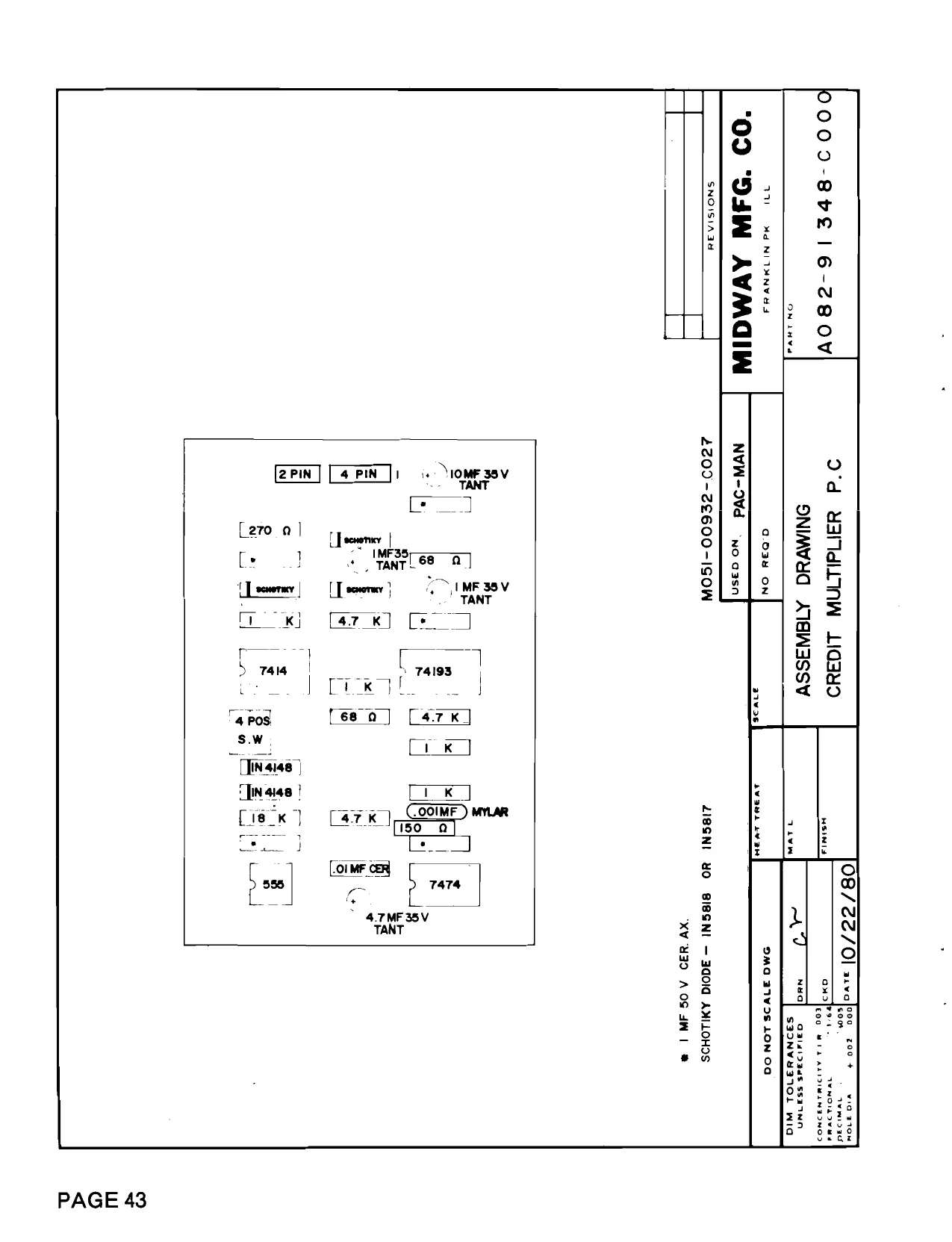
This page is a drawing, shown as the original scan.
AOS 4W I “xv Yad
AGE JW O!
FROM GAME 8D RESET LI ANWL ASE JWI
SCHOTIKY DIODE
2X INS8I8 ‘TO GAME 80 COIN INPUT ot OR IN58I7. SbloNI XZ ANVL AGE JW Lb
WS _NIOD “LIGBHOD 31d LINN MO5I-00932~C029 TEWaENS ETT PTET een _ PACT MAN MIDWAY MFG. CO. DO NOT SCALE OWG FRANKUINPK ILL
SCHEMATIC DIAGRAM
CREDIT MULTIPLIER A082 -91348 - C000
This page carries no recoverable text. It is a drawing or a photograph. See the original scan.
This page carries no recoverable text. It is a drawing or a photograph. See the original scan.
This page carries no recoverable text. It is a drawing or a photograph. See the original scan.
This page carries no recoverable text. It is a drawing or a photograph. See the original scan.
i ‘i
2scsiror 28c\lo6 28ciase 28ei633, 19" COLOR MONITOR SCHEMATIC DIAGRAM
INTERFACE BOARD P305
"80, Va, 8%
MAIN BOARD [MQ-29]
| vost | vosc | VEE. Fa ay DRIVE fag | OUT | AMP pscirao | |
| 254626 | 2501740 | zscirao | [Bl | 1749. | 1 |
| R30), | ZA | reso | 2SCTEO rp: | R104 | TR3OS 26490 TR307 |
| Ssaigiyasages | 308 zscrgs | R04 | scieIs | ties |
‘S80
820 10 pxoa®) 20201 20202 '
raz04 ra203 te208
| nen | rere | nays | |
| 33 | e | ey | |
| peek | Tao | Tom | Tm |
‘
reo? tao
+ + | ferric a "
| a | By | ascises | = | 1am 8968 | aw. 8% |
| = | PROTECTOR | Taso ROR OUT dt | a7 |
ee 7 ascigswescisaa/asciroR 2scin4o/ 25ci815_25a101s / 2saez6 Av
| dew opet i | 7 | ——__. «ss | ||
| STO | ane ote 4 | oPog | ad | cs |
7 ware oF, 160° (ave soar aS 5001" Tne ness
| 302 | dae | Bho 10 e60r@ | | |
es oan oe
| TaN, 10 econ | sant | — | = | = | S |
| RubIoT PORER | up our | sa? | t | ane |
om, AUD
| 8, | 7 | 5 | Cerigv. | Z |
| BOARD ERROR AMP {2 /4e | NECK poseo ME7G) Gl | lgvsTP22 | ||
| iar | reso: SCI7AOT ET Tao, | () | —— |
RT ass ecrme f* NG)... Fame] A ace 25n854/25a562 sarsuas
J rag THEY 5 ate
= cd 000877 ieavae we fe aE Ta raze Foo 600 a A oe oF Hovsy of | He, Seiten dia ee trees SERVICE TIP
DeGaussing ————-.- ‘con
25a608 25a826 25a854 esc i740 23crais 35Ke08
| ass | Ty | K4606- 5800 |
23a30 28ezeaz 6 ok
VERT/HOR BOARD (MT/QJ)
| Rel. No. | Part No. | Description | Ref. No. | Part No. | Description |
RESISTORS CAPACITORS (CONT.)
| R301 | 203X6500-628 | 820 Ohm, * 5%, 1/8W Carbon | 6313 | 203X0025-087 | 47 uF, 50V Electrolytic | |
| R302 | 203X6500-902 | 12k Ohm, * 5%, 1/8W Carbon | C315, | 203X0015-082 | 10 uF, 25V Electrolytic | |
| R303, | 203X6500.927 | 15k Ohm, * 5%, 1/8W Carbon | C316 | 203X1100-220 | 3300 uF, 50V, + 10% Mylar | |
| R304 | 203X6500-886 | 10k Ohm, = 5%, 1/8W Garbon | 317 | 202x8000-616 | 100 pF, 50V, = 10% Ceramic | |
| 305 | 203x6501-241 | 330k Ohm, + 5%, 1/8W Carbon | C354 | 202X7000-281 | 1500 pF, 50V, + 10% Ceramic | |
| R306 | 203X6500-645 | 1k Ohm, * 5%, 1/8W Carbon | 352 | 202X7000-247 | 1000 pF, 50V, + 10% Ceramic | |
| R307 | 203X6500689 | 1.5k Ohm, * 5%, 1/8W Carbon | 353 | 203X1100-573 | 0.022 uF, 50V, + 10% Mylar | |
| 303 | 203X6500-724 | 2.2k Ohm, * 5%, | 1/8W Carbon | C355 | 203X1100.858 | 0.1 uF, SOV, + 10% Mylar |
| R310 | 203X6501-285 | 470k Ohm, * | 5%, 1/8W Carbon | C356 | 203X0015-105 | 47 uF, 25V Electrolytic |
| R311 | 203X6501-065, | 56k Ohm, + 5%, 1/8W Carbon | C357 | 203X1201-013, | 0.015uF, 200V+ 10% PP | |
| R312 | 203X6501-126 | 100k Ohm, + 5%, 1/8W Carbon | 358 | 203K 1201-034 | 0.018 uF, 200V, = 10% PP | |
| R313 | 203x6001-326 | 10k Ohm, = 5%, 1/8W Carbon | 6359 | 203X0040-013 | 4.7 UF, 160V Electrolytic | |
| R314 | 203X6501-044 | 47k Ohm, + 5%, 1/8W Carbon | 360 | 202X7000-482 | 0.01 uF, 50V, | 10% Ceramic |
| R315 | 203X6500628 | 820 Ohm, + 5%, 1/8W Carbon | C361 | 203X1100-509 | 0.015 uF, 50V, + 10% Mylar | |
| R316 | 203X6500-420 | 120 Ohm, * 5%, 1/8W Carbon | C362 | 203X0025-058, | 10 UF, 50V Electrolytic | |
| 317 | 203X6206-441 | 2.2 Ohm, © 5%, 1/2W Carbon | C363 | 203X1205-487 | 0.07 UF, 630V, + 10% PP | |
| R319 | 203X6500-169, | 100 Ohm, + 5%, 1/8W Carbon | C364 | 202X7000-482 | 0.01 uF, 50V, * 10% Ceramic | |
| 320 | 203X6500-927, | 15k Ohm, = 5%, 1/8W Carbon | ||||
| R321 | 203X6700-508 | 560 Ohm, + 5%, 1/2W Carbon | ||||
| R322 | 203X9100-121 | 22 Ohm, + 5%, 2W MO. | SEMICONDUCTORS | |||
| 323 | 203X6500-689 | 1.5K Ohm, £5%, 1/8W Carbon | ||||
| R324 | 203X6500-988, | 27 Ohm, * 5%, 1/8W Carbon | R301 | 200X4082614 | Transistor, 2SA826Q | |
| R325 | 203X6500-326 | 47 Ohm, + 8%, 1/8W Carbon | TR302 | 200X3174-006 | Transistor, 25C17400 | |
| R328 | 203X6500-628 | 820 Ohm, + 5%, 1/8W Carbon | TR303, | 200X3174.006 | Transistor, 25A17400 | |
| F330 | 203X6500-886 | 10k Ohm, * 5%, 1/8W Carbon | TR304 | 200X3174-006 | Transistor, 28C17400 | |
| F331 | 203X6501-209 | 220k Ohm, * 5%, 1/8W Carbon | TR305, | 200X4049-081 | Transistor, 2SA490YLBGLI | |
| A351 | 203X6500-724 | 2.2k Ohm, = 5%, 1/8W Carbon | R308 | 200X3162.538 | Transistor, 25C1625YLBGLI | |
| A352 | 203X6500-927 | 15k Ohm, + 5%, 1/8W Carbon | R307 | 200X3174-014 | Transistor, 28C1740R | |
| F353 | 203X6500-944 | 48k Ohm, * 5%, | 1/8W Carbon | R308 | 200X3174-006 | Transistor, 2SC17400 |
| R354 | 203X6500-783 | 3.9k Ohm, + 5%, 1/8W Carbon | R351 | 200X4085-415, | Transistor, 2SA854Q | |
| A355, | 203x6500-902 | 12k Ohm, = 5%, ¥/8W Carbon | TR352 | 200X3172-208 | Transistor, 2SC1722BKS | |
| F386 | 203X6500-561 | 470 Ohm, * 5%, 1/8W Carbon | TRI53 | 200X3174.006 | Transistor, 28C17400 | |
| #357 | 203X6500-724 | 2.2k Ohm, + 5%, 1i8W Carbon | TR354 | 2004082614 | Transistor, 25A826Q | |
| F358 | 203X6500-666, | 1.2k Ohm, + 5%, 1/8W Carbon | X301 | 201X2010-144 | Diode, (SI) 182473-T72 | |
| A359 | 203X6501-088 | 68k Ohm, 2 5%, 1/8W Carbon | x302 | 201X2010-144 | Diode, (St) 182473-172 | |
| 360 | 203X5500-471 | 27 Ohm, + 5%, 1/4W Comp. | 303 | 200X8000-026 | Diode, (GE), INGOTVGL | |
| F361 | 203X6000-998, | 1.2k Ohm, * 5%, | 1/8W Carbon | x304 | 200X8010-165 | Diode (SI) 1SS81 |
| A363 | 203X6500-666 | 1.2k Ohm, + 5%, | 1/8W Carbon | 305 | 201X2010-165 | Diode (S!) 1SS81 |
| 364 | 203x9014-988 | 47k Ohm, = 5%, 1W M.O. | X306 | 201X2010-165 | Diode (SI) ISS81 | |
| R365, | 203X6700-989 | 56k Ohm, * 5%, 1/2W Carbon | x307 | 200X8010-102 | Diode (SI) MA26W | |
| R366 | 203X6001-148 | 3.3k Ohm, #5%, 1/8W Carbon | x308 | 200x8010-094 | Diode (St) 182473 | |
| A367 | 340X2222-734 | 2.2k Ohm, # 5%, 1/2W Carbon | x351 | 201X2010-144 | Diode (St) 1S2473-172 | |
| F368 | 203X6500-785 | 39k Ohm, = 5%, 1/8W Carbon | 362 | 201X2010-144 | Diode (SI) 182473-172 | |
| R369 | 203X6500-762 | 3.3k Ohm, * 5%, 1/4W Carbon | X353 | 201X2010-144 | Diode (St) 182473-T72 | |
| A370 | 302X6100-961 | 1k Ohm, + 5%, 1/4W Carbon | x354 | 201X2010-144 | Diode (SI) 1$2473-172 | |
| R371 | 203X6104-751 | 2.7k Ohm, * 5%, 1/4W Carbon | 355 | 200X8220-851 | Diode (Zener) RD10EBI | |
| R301 | 204x2122-093, | Varistor, 250K Ohm, Vert. Hold | 366 | 200X8100-130 | Diode (HS) RU-1 0.3 US | |
| R302 | 204x2114-065, | Varistor, 20K Ohm, Vert. Size | ||||
| VR351 | 204X2114-059 | Varistor, 50K Ohm, Hor. Hold |
MISCELLANEOUS
| CAPACITORS | 3301 | 204x9300-958 | Socket, 6 Pin | ||
| 15 uF, 50V, + 10% Mylar | 4302 | 204X9300-958 | Socket, 6 Pin | ||
| C02 | seoK 1100-873 | oa uF, 50V, + 10% Myler | P301 | 204X9601-195 | Plug, 6 Pin |
| 304 | 203X1100-858 | 0.1 uF, 50V, + 10% Mylar | P302 | 204X9601-195 | Plug, 6 Pin |
| C306 | 203X0025-026 | 22 uF, 50V, Electrolytic | TH301 | 201x0000-634 | Thermistor |
| 307 | 203X1100-928 | 0.15 uF, 50V, + 10% Mylar | |||
| C309 | 203X1100-858 | 0.1 uF, 50V, + 10% Myler | |||
| 310 | 203X0010-011 | 22 uf, 16V Electrolytic | TRANSFORMERS & COILS | ||
| e314 | 203X0020-089 | 1000 uF, 35V Electrolytic | |||
| e312 | 202X7000-469 | 0.0082 uF, 50V, + 10% Ceramic | 3st | 201x5200-081 | Colt, Horiz. Osc. |
POWER BOARD (MV)
| 503 | 203x0010-011 | 22 uF, 16V Electrolytic | |
| RESISTORS | C551 | 203X0005-046 | 220 uF, 10V Electrolytic |
| sos | 204Xx1725-052 | 180 Ohm, + 10%, 15W WW |
203X6000-608 100 Ohm, * 5%, 1/8W Carbon Si TOR
| R503 | 203X6000-960 | 1k Ohm, = 5%, 1/8W Carbon | EMICONDUCTORS | ||
| R504 | 203x6000-879 | 560 Ohm, * 5%, 1/8W Carbon | TRSO1 | 200x3174-006 | Transistor, 28617400 |
| A505, | 203x9014-965, | 39k Ohm, + 5%, 1W M.O. | Ax TR502 | 200X3145-404 | Transistor, 2501454 |
| F506 | 203X6500-842 | 68k Ohm, + 5%, 1/8W Carbon | TR5S1 | 200X3172-305 | Transistor, 25C1723 |
| R551 | 203X6500-420 | 120 Ohm, = 5%, 1/8W Carbon | x501 | 201X2230-042 | Diode, (St) Zener EQB01-06V |
| VASO1 | 204X2050-001 | Varistor Vert. Adj. | x502 | 201X2010-144 | Diode, (S!) $2473.72 |
CAPACITORS MISCELLANEOUS
| 501 | 203x0040-020 | 10 uF, 160V Electrolytic | J501 | 204X9300-958 | Socket, 6 Pin |
| C502 | 202X7000-281 | 1500 pF, 50V, + 10% Ceramic | P501 | 204X9601-195 | Plug, 6 Pin |
| THSO1 | 201X0000-618 | Thermistor |
NECK BOARD (MS/QG)
| Ret, No. | Part No. | Description | Ref. No. | Part No. | Description |
RESISTORS
| R401 | 203X6500-709 | 1.8k Ohm + 5% 1/8W Carbon | ey | ||||
| Ragz | 203X6500-709 | 118k Ohm # 5% 1/BW Carbon | ond | 202X7000-247 | 1000 pF, 50V, 10% Ceramic | ||
| R403 | 203X6500-709 | 1.8k Ohm + 5% 1/8W Carbon | oa | 202Xx7110-019 | 1500 pF, 2kV' x 10% Ceramic | ||
| R404 | 203X6500-447 | 150 Ohm + 5% 1/8W Carbon | C405 | 202X7150-018 | 100 pF, 12kV, + 10% Ceramic | ||
| R405 | 203X6500-481 | 220 Ohm # 8% 1BW Catoon | C408 | 202X7050-483, | .01 uF, 500V,’ « 10% Ceramic | ||
| Ra06 | 203X6500-447 | 150 Ohm + 5% | VBW Carbon | C407 | 202X7110-019 | 1500 pF, 2kV | 10% Ceramic |
| R407 | 203X6500-508 | 270 Ohm + 5% 1/8W | bon | C408 | 202X8000-550 | 68 pF, 50V, + 10% Ceramic | |
| R408 | 203X6500-508 | 270 Ohm + 5% 1/8W Carbon | Ga09 | 202x8000-550 | 68 pF, SOV, + 10% Ceramic | ||
| Raog | 203X6500-00 | 47k Ohm + 5% 1/8W Carbon | cat0 | 202x8000-550 | 68 pF, SOV, = 10% Ceramic | ||
| R410 | 203X6500-800 | 47k Ohm + 5% 1/8W Carbon | |||||
| Rat? | 203X6500-800 | 4.7k Ohm * 5% 1/8W Carbon | |||||
| R412 | 203X9104-809 | 12k Ohm + 5% 2.0W Meial Oxide | |||||
| R413 | 203X9104-809 | 12k Ohm + 5% 2.0W Metal Oxide | SEMICONDUCTORS | ||||
| Raid | 203X9104-809 | 12k Ohm + 5% 2.0W Metal Oxide | |||||
| Rais | 203X5607-313 | 2.7k Ohm + 1 | V2w Comp. | TR401 | 200X3206-800 | Transistor, 25C2068, 2SC1514 | |
| R416 | Pad | oe oem = we aw Som. | (R output) | ||||
| RAI7 | 203X5601-3 | 7k OhM + 10% 12W Comp. | TR402 | 200X3206-800 | Tra | 1 | |
| Ra18 | 200x860 254 | 470k Ohm = 10% 1r2W Comp. | aa | ||||
| R419 | 203) | 12-185 | 330k | Ohm + 10% 1/2W | Comp. | ||
| R422 | 203X9105-117 | 4.0 Ohm | 10% 2W Metal Oxide | "R408 | 200X3206-800 | Tyonsistor, 2562068, 2501514 | |
| R423 | 203X5 102-155. | 270k Ohm + 5% 1/4W Carbon | . | ||||
| R401 | 204x2115-014 | 500 Ohm Varistor R Drive | ae | BOUX2 100-126 | Biode,.152967 (proiecton | ||
| vR402 | 204X2115-014 | 500 Ohm Varistor B Drive | 408 | 20 pearcered | Diode, 182367 (protector) | ||
| vR403 | 204X2115-008 | 5k Ohm Varistor R Cutoft | x | 201X2100-126 | Diode, 182367 (protector) | ||
| VR404 | 204X2115-006 | 5k Ohm Varistor G Cutoff | |||||
| VRA05 | 208X2115.006 | 5k Ohm varistor B Cutoft | |||||
| VR406, | 204X2000-025 | 1M Ohm | Varist |
sciciiaiiee MISCELLANEOUS
| CAPACITORS | 401 | 208X5003-729 | Socket, 5 Pin | ||
| 9402 | 206X5003-983, | Socket, 3 Pin | |||
| cao1 | 202X7000-247 | 1000 pF, 50V, 10% Ceramic | P401 | 204X9600-329 | Plug, 5 Pin |
| 402 | 202X7000-247 | 1000 pF, 50V, 10% Ceramic | P402 | 204X9600-254 | Plug, 3 Pin |
4x 297X2000-072 HIGH VOLTAGE ASSEMBLY (1701) FINAL ASSEMBLY PARTS
| Ak A701 | 204X 1625-058 | 3.3 Ohm, + 10% 10W WW Resistor | A | 88X.0120-506 | 19VJTP22 Pix Tube |
| VR702 | 204X3901-125 | Focus Control | 38A5554-000 | Assy. Purity Shid/Degaussing | |
| x701 | Diode (S! HV) | 205x9800-256 | Lateral/Purity Assembly | ||
| X702 | Diode (St HV) | Part of T701 | Ak 202X1110-810 | Yoke, Deflection | |
| x703 | Diode (SI HV) | 208X2000-946 | CRT Socket |
2972000-072 HV Unit (1701)
6A0397 Plug, Line Cord
9A2753-003 Degaussing Coil (L701)
INTERFACE BOARD (P305)
(MODEL 19K 4606)
RESISTORS SEMICONDUCTORS
| R201 | 340X3910-934 | 91 Ohm, 5%, 1/2W Carbon | TR201 | 86X0121-001 | Transistor (NPN) | |
| R203 | 340X3102-034 | 1/2 Carbon | TR202 | 86X0121-001 | Transistor (NPN) | |
| R204 | 340X2101-934 | 4/4W Carbon | TR203 | 86X0121-001 | Transistor (NPN) | |
| R206 | 340X3331-944 | 330 Ohm, 10%, | 1/2W Carbon | TR204 | 86X0066-001 | Transistor (PNP) |
| R207 | 340X3102-934 | 1k Ohm, 5%, 1/2W Carbon | TR205 | 86X0066-001 | ‘Transistor (PNP) | |
| R208 | 340X3152-934 | 1.5k Ohm, 5%, 1/4W Carbon | TR206 | ‘86X0066-001 | Transistor (PNP) | |
| R209 | 340X2101-934 | ‘V4w Carbon | ‘TR207 | 86X0121-001 | Tr | istor (NNP) |
| R210 | 340X3102-934 | ‘12 Carbon | 7R208 | 86X0121-001 | Transistor (NPN) | |
| R21 | 340X2331-934 | 1/4W Carbon | ‘TR209 | 86X0121-001 | Transistor (NPN) | |
| R212 | 340X2331-934 | 330 Ohm, 5%, 1/4W Carbon | ZD201 | 66X0040018 | Diode, Zener, 6.8v, 5%, 0.5W | |
| R213 | 340X2331-934 | 330 Ohm, 5%, 1/4W Carbon | 20202 | 66X0040-019 | Diode, Zener, 3.9v, 5%, 0.5W | |
| R214 | 340X2201-834 | 200 Ohm, 5%, | VW Carbon | |||
| R215 | 340X2201-934 | 200 Ohm, 5%, 1/44W Carbon | ||||
| R216 | 340X2201-934 | 200 Ohm, 5%, 1/4W Carbon | MISCELLANEOUS | |||
| ‘R201 | 40X0590-017 | 1.5k Ohm, Black Level Control | ||||
| J201 | 204X9300-958 | Socket, 6 Pin | ||||
| $202 | 204X9300-958 | Socket, 6 Pin | ||||
| CAPACITORS | J203, | 206X5019-207 | Socket, 4 Pin | |||
| P201 | 204X9601-195, | Plug, 6 Pin | ||||
| C201 | 45X0524-038 | 1000 uF, 16V Electrolytic | P02 | 204X9601-195 | Plug, 6 Pin | |
| P203 | 204X9600-845, | Plug, 4 Pin | ||||
| P205 | 6A0393-006 | Plug, 6 Pin |
WELLS—GARDNER INSTALLATION AND SERVICE INSTRUCTIONS
COLOR PURITY AND VERTICAL CENTERING ADJUSTMENT
For best results, it is recommended that the purity adjustment be made in the final monitor location. If the monitor wili be moved, perform this adjustment with it facing west or east. The monitor must have been operating 15 minutes prior to this procedure and the faceplate of the CRT must be at room temperature. The monitor is equipped with an automatic degaussing circuit. However, if the CRT shadow mask has become excessively magnetized, it may be necessary to degauss it with manual coil. Do not switch the coil OFF while the raster shows any effect from the coil. Purity Magnets are used for Color Purity and V Centering Adjustment. Purity Adjustment procedure is as follows.
- Remove R-G-B signal from monitor.
- Turn Green Cut off Control! (VR404) on the Neck Board fully CCW. Turn Red and Blue Cut off Control (VR405) fully CW.
- Pull the Deflection Yoke backward so that the Magenta belt will appear. (See Fig. 4)
- Move the two Purity Magnets and bring the Magenta belt to the mechanical center of the screen (See Fig.
- The vertical center position should be set VRS to —5/64” (—2 mm) as shown in Fig. 6. Insert service tip “N” on Neck circuit board to “S” on Vert./Horiz. circuit board (See Fig. 13). To check, use the Green raster at low intensity. Be sure to return the service tips to their original positions for the next check.
- Push the Deflection Yoke forward gradually and fix it at the place where the Magenta screen becomes uniform throughout.
- Turn Cut off Control, and Drive Control and confirm that each color is uniform.
- If the color is not uniform, re-adjust it moving Purity Magnets slightly.
- Move a pair of Purity Magnets at the same time (do not change the angle of the pair), and adjust the vert. center to center of screen.
- Obtain the three colors and confirm whether white uniformity is balanced.
- Insert the temporary wedge as shown in Fig. 5 and adjust the angle of Deflection Yoke.
STATIC CONVERGENCE ADJUSTMENT
A recently developed Deflection Yoke and Electron Guns construction has been used on this equipment in combination with In-Line Guns and Black Stripe Screen to make a barrel-type magnetic-field distribution for vertical deflection and a pin-cushion-type magnetic field for horizontal deflection with which a_ self-converging system can be obtained. This type is different from conventional unity-magnetic field distribution type deflection yoke. 4-Pole Magnets and 6-Pole Magnets are employed for static convergence instead of a Convergence Yoke.
- A cross hatch signal should be connected to the monitor.
- A pair of 4-Pole Convergence Magnets are provided and adjusted to converge the blue and red beams. When the Pole opens to the left and right 45° symmetrically, the magnetic field maximizes. Red and blue beams move to the left and right oppositely (See Fig. 7-a and 7-b). Variation of the angle between the tabs adjusts the convergence of red and blue vertical lines. When the both 4-Pole Convergence Magnet Tabs are rotated as a pair, the convergence of the red and blue horizontal lines is adjusted.
- A pair of 6-Pole Convergence Magnets are also provided and adjusted to converge the magenta (red + blue) to green beams. When the Pole opens to the left and right 30° symmetrically, the magnetic field is maximized. Red and blue beams both move to the left and right (See Fig. 8c and 8-d). Variation of the opening angle adjusts the convergence of magenta to green vertical lines. When both 6-Pole Convergence Magnet Tabs are rotated as a pair the convergence of magenta to green horizontal lines is adjusted.
PRECISE ADJUSTMENT OF DYNAMIC CONVERGENCE (See Fig. 10 and 11)
- Feed a cross hatch signal to the monitor.
- Insert the temporary wedge and fix Deflection Yoke So as to obtain the best circumference convergence (See Fig. 10 and 11).
- Insert three rubber wedges to the position as shown in Fig. 9 to obtain the best circumference convergence.
- Tilting the angle of the yoke up and down adjusts the crossover of both vertical and horizontal red and blue lines. See Fig. 10 (a) and (b).
- Tilting the angle of the yoke sideways adjusts the parallel convergence of both horizontal and vertical lines at the edges of the screen. See Fig. 11-a and b.
- Use three rubber wedges (thick and thin rubber wedges are used for a purpose).
- The angle of each rubber wedges are shown in Fig. 9.
- After three rubber wedges have been inserted, pull out the temporary wedge.
- Fix the rubber wedges with chloroprene rubber adhesive.
INSTALLATION AND SERVICE INSTRUCTIONS
BLACK AND WHITE TRACKING (cow.
| (With R/G.B. inputs grounded) | 4. | Slowly turn up G2 screen control until the first faint |
color appears.
| 1. | Set Black Level Control (VR201) to mid point. | 5. | Slowly turn up the other two color cut-off controls in |
| 2. | Set Red and Blue Drive Controls (VR401 & VR402) to | turn to match the first. | |
| their mechanical center. | 6. | Remove ground from R/G/B/ inputs. Adjust Red and | |
| 3. | Set the G2 Screen Control (VR406) and the 3 Cut-off | Blue Drive Controls (VR401 & VR402) for white |
Controls (VR403, VR404, & VR405) to minimum screen.
Temporary Wedge
_— Mecha crt oy [ Le + vas nel — 5/64" Green Beam TT ial
FIGURE 4 FIGURES FIGURE 6
4-Pole Magnets and the Movement of Beams
FIGURE 7 6-Pole Magnets and the Movement of Beams
FIGURES
INSTALLATION AND SERVICE INSTRUCTIONS
BGR
R a G G B R
RGB
CRT Screen a
aloe
(ah CRT Screen Temporary Wedge
Deflection Yoke
FIGURE 9
Upper RGB
8 R cRT G G R 8
Under BGR
(o Insert Rubber Wedge CRT Screen from Upper Side
FIGURE 10
(b) Insert Rubber Wedge CRT Screen from Left Side
FIGURE 11 Upper
CRT
yp
Under
Insert Rubber Wedge from Lower Side
CRT
YC
Insert Rubber Wedge from Lower Side a
INSTALLATION AND SERVICE INSTRUCTIONS
VR406 Screen
VR403 Red Cut Off
VR404 Green Cut Off
VR405 Blue Cut Off
VERT./HORIZ. BOARD [MT/QJ| NECK BOARD[MS/QG
FIGURE 12
——— ANODE CONTACT
25" (67.5 mm) =
6 POLE CONVERGENCE MAGNETS
- 4 POLE CONVERGENCE MAGNETS ~~ PURITY CENTERING MAGNETS
~———— DEFLECTION YOKE
RUBBER WEDGES CONVERGENCE MAGNET ASS'y
FIGURE 13, PICTURE TUBE NECK COMPONENTS LOCATION
‘Alug ontex RED XI01.X103 and XIO5 VIDEO AMP, 2SC454C x102.X104 and XI06 VIDEO AMP. 2SA673C G8 VIDEO OUTPUT, Tor 28cisi4v ES
1x301,x302,x808,x808 SYNC AMP faScas4c or esciees weearwensme Qh | Ex
ween ve ate J[xs03 weaw uniter 250673 pi [x04 BLANKING Bax | 28casac orztcicer oo
X901 POWER DRIVE 25C 2686 3 X 902 ERROR AMP —2SC1890 I ¥e 81 x08 | 28cii96a, 2sciasa . POWER REGULATOR vr 3 ISU-3032A | cRT SocKET pep assy | trom suas]
2888 Jraic c ve cue, Te hie soc rm aba
i Schematic Notes f.13) Ei E wh aa Unless otherwise specified Ncouy Ate * tk Resistance: (Q) (K*KQ, M+MQ,), 1/4 (W) carbon resistor tae te abe Capacitance: 1 or higher» (pF), less than 1-> (yF) fis ea By working voltage ~» 50 (V) L 13a te i ceramic capacitor pi Inductance: (H) BEG ction YOKE Electrolytic Cap: Capacitance Value YF) /working voltage (V), 88a aro NP - non-polar (or bipolar) electrolytic cap. SU-1133A. ae | Refer to the parts list for additional component information. MAIN BGP B22 _ ——_ —__— —s oO —_— 2 indicates test point connection 7 X50) HORI er cnt weaten weekdse e ascieae. 29ciso7 ‘BS, zscesr eapees ne eurtazen indicates chassis ground unless otherwise specified loo] 4 280820 ACI20V 6OH2/50H2 10% Hz _ indicates cycles per second For safety purposes (and continuing reliability) aA replace all components marked with safety syrnbol with identical type.
00-4147-04 Parts identification on circuit boards:
G07-CBO e.g. SU1126A (R107 = R1107) SU3030A (R113 = R3113)
REPLACEMENT PARTS LIST - ELECTROHOME 19”? MONITOR
special characteristics important to safety. Components identified by the A symbol in the PARTS LIST and on the Schematic have
DO NOT degrade the safety of the set through improper servicing.
Abbreviations for Resistors and Capacitors
Resistor Capacitor
| CR | : Carbon Resistor | C Cap. |
| Comp. R | : Composition Resistor | M Cap |
| OMR | : Oxide Metal Film Resistor | E Cap. |
| VR | : Variable Resistor | BP E Cap. |
MF R : Metal Film Resistor
| CMF R | : Coating Metal Film Resistor | MM Cap. |
| UNF R | : Nonflammable Resistor | PP Cap. |
| FR | : Fusible Resistor | MPP Cap. |
PS Cap Tan. Cap. : Ceramic Capacitor Mylar Capacitor Electrolytic Capacitor Bi-Polar (or Non-Polar) Electrolytic Capacitor Metalized Mylar Capacitor Polypropylene Capacitor Metalized PP Capacitor Polystyrol Capacitor : Tantal Capacitor
SERVICE REPLACEMENT PARTS LIST
Symbol Description
Main P.C.B. Ass'y CRT Socket P.C.B. Ass'y Purity Shield Ass'y Part Number SU-1133A SU-3032A 07-220083-03
Outside of the P.C.B. Ass’y Symbol Description Picture Tube 19” A AXDeflection Yoke PC Magnet A A\Flyback Transf. A AHVR ROS UNF Resistor 22092.,25W K C04 C Capacitor 150pF, AC1.5KV x01 Si. Transistor x02 Si. Transistor sc Screw #8-% SC Screw % x % Pix Tube Mtg. (4) WA Pyramidal Lock Washer (4) Nut Retainer, Pix Tube Mtg. (4) Clip — P.C.B. Support Standoff Wire Terminal (Gnd. Strap) Terminal Lug (Gnd.) Groundstrap Assy. Grounding Spring Wire Hook (Gnd. Strap) Purity Shield Holddown Clamp Support Brkt. RH Support Brkt. LH Chassis Base Yoke Wedge (3)
Purity Shield Ass’y. Parts List
Symbol Description Degaussing Coil 0911, 0912 Rectifier 1 Amp 600V (2) Pin Terminal (2) Pin Terminal Housing Purity Shield (2 pcs.) Purity Shield (2 pes.) cot Capacitor 100nF 10% 400V R921 Resistor, Wirewound 339, 4W Fire Retardent Term. Strip 4 Lug
CRT Socket P.C.B. Ass'y (SU-3032A) Parts List
Resistors Symbol! Description
| 3105 | v | R 200 |
| R3106 | v | R 200 |
| R3113 | Vv | R SK |
| R114 | Vv | R 5K |
| R3115 | Vv | R 5K |
| R3116 | OM | R iKQAW J |
| R3117 | OM | R 10K Q2W J |
| R3118 | OM | R 10KQ2W J |
R3119 Comp. R 3.3KQ”%WK R3120 Comp. R 3.3K2%W K 3121 Comp. R 3.3KQ’%W K
Capacitors Symbol Description C3107 E Cap. 10uF 250V A C3108 C Cap. 1000pF DC1400V P
Coils Symbol Description 13101 Peaking Coil Part Number 17-7 198-03 A29779-D = 21-141-01 A75034-B = 29-32-01 A29951-B A46600-A QRF258K-221 QCZ0101-005 2SD870 2S8C1106A 31-610818-06 31-601418-12 33-255-01 33-494-01 33-629-02 33-670-010R-02 34-228-03 34-33-04 34-574-02 35-212-03 35-3053-02 35-2348-01 35-3890-01 35-3890-02 38-449-02 39-1233-01
Part Number 21-1007-30 28-22-27 34-708-01 34-709-01 35-3847-01 35-3847-02 48-171544-62 42-113301-03 34-492-09
Part-Number QVZ3234-022 QVZ3234-022 QVZ3234-053 QVZ3234-053 QVZ3234-053 QRG029J-103 QRGO29J-103 QRG029J-103 QRZ0039-332 QRZ0039-332 QRZ0039-332
Part Number QEW53EA-106 QCZ9001-102M
Part Number QQL043K-101
Semiconductors Symbol X3101 X3102 X3103
Miscellaneous Symbol A Description Si. Transistor Si. Transistor Si. Transistor
Description AXCRT Socket
Main PCB Ass'y (SU-1133A) Parts List
Resistors Symbol R1406 R1408 R1410 R1414 R1415 R1421 R1422 AFR1401 AA1503 R1504 R1509 R1512 R1514 R1515, R1522 R1523 R1528 R1534 VR1501 AR1703 ASR1704 A\R1901 R1902 R1903 R1904 R1905 4Q1908 ASR1909 R1910 ASFR1901
Capacitors Symbol C1301 C1402 C1407 c1411 C1412 C1508 Ac1512 AC1513 AC1514 C1515 C1520 C1523 C1524 AC1531 201532 C1904 C1905, Vv CMF om OM OM v AF A\CMF v om om om CMF CMF OM om ZN ZN A\CMF A\CMF A’Posistor UNF CMF OM OM ZAXCMF Vv AXCMF AF DDVDVVVVDD DHDVVVVVVVVVUDVVDVUDDIVD Description Vv 2002 2002 6.8Q1W J 3.3KQ1W J 2.7K Q1W J 12KQ.2W J 10KQ 6822W K 11.8KQ. “AW +1% 5KQ. 10KQ2W J 8.2KQ2W J 82022W J 8.201W J 4.7Q1W J 6822W J 39021W J
39N2W +1% 7.68KQ. YaW +1%
227W K 4.703W J 10KQ2W J 18KQ1W J 47 QW +1% 2KQ 2.74K QW 41% 2202%W K
Description BPE Tan. E E E PP APP App App PP BPE E M APP APP E E Cap. Cap. Cap. Cap. Cap. Cap. Cap. Cap. 3.3uF 50V A 2.2uF 16V K 4.7uF 6.3V A 100uF 160V A 3.3uF 160V A 5600uF SOV J 2000pF DC1500V J 2000pF DC1500v J . 2000pF DC1500V J . 0.53uF DC1200V J . 3.3uF 50V A . 1UuF 160V A . 0.1UF 200V K . 2000pF DC1500V J . 1500pF DC1500V J
. 10UF 250V A Part Number 2SC1514VC 28C1514VC 2SC1514VC
Part Number A76068
Part Number QVZ3230-002 QVZ3230-002 QRX019J-6R8 QRG019J-332 QRG019J-272 QRGO26J-123Z QVZ3230-014 QRH024K-680M QRV142F-1182 QVZ3230-053 QRGO26J-103Z QRG026J-822Z QRG026J-821Z QRX019J-8R2 QRX019J-4R7 QRGO26J-680Z QRGO19J-391 ERZ-C05ZK471 ERZ-C05DK271 QRV122F-3902 QRV142F-7681 A75414 QRFO76K-2RO QRX039J-4R7 QRGO26J-103Z QRGO19J-183 QRV122F-470Z QVPS5A0B-023E QRVi42F-2741 QRH124K-221M
Part Number QEN61HA-335Z QEES1CK-225B QEWS1JA-475, QEWS2CA-107 QEW52CA-335 QFP31HJ-562 QFZ0082-202 QFZ0082-202 QFZ0082-202 QFZ0067-534 QEN61HA-335Z QEW62CA-105Z QFM720K-104M QFZ0082-202 QFZ0082-152 QEY0034-001 QEWS2EA-106
Semiconductors
Symbol Description
X3101 Si. Transistor X3102 Si. Transistor X3103 Si. Transistor
Miscellaneous
A ACRT Socket
Main PCB Ass’y (SU-1133A) Parts List
Resistors
| R1406 | v | R 2002 |
| R1408 | Vv | R 2002 |
| R1410 | CMF | R 6891WJ |
R1414 OM = R 33KQ1WJ
| R1415 | OM | R 27KQIWJ |
R1421 OM = R 12K22WJ
| R1422 | v | R 10K |
| AFR1401 | AF | R 6822w K |
| AR1503 | ACMF | R11.8KQUW +1% |
| R1504 | Vv | R 5SkQ |
| R1509 | OM | = R 10KQ2WJ |
| R1512 | OM | R 8.2KQ2W J |
| R1514 | OM | =R 82022W J |
| R1515 | CMF | R 8.291WJ |
| R1522 | CMF | R 4.721WJ |
| R1523 | OM | R 6822W J |
| R1528 | OM | R 39021WJ |
| R1534 | ZN | OR |
| VR1501 | ZN | OR |
| AR1703 | ACMF | RR 3922%4W +1% |
| ASR1704 | ACMF | R_7.68KQ.AW +1% |
4R1901 AsPosistor
| R1902 | UNF | R 2Q7WK |
| R1903 | CMF | OR 4.723W J |
| R1904 | OM | R 10KQ2WJ |
R1905 OM = R 18KQ1IWJ
| AQQ1908 | ACMF | R 472.%W+1% |
| AR1909 | v | R 2kQ |
| R1910 | ACMF | RR 2.74KQYW+1% |
| ASFR1901 | AF | R 2200%W K |
Capacitors
C1301 BPE Cap. 3.3uF 50V A C1402 Tan. Cap. 2.2uF 16V K
| C1407 | E | Cap. 4.7uF 6.3V A |
| C1411 | E | Cap, 100uF 160V A |
| C1412 | E | Cap. 3.3uF 160V A |
C1508 PP Cap. 5600uF 50V J Ac1512 APP Cap. 2000pF DC1500V J AC1513 APP Cap. 2000pF DC1500V J AC1514 APP Cap. 2000pF DC1500V J C1515 PP Cap. 0.53uF DC1200V J 1520 BPE Cap. 3.3uF 50V A
| 1523 | E | Cap. 1uF 160V A |
| 1524 | M_— | Cap. 0.1uF 200V K |
AC1531 APP Cap. 2000pF DC1500V J 2C1532 A\PP_ Cap. 1500pF DC1500V J
| C1904 | E | Cap. |
| 1905 | = | Cap. 10uF 250V A |
Part Number 2SC1514VC 2SC1514VC 2S8C1514VC
Part Number A76068
Part Number QVZ3230-002 QVZ3230-002 QRX019J-6R8 QRGO019J-332 QRG019J-272 QRG026J-123Z QVZ3230-014 QRH024K-680M QRV142F-1182 QVZ3230-053 QRG026J-103Z QRG026J-822Z QRG026J-821Z QRX019J-8R2 QRX019J-4R7 QRG026J-680Z QRG019J-391 ERZ-C05ZK471 ERZ-COSDK271 QRV122F-3902 QRV142F-7681 AT5414 QRFO76K-2RO QRX039J-4R7 QRG026J-103Z QRG019J-183 QRV122F-470Z QVPSA0B-023E QRV142F-274) QRH124K-221M
Part Number QEN61HA-335Z QEES1CK-225B QEWS1JA-475 QEW52CA-107 QEWS52CA-335, QFP31HJ-562 QFZ0082-202 QFZ0082-202 “ QFZ0082-202 QFZ0067-534 QEN61HA-335Z QEW62CA-105Z QFM720K-104M QFZ0082-202 QFZ0082-152 QEY0034-001 QEWS2EA-106
SED GREEW GLUE XIOI.XIO3 ond XI0S VIDEO AMR, 2SC454C oy 25c 1685. X102.X104 ond Xi06 VIDEO AMP 25A673C — oo ‘xi03 RoEB VIDEO OUTPUT x, Bsezelr or BEsiav Blu
= |SU-3016A | CRT SOCKET pee assy | X301,x302,X305, x306 SYNC AMP) [25c454C or 2sci6es
nec nee nme mad} | Bee
| x303 BEAM LIMITER 258673 pe | xg0a BLANKING 2acasac eoa tie v sre 60.
[ Icol POWER REGULATOR - STRIB3 SU-I103A MAIN PCB ASSY Jt
FBCv oui on
Seoltov wr tts * air Pun Schematic Notes vite Unless otherwise specified E Resistance: (Q.) (K-*KQ, M-MQ), 1/4 (W) carbon resistor Capacitance: 1 or higher-» (pF), less than 1-> (yF) BEPLecmion vore working voltage —> 50 (V) ceramic capacitor Inductance: (v H) Electrolytic Cap: Capacitance Value ( F)/working voltage (V), NP — non-polar (or bipolar) electrolytic cap. X7Ol X-RAY PROTECTOR x50! HOR UT 8 or 25CI 28tis07 WE, escosrw 280098 or 4 aH . ‘BSCASAC ‘or 256 1085; 28C26II or ZC26ioBK 250869 Refer to the parts list for additional component information. g indicates test point connection oh indicates chassis ground unless otherwise specified ACI20V 6OHE/SOHE slo
Hz _ indicates cycles per second For safety purposes (and continuing reliability) A replace all components marked with safety symbol with identical type.
G07-FBO 00-4147-03 Parts identification on circuit boards: e.g. SU1126A (R107 = R1107) SU3030A (R113 = R3113)
REPLACEMENT PARTS LIST - ELECTROHOME 13’? MONITOR
Components identified by the AV symbol in the PARTS LIST and on the Schematic have special characteristics important to safety. DO NOT degrade the safety of the set through improper servicing.
Abbreviations for Resistors and Capacitors
Resistor Capacitor
| CR | : Carbon Resistor | C Cap. |
| Comp. R | : Composition Resistor | M Cap |
| OM R | : Oxide Metal Film Resistor | E Cap. |
| VR | : Variable Resistor | BP E Cap. |
MFR : Metal Film Resistor
| CMF R | : Coating Metal Film Resistor | MM Cap. |
UNF R Nonflammable Resistor PP Cap.
| FR | : Fusibie Resistor | MPP Cap. |
PS Cap Tan. Cap. Ceramic Capacitor Mylar Capacitor Electrolytic Capacitor Bi-Polar (or Non-Polar) Electrolytic Capacitor Metalized Mylar Capacitor Polypropylene Capacitor Metalized PP Capacitor Polystyrol Capacitor Tantal Capacitor
Symbol
Outside of the P.C.B. Ass'y Symbol Avo1 ApyY01
Arn AROS ASco4 x01 1c01
BR BR sc WA
CH Description Main P.C.B. Ass'y CRT Socket P.C.B. Ass'y
Description AsPicture Tube AXDeflection Yoke PC Magnet Wedge AsFlyback Transf. AFocus V R UNF Resistor 2202, 25W. K AC Capacitor 150 pF, AC1.5KV Si. Transistor IC Regulator Degausing Coil Degausing Coil Pin Terminal (2) Degausing Coil Pin Terminal Housing Groundstrap Ass’y. Groundstrap Wire Terminal Groundstrap Spring (2) Support Bracket RH Support Bracket LH SCREW 10-% Pix Tube Mtg. (4) Pyramidal Lockwasher (4) Clip P.C.B. Support (2) Ground Lug Chassis Base Part Number SU-1103A SU-3016A
Part Number 370ESB22(E) C29123-V A76366-A 30006 A19183-A A46606-A QRF258K-221 QCZ0101-005 2SD869 STR383 21-1007-31 34-708-01 34-709-01 34-697-04 34-228-03 35-3560-01 35-3919-01 35-3919-02 31-631018-08 33-255-01 33-629-02 34-33-04 38-452-01
Main P.C.B. Ass'y (SU-1103A) Parts List
Resistors Symbol R1406 R1408 R1410 R414 R145 R1421 R1422 AXFR1401 A\R1503 R1504 1509 R1511 R1514 R1515 R1522 R1523 R1528 R1534 VR1501 ASR1703 A\R1704 A\R1901 R1902 R1903 R1904 AXFR1901
Capacitors Symbol C1402 c1411 C1412 C1508 C1811 Acts12 AC1513 AC1514 C1515 1520 C1524 1904 C1905 A\c1907
Coils Symbol 11501 L1502 L1503 L1504 £1901
Transformers Symbol T1501 T1503 Description v Vv R R CMF R om om om v AF R R R R R ACMF R Vv OM OM OM R R R R CMF R CMF R OM OM ZN ZN R R R R ACMF R AXCMF R 7.68KQ YW +1% A’Posistor UNF R 227WK CMF R 5.623W J OM R 10KQ2W J AF R 2002 2002 6.821W J 3.3KQ1W J 27KQ1W J 12KQ2W J 10KQ. 6822W K 11.8KQ“W +1% 5KQ. 10KQ2W J 5.6KQ2W J 6802 2W J 8.2 O1W J 4721W J 5622W J 39021W J
39KQUW +1%
2202 2W K
Description Tan. E E PP E APP APP AXPP PP
M E E AMM Cap. Cap. . 3.3uF 160V A
Cap. BPE Cap. Cap. 2.2uF 16V K 100uF 180V A
. S6O0OpF SOV J . 47uF 160V A . 2000pF DC1500V J . 2000pF DC1500V J . 2500pF DC1500V J 0.53uF DC1200V K 1uF 50V A 0.1uF 200V K Cap. Cap. Cap. 10uF 250V A O.1uF AC150V Z
Description Peaking Coil Liniarty Coil Width Coil Heater Choke Line Filter
Description Hor. Drive Transf. Side Pin Transf. Part Number QVz3230-022 QVZ3230-022 QRX019J-6R8 QRGO19J-332 QRGO19J-272 QRGO29J-123 QVZ3224-014H QRHO024K-680M QRV142F-1182 QVZ3230-053 QRG029J-103 QRGO029J-562 QRG029J-681 QRX019J-8R2 QRX019J-4R7 ORG029J-560 ORGO19J-391 ERZ-C05ZK471 ERZ-COSDK271 QRV122F-3902 QRV142F-7681 A75414 QRFO76K-2RO QRX039J-5R6 QRGO26S-103Z QRH124K-221M
Part Number
QEES1CK-225B QEWS2CA-107 QEW52CA-335 QFP31HJ-562 QEW52CA-476S QFZ0082-202 QFZ0082-202 QFZ0082-252 QFZ0067-534 QEN61HA-105Z QFM72DK-682M QEY0034-001 QEW52EA-106 OQFZ9008-104
Part Number A75360-6 A39934 C30380-A €30333-A A39475-J
Part Number A46022-BM C39050-A
Semiconductors Symbol 1C1501
x1101 X1102 X1103 X1104 x1105 X1106 X1301 X1302 X1303 X1304 X1305 x1401 x1402 X1501 x1701 D1101 D1102 D1103 1301 01401 D1402 D1503 D1504 D1505 D1506 D1507 01508 Ap1701 A\xD1901 4A\D1902 A\D1903 AXD1904
Miscellaneous Symbol ASF1901 AXF1902 Description 1c.
Si. Si. Si. Si. Si. Si. Si. Si. Si. Si. Si. Si. Si. Si. Si. Si. Si. Si. Si. Si. Transistor Transistor Transistor Transistor Transistor Transistor Transistor Transistor Transistor Transistor Transistor Transistor Transistor Transistor Transistor Diode Diode Diode Diode Diode Zener Diode Si. Si. Diode Diode Zener Diode Si. Si. Si. Diode Diode Diode AsZener Diode Asi. ASi. ASi. ASi. Diode Diode Diode Diode
Description AsFuse 1A AMUL Fuse 3A Part Number HA11244
28¢1685(R) 2SA673(C) 2SC1685(R) 2SA673(C) 28C1685(R) 2SA673(C) 2SC1685(R) 28C1685(R) 2SA673(C) 28¢1685(R) 2SC1685(R) 2sD478 2sD478 2SC2610BK 28C1685(P-S) WO6A WO6A WO6A 182473H 182473H RD10F(C) HF-1 VOgE RD17E(B) WO6A 18S81 182473H RD20EV2 181887A 181887A 181887 181887A
Part Number QMF53U1-1R0S QMF66U1-3R0S
CRT Socket P.C.B. Ass’y (SU-3016A) Parts List
Resistors Symbol R3105 R3106 3113 R3114 R3115, R3116 R3117 R3118 R3119 R3120 R3121
Capacitors. Symbol C3107 C3108
Colts Symbol 13101
Semiconductors Symbol X3101 X3102 X3103
Miscellaneous Symbol A Description R 2002 R 2002 R 5KQ R 5kKQ R 5KQ R 10K22W J OM R 10K22W J OM R 10K22W J Comp. R 3.3KQ“%W K Comp. R 3.3KQ%4W K Comp. R 3.3KQ%W K v Vv Vv v v OM
Description € Cap. 10uF 250V A C Cap. 1000pF DC1400V P
Description Peaking coil
Description Si. Transistor Si. Transistor Si. Transistor
Description AXCRT Socket Part Number QVZ3234-022 QVZ3234-022 QVZ3234-053 QVZ3234-053 QVZ3234-053 QRGO29J-103, QRG029J-103 QRGO29J-103 QRZ0039-332 QRZ0039-332 QRZ0039-332
Part Number QEWS52EA-106 QCZ9001-102M
Part Number QQL043K-101
Part Number 28C2611 28C2611 28C2611
Part Number A75522
ELECTROHOME MONITOR - GENERAL INSTRUCTIONS
Service Set-Up Procedure
The degaussing effect is confined to the picture tube since the coils are mounted on the ferrous tube shield. Shouldany part of the chassis or cabinet become magnetized, it will be necessary to degauss the affected area by means of amanual degaussing coil. Move the coil slowly around the CRT face area, then slowly withdraw for a distance of six feet before disconnecting the coil from the AC power supply. Normally little, if any adjustment should be necessary. However, when a picture tube, yoke or similar component is replaced, preliminary static convergence should be done before attempting purity adjustment, and so on. Set up should be done in a north/south direction. Horizontal and vertical centering taps should be set to the centre position if a major component has been changed. 1.0 Purity 1.1. Loosen yoke retaining clamp (figure 2), remove adhesive materia! fixing wedges to CRT. Remove wedges completely and clean off dried adhesive from picture tube and wedges. 1.2 Asmail quantity of “nail polish” has been used to lock the purity convergence rings in place. This seal must be broken with a sharp tipped instrument before any adjustments are attempted. Some models also use a locking ring at either end of the purity and convergence rings. This must be loosened before adjustments are made. It goes without saying that upon completion of all adjustments, the lock must be reset and/or a dab of paint or nail polish must be reapplied to edge of rings to prevent movement. 1.3 Connect an appropriate signal source, eg: Electrohome RGB generator producting a white field plus individual red, green and blue fields. 1.4. Bring the long and short purity tab protrusions in line with each other to obtain near-zero magnetic field (figure 4) (In some cases bring the flat and indented tabs together to obtain zero field). Protrusions can then be vertical, horizontal or at any convenient angle to start.
1.5 Turn off the green and blue fields and adjust setup controls to produce a red field. (See fig. 3) 1.6 Pull the deflection yoke back so that a red band appears in the centre of the screen.
1.7. Spread the tabs apart as little as necessary and rotate both rings together to center the red band horizontally on the face of the CRT (approximate). (See Fig. 5) 1.8 Slide the yoke towards the bel! of the picture tube slowly to obtain a uniform red field (pure in color) across the entire tube face. Juggie back and forth slightly as necessary. Lightly tighten yoke retaining clamp. 1.9 Momentarily switch on across-hatch signal and rotate yoke to level the pattern on the face of CRT. 1.10 Return generator to regain red raster. 1.11 Turn off red field and check for pure field for each of the green and blue fields. Reposition yoke if necessary to obtain optimum purity on all fields. 1.12 Tighten yoke retaining clamp to prevent yoke shift or rotation. (Do not install wedges at this time.) rome case scot J ptmont panty saute
Figure 2
screen ve lad]
ie} Qf | ewe cuore ve orcen one | J} Ch | oncen curore va neo onve | [J reo cvnorr ve CRT SOCKET P.C.B.
CAREFUL OF “BY AND ‘B' BOOST VOLTAGES PRESENT ON P.C.B. Figure 3
(REAR VIEW]
Long and short Short and tong protrusions protrusions
Let the protrusions come in line.
Bring the green bend to the centre.
2.0
2.2
2.3
2.4
3.0
3.1
3.2
3.3
3.4 Static and Dynamic Convergence
Switch generator to the crosshatch pattern. Adjust convergence around the edges of the picture tube by tilting the yoke up-down and left-right, and temporarily install one wedge at the top of the yoke or in a more optimum position. (Figures 8, 9, 10) Turn off green input and turn on the red and blue input. Rotate the 4-pole (middle) pair of magnets as a unit to minimize separation of the red and blue crosshatch lines around the center of the screen (Figure 6). Variation of the angle between the tabs adjusts convergence of red and blue. (Tilt yoke as required to converge red and blue at the edges as in 2.3 above.)
Turn on green input to obtain magenta (red/blue) and green crosshatch lines. Rotate the 6-pole (rear) pair of magnets as a unit to minimize separation of the magenta and green lines (figure 7). Vary angle between the two tabs and further rotate as a unit to finalize.
When converence of 3 colors is optimized (static in center and dynamic around edges) apply stripe of paint or nail polish to converence magnet rings to prevent movement. !f applicable, tighten locking ring carefully. Remove temporary wedge from yoke. Tilt yoke in updown and left-right direction for best circumference convergence and install 3 wedges. (It is best to use 3 new wedges since they have adhesive backing. Simply pull off tape, slide wedge in place and press outer flap down firmly. For more permanency apply small quantity of silastic or similar material at junction of wedges and picture tube. Do not disturb while material is setting. (Order wedges by part number 39-1233-01).
White Balance (Grey Scale Tracking) Refer to figure 3. Do the following in subdued light:
Let the rad and blue lines come in fine by turning two 4-pole magnets - ™" Figure 6
{FRONT VIEW]
centre
Let the green and magent tines come inline by turning two 6-pole magnets ; Figure 7
[REAR VIEW)
Roughty adjust the circumferential convergence and install one wedge temporarily. Figure 8
IFRONT VIEW)
Tilting the yoke upward will move the lines ar shown with the arrows, Figure 9
Tilting the yoke to the right will move the fines as shown with the arrows,
3.6
3.7
4.0
5.0
6.0 Adjust the red and green drive controls for “neutral white” on high white picture areas. Generally these controls will be left at mech. centre.
[REAR ViEW) Anode cap A oS
® 170° 120°
Figure 11
Power Supply The regulated +B1 contro! (R909) has been factory adjusted and normally requires no adjustment. However, if any repairs have been made to the chassis it is recommended that this adjustment should be made.
- Atlow 5 minutes to warm up.
- No signal applied.
- Connect an accurate 0.C. voltmeter to TP-91 or the emitter of X04 power regulator transistor.
- Adjust R909 for 120V. (See fig. 1)
Focus
Adjust focus control for best overall definition and picture detail an average signal applied. (Highlights should be favoured.)
Color Service Generator for G07 Monitor Electrohome has developed a color service generator that is specifically designed for use with the G07 color data monitor. It provides the monitor with both horizontal and vertical sync, as well as the foilowing test patterns:
- Fine cross-hatch pattern
- Broad bar cross-hatch pattern
- Complete field Three color selection switches, red, green and blue, provide the ability to display the above patterns in the three primary colors as well as the three secondary colors. This product may be ordered from: Contracts Marketing ELECTROHOME Electronics 809 Wellington St. North Kitchener, Ontario Canada N2G 46 Telephone: (519) 744-7111, Ext. 567 7.0
7A
7.2
7.3 X-Ray Emission Check Assure the power supply B1 is properly adjusted to 120V DC. See Item 4.0 (page 8) Assure that the anode voltage does not exceed max as per item 2.0 page 4. Assure that the high voltage hold down circuit is operating correctly. Use the following procedure.
- Increase the B1 greater than 138.5V by shorting collector/emitter of the power regulator, X04.
- Observe that the anode voltage (EHT) goes to 0. If the EHT does not go to 0, a fault must be located and repaired.
- Remove short and set should return to normal operation. (Note, after the short is removed some monitors may not restart. In this case, remove power from monitor momentarily and normal operation will be restored.
&
aa ble Ti * Jato 4 a oh R703 $39 Kone 9 701
Eon era, 200/16 6.7 Kove
Figure 13
8.0
8.2 Circuit Diagram and Description of High Voitage Hold Down or Safety Circuit
Circuit Diagram of High Voltage Hold Down Circuit.
Operation of High Voltage Hold Down Circuit. The high voltage hold-down circuit protects the high voltage circuit from dangerous voltage with short circuiting between emitter and collector of power regulating transistor. The base voltage of X701 is increased when the B1 voltage is increased more than 138.5 V DC.
When the base of X701 is increased, a short is produced by X701 between pin 11 and ground of IC 501, shutting down the horizontal osc. and high voltage.
NOTES
This space is provided for personal notes
This page carries no recoverable text. It is a drawing or a photograph. See the original scan.
t Te
WARNING: THIS EQUIPMENT GENERATES, USES, AND
CAN RADIATE RADIO FREQUENCY ENERGY AND IF NOT
INSTALLED AND USED IN ACCORDANCE WITH T,
YREG
FOR COMPLIANCE TO SUBPART y OF PART 15 OF Fcc
RULEs, WHICH ARE DESIGNED TO PROVIDE REASON. ABLE PROTECTION AGAINST SUCH INTERF; RENCE. OPERATION OF THIS EQUIPMENT INA RESIDENTIAL TO CA E THE N E REQUIRED TO TAKE WHATEVER MEASURES MAY BE REQUIRED TO CORRECT THE INTERFERENCE.