VS System Upright Operation Manual (MDS-UP-US)
VS System (Nintendo) · Document · 33 pages · 15 sections · original scan
Vo.SYOrEM
VS SYSTEM - UPRIGHT TYPE
MODEL NO: MDS-UP-US
[ MODEL NO: MDS-UP-US |
OPERATION MANUAL
Nintendo’
This equipment generates, uses and can radiate radio frequency energy, and if not installed and used in accordance with the instructions manual, may cause interference to radio communications. It has been tested and found to comply with the limits for a Class A computing device pursuant to Subpart J of Part 15 of FCC Rules, which are designed to provide reasonable protection against such interference when operated in a commercial environment. Operation of this equipment in a residential area is likely to cause interference in which case the user at his own expense will be required to take whatever measures may be required to correct the interference.
Use of non-Nintendo parts or modifications of your Nintendo game circuitry may adversely affect the safety of your game, and may cause injury to your players.
Vi.
vil.
VII. TABLE OF CONTENTS
Location Setup ..........0.. 66. een ne t ene n tenn nee 1 A. Game Installation... B. Voltage Selection. C. Power On/Off Switch . D. Grounding of Game
as Adjustment 2.200.000 e eee e nee n eens A. Adjustments of Video Monitor . B. MDS PC. Board
Maintenance and Repair. . A. Fuse Replacements B. Cleaning .......... C. Operation Pane! ..
- Operation Panel Removal ..
- Micro-Switch Replacement
- Lubricationn of 8 way Controller .. D. Front Screen and Video Monitor Removal... E. Game P.C. Board Removal NOOMDDA O UA
Radio Frequency Interference .........0..0.. 6. 10
Wiring Diagram...
F.C.C. Schematics ...........0 6.6 o cect ett e eee e ene 13 MDS P.C. Board Schematics ...........0... 000. c cece een cee eens (insert)
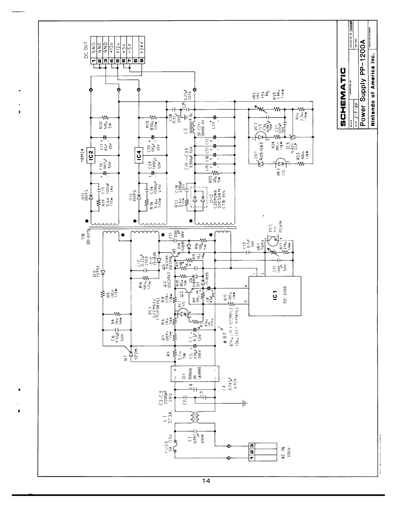
Power Supply Schematics ....... 2... 0.000666. 14
Monitor Schematics...
Parts Lists 00.00.00 ene tent e tere nett neers Body Parts Control Panel Assembly . . Wiring Harnesses . MDS P.C. Board Assembly .. Power Supply mMOODDd
Check before plugging the game in.
- LOCATION SETUP
VS. System — Upright is shipped ready for operation. Please check the following to insure proper operation:
- Check the exterior of the game for shipping damage, dents, chips, or broken parts.
- Remove the screws on the rear door panel.
- Unlock and open the rear door panel, as well as the service door, and inspect the interior of the game as follows:
- Check that all the plug-in connectors are firmly connected.
- Check all main subassemblies (monitor, power supply, control panel, etc.) to ensure they are securely mounted.
A. Game installation
- Requirements
Amperage: 1.8 AMPS Temperature: 0 to 38 degrees Celsius (32 to 100 degrees Fahrenheit) Humidity: Not over 95% relative Space required: 421%." x 33%." Height: 684"
B. Voltage selection
Before plugging in your game, make sure the terminal block of the power transformer is correct for your location's line voltage. See figure 1.
Outlet through O
Europe 200~240V
Power Supply Fuse tO
3A 125V +—— Isolation
Power Supply Assembly Transformer (for Left Monitor Only) q Leray
AC 100V Terminal Block (esieon
1oova US. 90~120V Fol , | iy Sou O
Main Fuse US.: 5A 125V ( 90~120V) Europe : 3A 250V (200 ~ 240V)
Power Transfomer PT-1021A Outlet through Isolation Transformer AC 100V 120VA MAX. b
(fer Right Monitor and’
Fluorescent Lamp
Power On/Off Switch
This game uses one of two types of transformers which are different in appearance but identical in function. The two types can be interchanged.
Fig. 1 Power Supply Assembly, Power Transformer and Voltage Selection
Cc. Power on/off switch
A power on/off switch is located in the rear of the game at the bottom left of the cabinet.
Please be sure you use a grounded outlet for this game. Failure to do so may result in destruction of electronic components.
D. Grounding of Game (Use only if 3 wire outlet is unavailable.) See Fig. 2
- A grounding wire should be connected to a grounding bar or a metal pipe which is firmly inserted into the ground.
- Do not connect the grounding to a water pipe, because polyvinylchloride pipes are sometimes used in water lines, and the electronic continuity to the ground may be interrupted.
- Absolutely do not connect the grounding wire to a gas pipe, as this can be extremely dangerous.
|. ADJUSTMENT
A. Adjustment of Video Monitor
INVERT OUT “| NON INVERT OUT In case of MDS-UP. plug in here!
~ yv-HOLO
H-CENT
BRIGHT
——— SOUND VOLUME
Fie OFA Matget Type
Fig. 3 Video Monitor
Do not touch the inside of the Video Monitor. it contains many parts supplied with high voltage.
MDS P.C. Board
oe Lis—LI LI
Swi Swe aaa VR3 V4 VR6 aga VI VR2VR5 MDS-CPU
Component Side pL
Cautions: (1) Since the Dip Switch settings (SW1, SW2) may be changed by new game software, refer to the new game instructions attached.
- Do not touch the fixed variable resistors (VR1, VR2, VR3, VR4, VRS, and VR6), as they have already been preset and do not need adjustment.
Il. MAINTENANCE AND REPAIR
A. Fuse Replacements
This game contains 4 fuses. Replace fuses only with the same type as listed below.
Specification of Fuses
- Main Fuse U.S. - 5A 125V ( 90~120V) Europe : 3A 250V (200~ 240V)
- Power Supply Fuse 3A 125V MIDGET
- Video Monitor Fuse 4A 125V 0.3A 125V MIDGET
B. Cleaning
The exterior of the game, all metal parts and all glass parts can be cleaned with a nonabrasive cleanser.
C. Operation Panel
- Operation Panel Removal Before repairing or replacing any switches or 8 way Controllers on the Operation Panel, unplug the game. Open the Service Door, and reach through the opening, and unlock the Clamps, located at each end on the underside of the Operation Panel.
- Micro-switch Replacement Whenever you replace any micro-switch on the Operation Panel, a switch gap adjustment is needed as shown in Fig. 4. This adjustment is not necessary for the player option buttons.
Press
Switch Button Assy.
Micro-switch Gap:0.2~0.5mmi 1/128 ~5'256inch)
SSS
Fig. 4 Switch gap adjustment
- Lubrication for 8 way Controller To maintain the 8 way Controller in good condition, lubricate the ball socket and 8 way Guide Plate approx. every 3 months. See Fig. 5.
Lubricate here//
Fig. 5 Lubrication points
D. Front Screen and Video Monitor Removal
- Front Screen Removal To remove the Front Screens, first remove the Control Panels by reaching through the Service Doors and releasing the Control Panel Clasps. Pull the bottom of the Front Screen toward you allowing it to drop into the slots. Then pull out toward center of game. See Fig. 6
Fig. 6 GP
- Video Monitor Removal If you need to remove the Video Monitor, follow the instructions listed below. But the following procedure should only be performed by an experienced service technician.
It is recommended the game be left unplugged for at least one hour before removing the Video Monitor. This will probably discharge the CRT, but extreme caution is still necessary.
- Make sure game is unplugged.
- Remove back door and unplug all the harnesses and cables from the Video Monitor.
- Standing at the front opening of the game, remove the four mounting machine screws and flat washers. See Fig. 7.
- Carefully lift the Video Monitor and pull out toward you.
Use extreme caution and do not touch electrical parts of the yoke area with your hands or with any metal object in your hands.
Remove the four mounting bolts and flat washers
—. Game PCB Removal
- Make sure the game is unplugged!
- Open the rear door panel
- Remove the 36 pin and 44 pin edge connectors from the right side of the FCC-PCBs on the shield cover.
- Pull out the 6 fasteners located on the perimeter of the shield cover. See Fig. 8
- Remove the 44 pin and 36 pin FCC short harnesses from the game P.C. board.
- Remove the game PCB from the shield cage by carefully sliding it straight out of the wooden PCB guides.
Fig. 8
Fastener
062-36P FCC PCB
SHIELD CAGE
062-44P FCC PCB
A reversed connector will damage your PCB! If the connectors don't slip on easily, don't force them!
IV. RADIO FREQUENCY INTERFERENCE
In order to protect against the RFI radiated from this equipment, please comply with the following. (A) Do not use non-Nintendo parts! (B) Do not modify your game circuitry! (C) Do not modify the wiring harness and connections! (D) Connect this game only to a grounded 3-wire outlet. (E) After servicing the Game PCB. shut the Shield Cover completely with the Fasteners. See Fig. 8. 40
MDS PCB
H H s H ie a ry 0 ole 062 44P FCC HARNESS 8 als o/s i‘ a ‘Guo. BUA fa a = als a ‘GND. BLACK a B ‘Gx. tax +84 olE ae ma ol \ei<
- ‘REO. a ED. fe! 2 o|® ca ae is 180 av SEAN @) \/t/2 a — te El als Z| —scomt BROWN o 3 aj Micon Rs fe cD 3 Scone BED 0 ey : McOm? RED o € SED. se et § BRED ‘BROWN Le ray 3 oREEN. Bown o AS ° i GheEN EEO ~ 8 | GND, ween 0 al 3 WGN. x L v : Sew nance 5 a BLUE A sre atu o #8 = wSYNC t ; & Tt 3 a _ onance wu a 26 ORANGE t A EOUNTER snows o : S COUNTER 0 M SERVICE youow S SERVICE SOUND. $ SOUNO | eno eam | eno sae GND BLACK
062 36P FCC HARNESS sack 4 a re < 3 eee rel x fea acnr sROWn, es tel MCRIGHT my 18181 $1 LerT ne——T2tZ | eH iarLer = ‘3; te] 4 Si UP RANGE tal . op wu YELLOW 1g 6 5 HE} —arsow Yettow a ra 3 YELLOW GREEN [eS aswrren | —Fettow oneen HE 3 F MUA SWITCH unr ewe a (3) & S18 Swen UGHT BLUE: hed 5 fe] ars emen TB QO fe & fe] —sseuecr Es t ry J wesrtrcrs < FI ° [a —sseuecrs PURPLE 2 MSELECT? ar a gy ° Sselecr? Gay 4 rd 2 wie 5 ; = | 3 i sow fa ° et "RED. u c) rae o Pi 1a ‘ORANGE, oO a vEtlow ‘4 6 FSi YELLOW. ° ‘ORAY Me ASWITGH “Gear Cr Sze switcH WHITE u BLACK BLACK. Re
UP 062 aa (> EDGE HARNESS ‘GND. | BROWN RED ‘ORANGE, wire Power conn
'S COUNTER
‘M COUNTER coloniole[inulouNrappYOIest2MalsaM aa abe mt v GREEN, asm cows oot
BLACK
WHITE
auacx 7 OfeSM!
40P Connector 44P Edge Connector
== ey
CHE!
062 44P FCC PC Board Nintendo of America ine |"
40P Connector
= 36P Edge Connector
ct
wilh I
SCHEMATIC
062 36P FCC PC Boat Nintendo of Ame‘ice ine. |
BIRD o-vueneves
rrvarss O88:
to wo
ud Cry
2 = POQQUTSPAGAVSH YOON F EEA Se o. BN al ous Qe Som f Orme Py oa 1g ; . on ste?
es 2764 2764 ‘ gedit e 4 ry va wy me
- 3 : i ; ; . OES ae FE theo = Et =" ;
—_—— oe : ; ; ee =
{i comm fim service ae pe an
mt tree
Be 5.2
oe Rss322230-4 at Ms jn a zt OOO srt crear =e: |) gr Soo
=; a : : : rad
=a! i : : : By
OM324 He 4m {7)scowms esate 45} s seavice
59, 1,14] VII MDS P.C. BOARD SCHEMATICS i Nintendo Gold. : * ow 9 . 10 ug 12 13 470 15 16 ov
mV
This page is a drawing, shown as the original scan.
i 1 T 2 T 3 4 T 5 T 6 XM-2001N SCHEMATIC DIAGRAM ©1984 Nintendo of America inc.
8 T 9
XM-200IN
To! w-1x018768 4 PoweR REGULATOR MARIO
X. PARTS LISTS A. Body Parts — See Figure 9
ITEM PART No. DESCRIPTION
1 MDSA-01-01 Body 2 MDSA-01-71 Top Center Trim 3 MDSU-01-56R Top Trim (Right) 4 MDSU-01-56L. Top Trim (Left) 5 TKGU-01-29 Fluorescent Lamp Ass'y 6 TKGU-01-29-01 Fluorescent Lamp TKGU-01-29-02 Lamp Starter (Glow Lamp) 7 *TENU-01-24-R (Tennis only) Name Plate with Overlay (Right) “TENU-01-24-01R (Tennis only) Name Plate Overlay (Right) MDSA-01-24-02 Name Plate Glass *TENU-01-24-L (Tennis only) Name Plate with Overlay (Left) *TENU-01-24-01L (Tennis only) Name Plate Overlay (Left) 8 MDSU-01-49-R Speaket Grill (Right) MDSU-01-49-L Speaker Grill (Left) TPPU-01-52 Monitor Support Bar MDSA-01-50 Center Monitor Mounting Bracket (Left) 9 MDSA-01-51 Center Monitor Mounting Bracket (Right) MDSA-01-53, Outer Monitor Bracket (Left) 10 MDSA-01-54 Outer Monitor Bracket (Right) 11 TKGU-20-00R Video Monitor (20-5F) (Right) (Inverted Scan) TKGU-20-00L Video Monitor (20-5F) (Left) (Standard Scan) TKGU-20-01 Video Picture Tube 12 MDSU-01-67 062 Monitor Front Cardboard 13 MDSU-01-68 062 Monitor Side Cardboard MDSA-01-23 Front Screen 14 MDSA-23-60R Complete Operation Panel Ass'y (Right) MDSA-23-60L Complete Operation Panel Ass'y (Left) 15 MDSA-01-73 Control Panel Center Piece 16 *TENU-11-14 (Tennis only) Instruction Label 17 TKGU-01-31 Draw Latch 18 TMAU-14-17 Service Door ADD-S2 Only 19 TMAU-14-18 Coin Selector AD-81P 20 TMAU-34-16 Lamp Socket BA-9S 21 TMAU-34-17 Lamp BA-9S 6.3V 0.15A TMAU-11-21 Cam Tamper Protection Plate TMAU-34-19 Micro Switch ADD D2MC-5F1 22 TMAU-14-12 Service Door Lock 23 TMAU-11-14 Cam B 31R 24 TMAU-14-11 Cash Door ADD 25 TMAU-14-12 Cash Door Lock 26 TMAU-11-27 Cash Box ADD 27 MDSU-01-32 CS Frame 120 W Ass'y
“Note: These parts will change from game type to game type.
A. Body Parts, continued — See Figure 9
ITEM PART No. DESCRIPTION
28 TKGU-01-11 Game Counter 29° TKGU-01-33 Service Switch TMAU-11-20 CS Plate 120W (Only) MDSA-01-72 T-Molding (Black) 30 MDSA-01-52 Monitor Bracket
A. Body Parts, continued — See Figure 10
ITEM PART No. DESCRIPTION
1 TKGU-01-61 Vent Grill 2 MDSA-01-01-05 Back Door 3 TKGU-01-03 Back Door Lock (Key#6510) TKGU-01-03-01 Back Door Key Only (Key#6510) 4 TKGU-01-05 Cam A-Type (Back Door Lock) 5 MDST-21-11 P.C. Board Ass'y (Specify Game Type) 6 MDSU-01-01-11 062 FCC Shield Cover 7 MDSU-01-01-12 062 44P FCC P.C.B. Ass'y 8 MDSU-01-01-13 062 36P FCC P.C.B. Ass'y 9 MDSU-23-35 Snap In Fastener TPPU-01-01-14 CHPU-01-01-15 TKGU-01-08 TKGU-01-10 TKGU-01-65 TKGU-11-08 TKGU-01-30 CHPU-01-01-10 MDSU-08-00 CHPU-08-01 CHPU-18-01 CHPU-11-12 CHPU-11-13 TKGU-01-43 TKGU-01-07 MDSA-11-05 TPPU-11-25 TKGU-11-17 MDSU-20-09 MDSU-23-61 TENU-11-01 FCC Sponge (Black) Shield Cover Label Power Cord 5M Strain Relief Bushing Strain Relief Bushing Plate Fuse 5A 125V Caster Shield Cage (054 Type) Power Supply (PP-1200A) Power Transformer (PT-1021A) Power Transformer (PT-1021B) Power Transformer Bracket 100 Power Transformer Bracket 120 Speaker (16 cm) Back Door Lock Stopper Plate MDS-UP Back Door Label FCC Label Monitor Adjustment Label Monitor Frame MDS Manual & Schematics VS. Tennis Manual
This page carries no recoverable text. It is a drawing or a photograph. See the original scan.
Fig. 10
B. Control Panel Assembly — See Figure 11
{TEM PART No. DESCRIPTION
MDST-14-12 TKGU-23-21 TNX-23-18 TKGU-23-17 TKGU-23-16 TKGU-23-20 TKGU-23-22 TKGU-23-23 TKGU-23-13 TMAU-12-15 TMAU-12-14 TMAU-12-16 TMAU-11-18 MDSA-01-22R MDSA-01-22L TKGU-23-12 TMAU-34-18 MDSU-12-17 TKGU-23-26 TKGU-23-34 MDST-12-21 MDST-12-17 MDSA-23-29 MDSA-23-30 MDSA-23-31 TMAU-11-19 TMAU-12-18 8 Way Control Level Assembly Switch Collar 8 Way Guide Plate Switch Spacer Bearing Braker Spring Stopper Lever Spring E-Ring Micro Switch Lever Plate Control Knob Plate Control Knob Collar 8L Knob with Shaft 80.5L Control Panel Base (Right) Control Panel Base (Left) Switch Button Bracket Micro Switch VL12L (Straight) Black Sponge, 2 x 10 x 580L Nut Plate Pal Nut M16 Button Assembly (Black) Button Assembly (Crimson) Switch Collar Switch Bezel Switch P163 C3RU Operation Panel Fastener B 38 W Collar — 34 x 28x 7H
This page carries no recoverable text. It is a drawing or a photograph. See the original scan.
C. Wiring Harnesses
PART No. DESCRIPTION MDSU-41-12 062 44P FCC Harness MDSU-41-11 062 36P FCC Harness MDST-41-13 UP 062 44P Edge Harness MDST-41-14 UP 062 36P Edge Harness MDST-41-11 UP 062 15P SW. Harness MDST-41-12 UP 062 12P SW. Harness TPPU-93-02 2P-400 Audio Harness (400 mm) TPPU-93-07 6P-600 Video Harness (600 mm) TMAU-41-14 4P-600 WL Coin Harness (600 mm) TMAU-41-13, 4P-800 Service Switch Harness (800 mm) TMAU-41-12 3P-500 Game Counter Harness (500 mm) TKGU-13-17 2P-860 Speaker Harness (860 mm) MDSU-42-01 062 Grounding Ribbon 720L MDSU-42-02 062 Grounding Ribbon 620L MDSU-42-03 062 Grounding Ribbon 1320L MDSU-42-04 062 Grounding Ribbon 1420L. MDSU-42-05 062 Grounding Ribbon 180L. MDSU-42-06 062 Grounding Ribbon 1600L MDSU-42-07 062 Grounding Ribbon 530L MDSU-42-08 062 Grounding Ribbon 840L MDSU-42-09 062 Grounding Ribbon 1700L
D. MDS P.C. Board Assembly
PART No.
MDST-21-11 MDST-21-12 MDST-21-13 MDST-21-14 MDST-21-15 MDST-21-16 MDST-21-17 MDST-21-18 MDST-21-19 MDST-21-20 MDST-21-21 MDST-21-22 MDST-21-23 MDST-21-24 MDST-21-25 MDST-21-26
MDST-21-27 MDST-21-28 MDST-21-29 MDST-21-30 MDST-21-31 MDST-21-32 MDST-21-33 MDST-21-34
MDST-21-35
MDST-21-36 MDST-21-37 MDST-21-38 MDST-21-39 MDST-21-40
MDST-21-41 MDST-21-42
MDST-21-43 MDST-21-44 MDST-21-45 MDST-21-46
MDST-21-47 MDST-21-48 DESCRIPTION (Reference Designations and Locations)
P.C. Board Assembly 2A03 Microprocessor (2J,8J) HM6116 2kX 8bit Static RAM, 250ns (1E, 6E) MB8416-15 2kX 8bit Static CMOS RAM 150ns (8L) TC5533P-A 4k xX 8bit Static RAM (2C) TC5533P-B 4kxX 8bit Static RAM (8C) 74LSO00 Quad 2-input NAND LS TTL (4C, 5C) 74LS04 Hex Inverters LS TTL (1L, 2K, 4E, 5E) 74LS10 Tri 3-input NAND LS TTL (4D) 74LS32 Hex 2-input AND LS TTL (4A, 4B, 5A, 5B) 74LS74 Dual D-Flip Flops LS TTL (5D) 74LS123 Dual Retriggable Single Shots LS TTL (1d) 74LS138 Dual 2 to 4 Demultiplexers LS TTL (1F, 6F) 74LS157 2 to 1 Data Selectors LS TTL (5J, SK, 6J, 6K) 74LS165 8bit Shift register LS TTL (6M, 6N, 7P, 8P) 74LS240 Octal 3 State Bus Inverters LS TTL (7M, 7N, 8M, 8N) 74LS245 Octal 3 State Bus Tranceivers LS TTL (3K, 8K) 74LS373 Octal 3 State D-Latchs LS TTL (2E, 8E) 74F04 Hex Inverters FAST TTL (5H) 4066 Quad Analog Switches C-MOS (2P, 4P) LM324 Hex Operational Amplifiers (1P, 3P) LM3900 Hex Operational Amplifiers (5N, 5R) PST518A Reset IC (1K) 2SA933 Silicon PNP Transistor (Q3, Q7, Q13~Q16, Q19~Q22, Q26, Q27) 28C1740 Silicon NPN Transistor (Q1, Q2, Q4~Q6, QB, QY, Q12, Q17, Q18,Q23~Q25) 2SD592 Silicon NPN Transistor (Q10, Q11) 1S953 Silicon Switching Diode (D1, D2,D5,D7, D9~D11) WO03B Silicon Diode (D3, D4, D6, D8) 270 1/4W +5% Resistor (R4) 330 1/4W +5% Resistor (R22, R30, R36, R38, R45~R47, R72, R89) 1009 1/4W +5% Resistor (R79, R80, R95, R97) 3300 1/4W +5% Resistor (R8, R20, R28, R29, R48, R49, R70, R71, R73, R91) 6800 1/4W +5% Resistor (R119) 1KQ 1/4W +5% Resistor (R31, R382, R92, R93) 1.2KQ 1/4W +5% Resistor (R37, R43) 2.2KQ. 1/4W +5% Resistor (R6, R11, R12, R14, R15, R23, R24, R27, R39~R42, R50, R51, R54, R55, R64, R65, R68, R69, R81, R87) 3.3KQ 1/4W +5% Resistor (R77) 4.7KQ 1/4W +5% Resistor (R13, R17, R25, R26, R52, R53, R66, R67)
D. MDS P.C. Board Assembly (continued)
PART No. DESCRIPTION (Reference Designations and Locations) MDST-21-49 10KQ 1/4W +5% Resistor (R3, R5, R7, R16, R18, R19, R21, R33, R56~R63, R75, R82, R83, R85, R86, R120) MDST-21-50 12KQ 1/4W +5% Resistor (R76, R96, R98) MDST-21-51 20KQ 1/4W +5% Resistor (R94, R99) MDST-21-52 33K 1/4W +5% Resistor (R1, R2) MDST-21-53 100KQ 1/4W +5% Resistor (R10, R35, R84, R103, R121) MDST-21-54 150KQ 1/4W +5% Resistor (R74, R118) MDST-21-55 360KQ 1/4W +5% Resistor (R107, R114) MDST-21-56 750KQ 1/4W +5% Resistor (R101, R108, R109, R110, R115, R116) MDST-21-57 1IMQ 1/4W +5% Resistor (R102, R106, R112, R117) MDST-21-58 1.8MQ 1/4W +5% Resistor (R90, R105) MDST-21-59 2.2MQ 1/4W +5% Resistor (R81, R87, R100, R104) MDST-21-60 1KQX8 Series Resistor Array (RM1, RM2, RMS, RM8, RM11, RM14, RM17) MDST-21-61 680X4 Parallel Resistor Array (RM3, RM4, RM6, RM7, RMQY, RM10,RM12, RM13, RM15, RM16) MDST-21-62 33pF 50V Ceramic Disc Capacitor (C35, C91, C92) MDST-21-63 68pF S5O0V Ceramic Disc Capacitor (C25, C86) MDST-21-64 100pF SOV Ceramic Disc Capacitor (C38, C42, C43, C46) MDST-21-65 220pF SOV Ceramic Disc Capacitor (C26~29, C34, C45) MDST-21-66 0.014F 50V Ceramic Disc Capacitor (C9, C10, C89, C90) MDST-21-67 O0.1u4F 25V Ceramic Disc Capacitor (C100~C178) MDST-21-68 0.2uF 12V Ceramic Disc Capacitor (C4, C12) MDST-21-69 0.0474F 50V Film Capacitor (C37, C39, C40, C44) MDST-21-70 3.3uF 16V Al. Electrolytic Capacitor (C15~C18, C31, C32) MDST-21-71 10uF 16V Al. Electrolytic Capacitor (C3, C5, C6, C11, C13, C14, C19~C24, C30, C33, C36, C41, C47~C85) MDST-21-72 A7uF 16V Al. Electrolytic Capacitor (C2) MDST-21-73 100uF 16V Al. Electrolytic Capacitor (C1) MDST-21-74 100uF 25V Al. Electrolytic Capacitor (C8) MDST-21-75 470uF 16V Al. Electrolytic Capacitor (C7, C87, C88) MDST-21-76 5009 Variable Resistor, Red Cap (VR1, VR3) MDST-21-77 500 Variable Resistor. Green Cap (VR2, VR4) MDST-21-78 500 Variable Resistor, Blue Cap (VR5, VR6) MDST-21-79 21.47727MHz Crystal (X1) MDST-21-80 8 position dip switch (SW1, SW2) MDST-21-81 28P IC socket (1A, 1B, 1C, 1D, 2A, 6A, 6B, 6C, 6D, 8A, 8B) MDST-21-82 40P IC socket (2F, 2J, 8F, 8J) MDST-21-83 Type 32-4 (UM3~X 2) Battery Case MDST-21-84 Bolt with washer M2.6 MDST-21-85 Flat washer M2.6 MDST-21-86 Nut Plate M2.6 MDST-21-87 Dry Battery “AA” T18L Beaded tie
E. Power Supply
PART No. DESCRIPTION MDSU-08-00 Power Supply Unit (PP-1200A) MDSU-08-01 Transistor 2SC2562 or 2SC3239 (Q2) MDSU-08-02 Transistor 2SC2749 or 2SC2938 (Q3) MDSU-08-03 Photo Coupler* (S22MD1V) or (TLP541G) (PC1) MDSU-08-04 Photo Coupler (PC614) (PC2) MDSU-08-05 Hybrid IC (3D-3000) (IC1) MDSU-08-06 IC (MPC78M24) (IC2) MDSU-08-07 IC (TL431CLP) (IC3) MDSU-08-08 IC (MPC78M1 2) (IC4) MDSU-08-09 Transformer (3D-01 73) (TR) MDSU-08-10 Choke Coil SC2A (L1) MDSU-08-11 Choke Coil SF-C27-00105-01 (L2) MDSU-08-12 Fuse Holder 0G751-0062 MDSU-08-13 Fuse 3A 125V MDSU-08-14 Resistor 5.1 OHM 5W (Cement) (R1) MDSU-08-15. Resistor 30 OHM 5W (Cement) (R10) MDSU-08-16 Resistor 100 OHM 5W (Cement) (R16) MDSU-08-17 Resistor 510 OHM 5W (Cement) (R20) MDSU-08-18 Resistor 20 OHM 5W (Cement) (R22) MDSU-08-19 Resistor (carbon) 100 KOHM ‘2W (R3, 14) MDSU-08-20 Resistor (carbon) 100 OHM */2W (RS) MDSU-08-21 Resistor (carbon) 5.6 OHM %2W (R18, 19, 21) MDSU-08-22 Resistor (carbon) 820 OHM ¥2W (R13) MDSU-08-23 Resistor (carbon) 1 KOHM “sW (R4, 6, 15) MDSU-08-24 Resistor* (carbon) 47 KOHM or 10 KOHM W (R7) MDSU-08-25 Resistor (carbon) 27 KOHM ‘aW (R8, 17) MDSU-08-26 Resistor (carbon) 100 OHM VaW (RQ, 11, 12, 23, 24) MDSU-08-27 Resistor (carbon) 1.8 KOHM ‘%4W (R25) MDSU-08-28 Resistor (carbon) 2.7 KOHM %4W (R26) MDSU-08-29 Variable Resistor 50 KOHM (VR1) MDSU-08-30 Variable Resistor 2 KOHM (VR2) MDSU-08-31 Film Capacitor 0.047MF 630V (C1.4) MDSU-08-32 Film Capacitor 0.22MF 250V (C10, 28, 29) MDSU-08-33 Ceramic Capacitor 2200PF 2KV (C2, 3,11, 14,15, 18) MDSU-08-34 Electro Capacitor 330MF 200V (C5) MDSU-08-35, Electro Capacitor 100MF 50V (C16, 24) MDSU-08-36 Electro Capacitor 4.7MF 50V (C7) MDSU-08-37 Electro Capacitor 47MF 35V (C8, 17) MDSU-08-38 Electro Capacitor 100MF 25V (C25) MDSU-08-39 Electro Capacitor 3300MF 10V (C19, 20, 21, 22, 23) MDSU-08-40 Mylar Capacitor 1000PF SOV (C12) MDSU-08-41 Mylar Capacitor 0.01MF 50V (C6, 9, 27) MDSU-08-42 Mylar Capacitor 0.1MF 50V (C13)
*Note: The 522MDIV uses R7 of 47 KOHM and the TLP541G uses R7 of 10 KOHM
E. Power Supply (continued)
PART No. DESCRIPTION
MDSU-08-43 Mylar Capacitor 0.047MF S50V (C26) MDSU-08-44 Bridge Rectifier S4V840 (D1) MDSU-08-45 Diode 1S954 (D3) MDSU-08-46 Diode 151835 (D6. 7, 10, 14) MDSU-08-47 Diode 30DF2 (D11, 15) MDSU-08-48 Diode CTB-33S (D12) MDSU-08-49 Zener Diode RD 5.1EB3 (ZD1, 5.1 Volt) MDSU-08-50 Thyristor 5P2M (Q1) MDSU-08-51 Connector 1 (CON1) MDSU-08-52 Connector 2 (CON2)
© 1984 Nintendo of America Inc. PRINTED IN U.S.A.