Centipede DP-182-1st-01A
Centipede (revision 4) (Atari, 1980) · Drawing Package · 1 pages · original scan
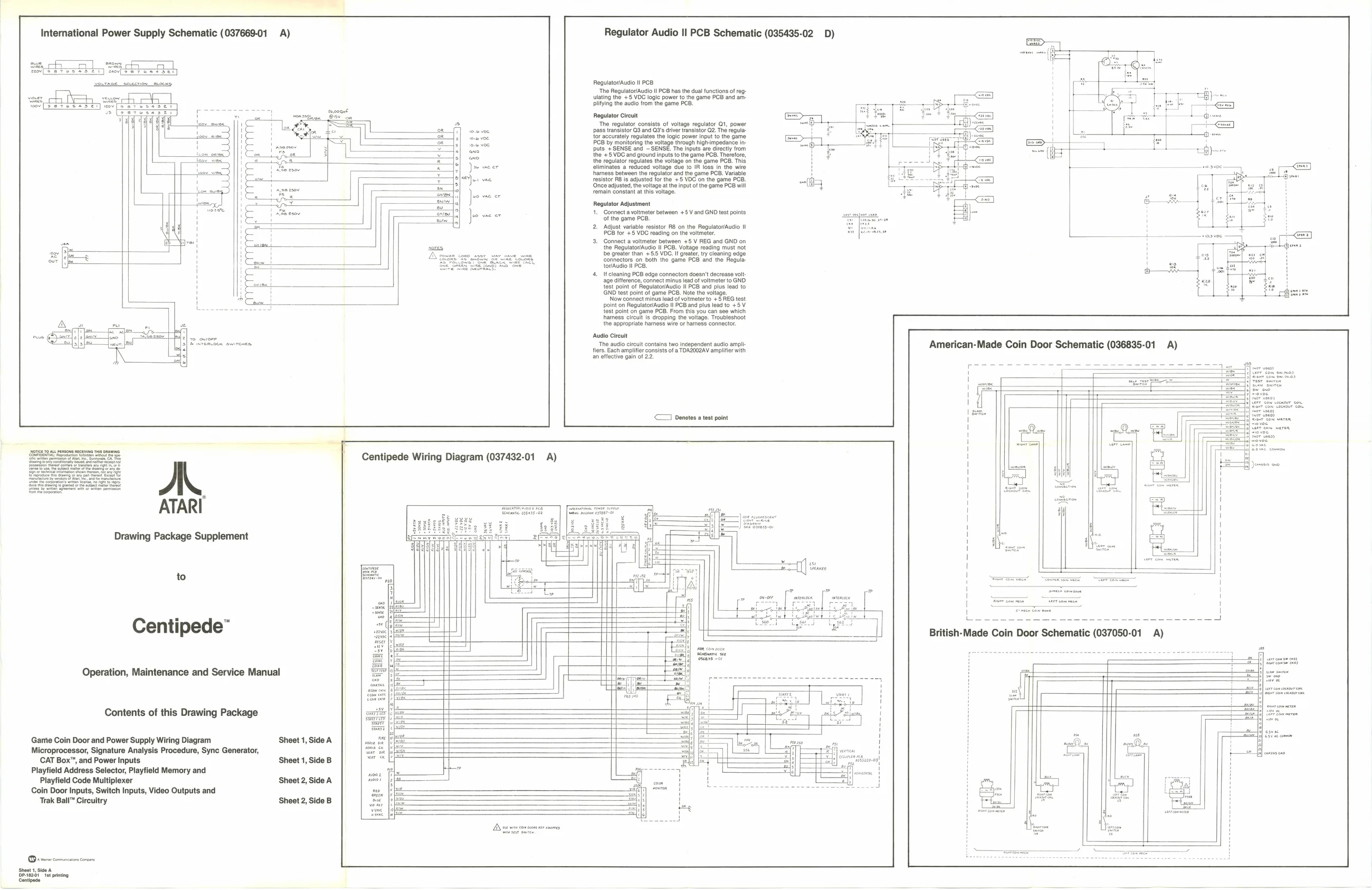
International Power Supply Schematic (037669-01 A) Regulator Audio II PCB Schematic (035435-02 D)
Regulator/Audio Il PCB ‘The Regulator/Audio Il PCB has the dual functions of reg- Ulating the +5 VOC logic power to the game PCB and amplifying the audio from the game Regulator Circuit ‘The regulator consists of voltage regulator Q1, power ass transistor Q3 and Q3's driver transistor Q2. The regula- {or accurately regulates the logic power input to the game CB by monitoring the voltage though highmpedance in-
puts +SENSE and — SENSE. The Inputs are directly trom harness between the regulator and the game PCB. Variable
{ho + 5 VOCand ground input the game PCB. Theetre, {the regulator regulates the voltage on the game PCB, This climinates a reduced voltage due to IR loss in the wire
resistor RB is adjusted for the +5 VOC on the game PCB.
‘Once adjusted, the voltage atthe input of the game PCB will
remain constant at this voltage. Regulator Adjustment
1. Connect a voltmeter between +5 V and GND test points
‘of the game PCB. ‘Adjust variable resistor RB on the Regulator/Audio Il PCB for +5 VDC reading on the voltmeter.
- Connect a voltmeter between +5 V REG and GND on the Regulator/Audio Il PCB. Voltage reading must not be greater han + 8. VDC. It great, tr cleaning edge rectors on both the game PCB and the Regula fovaudio PCB If cleaning PCB edge connectors doesn't decrease volt
age difference, connect minus lead of voltmeter to GND ‘Now connect minus lead of volmeter to +5 REG test
test point of Regulator/Audio II PCB and plus lead to GND test point of game PCB. Note the voltage.
point on Regulator/Audio ll PCB and plus lead to +5V {est point on game PCB. From this you can see which hhamess circuit is dropping the voltage. Troubleshoot i the appropriate harness wire or harness connector.
a yo owoer ‘Audio Circuit Pentencen arenes ‘The audo cet contain two independent audio ampli
<1 Denotes a test point
Centipede Wiring Diagram (037432-01 A)
ATARI
Drawing Package Supplement Seunte aibess-08 wo mane S8887 3
to
& EL ees
British-Made Coin Door Schematic (037050-01 A)
Centipede”
Operation, Maintenance and Service Manual a
Contents of this Drawing Package i ' Game Coin Door and Power Supply Wiring Diagram Sheet 1, Side A H t Microprocessor, Signature Analysis Procedure, Sync Generator, i CAT Box", and Power Inputs Sheet 1, Side B iano) Playfield Address Selector, Playfield Memory and * ims | Playfield Code Multiplexer Sheet 2, Side A oe j Coin Door Inputs, Switch Inputs, Video Outputs and res ; Trak Ball” Circuitry Sheet 2, Side B ae
Berens
Dem cmmncein cn Sheet 1, Side A Devez6t et printing Centipede