Asteroids DP-143-1st-01B
Asteroids (rev 4) (Atari, 1979) · Drawing Package · 1 pages · original scan
CLOCK CIRCUIT
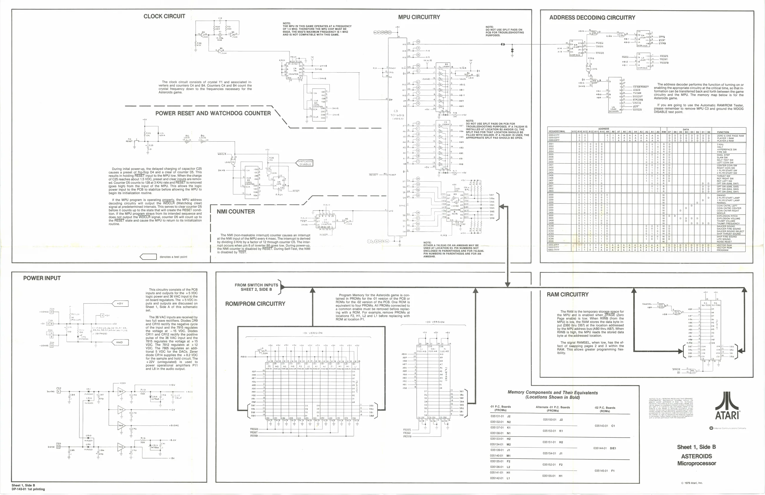
‘The clock circuit consists of crystal Y1_and associated inverters and counters 4 and 84. Counters C4 and 84 count the ‘orystal frequency down to the frequencies necessary for the ‘Asteroids game,
SS POWER RESET AND WATCHDOG COUNTER \ Nove: THE MPU IN THIS GAME OPERATES AT A FREQUENCY OF 1's MHZ. THEREFORE THE MPU CHIP MUST BE ‘sdk, THE 6502'S MAXIMUM FREQUENCY 181 MHZ SANO 1s NOT COMPATIBLE WITH THIS GAME.
MPU CIRCUITRY
Nove 100 NOT USE sPLiT pADS OW Pee FoR TROUBLESHOOTING PuRPoses.
ADDRESS DECODING CIRCUITRY
Te
During inital power-up, the delayed charging of capacitor 25, ‘causes a preset of flipfiop D4 and a clear of counter 05. This results in holding FESET ‘of 025 reaches about 1.5 VOC, preset and clear inputs are remov-
‘ed, Counter D5 counts fo 128 at 3 KHz rate and RESET Is removed
{goes high) from the input of the MPU. This allows the logic Power input to the PCB to stabilize before allowing the MPU to begin its initialization routine.
Input to the MPU low. When the charge
IH the MPU program is operating properly, the MPU address decoding circuitry will output the (Watchdog clear) signal at predetermined intervals. This serves to clear counter D5 before it counts up to the state that will create the RESET condition. If the MPU program strays from its intended sequence and does not output the ‘signal, counter D5 will count up to the RESET state and cause the MPU to retum to it initialization
TT ants sine es a a ee ee Tm COUNTER
is disabled by TEST. ee |
a
DO NOT use SPLIT PADS on P ‘TROUBLESHOOTING PURPOSES. IFA 74124818 INSTALLED AT LOCATION 82 ANDIOR C2, THE + SPLIT PAD FOR THAT LOCATION SROUL ILLED WITH SOLDER. IFA P4LS244 IS USED, THE +95 APPROPRIATE SPLIT PAD SHOULD BE OPEN,
DISABLE test point. ‘The address decoder performs the function of turning on or enabling the appropriate circuitry atthe critical time, sot {formation can be transferred back and forth between the game Circuitry and the MPU. The memory map below Is for the
It you are going to use the Automatic RAM/ROM Tester, please remember to remove MPU C3 and ground the WOOG
POWER INPUT
This circuitry consists of the PCB Inputs and outputs for the +5 YDC logic power and 36 VAC input tothe ‘on board regulators. The +5 VDC inputs and outputs are discussed on ‘Sheet 1, Side A of this schematic set ‘The 36 VAC inputs are received by two full wave rect ‘and R10 rectify Of the input and the 7915 regulates the voltage at -15 VDC. Diodes: CRI and CRI2 rectty the positive pulse of the 36 VAC input and the 7815 regulates the voltage at +15, VOC. The 7812 regulates at +12 VDC. The 7805 regulates an addi. tional 5 VDC for the DACs. Zener diode CRI4 supplies the +8.2 YOC for the sample and hold circult. The +22V (unregulated) is used 0 ower operational amplifiers P1t and LB in the audio output
P-143-01 1st printing FROM SWITCH INPUTS SHEET 2, SIDE B
ROM/PROM CIRCUITRY
ia
tecea Program Memory for the Asteroids game is contained in PROMS for the -01 version of the PCB or OMS for the -02 version of the PCB. One ROM is. ‘equivalent to four PROMS. All PROMs connected to ‘a common enable must be removed before replac:ing with a ROM. For example, remove PROMS at locations F2, Hi, L2 and Li belore replacing with ROM at location Ft.
Prom Frou -o2 version
caniee’s) ‘bility.
Memory Components and Their Equivalents (Locations Shown in Bold)
01 P.C. Boards Alternate 01 P.C. Boards (PROMS) (PROMS) RAM CIRCUITRY
‘The RAM is the temporary storage the MPU and is enabled when Page enatie) is low. Whon FYWE (from the MPU) is fow, the RAM stores the data byte in put (DBO thru DB) atthe location addressed By the MPU adaress bus (ABO thru AB7), When RIWE Is hgh, the MPU reads the stored data byte atthe addressed location.
‘The sigral RAMSEL, when low, has the of: fect of swapping pages 2 and 3 within the RAM. This allows greater programming flex-
03513101 42
| 03519201 | N2 | enim |
casia70r Kt
| aren | ossiss01 | Kt |
oasisso1 He
| ossiseor | m2 | posisroy | Me |
sweet
| hae | ossis401 | at |
3513501 Fe
| sien | oasts201 | Fe |
caster Ht
| oasiaz01 | 1 | Sree | a |
Ss so ID
Sheet 1, Side B ASTEROIDS Microprocessor
© 1079 Ata, ne.