Asteroids DP-143-7th-02A
Asteroids (rev 4) (Atari, 1979) · Drawing Package · 1 pages · original scan
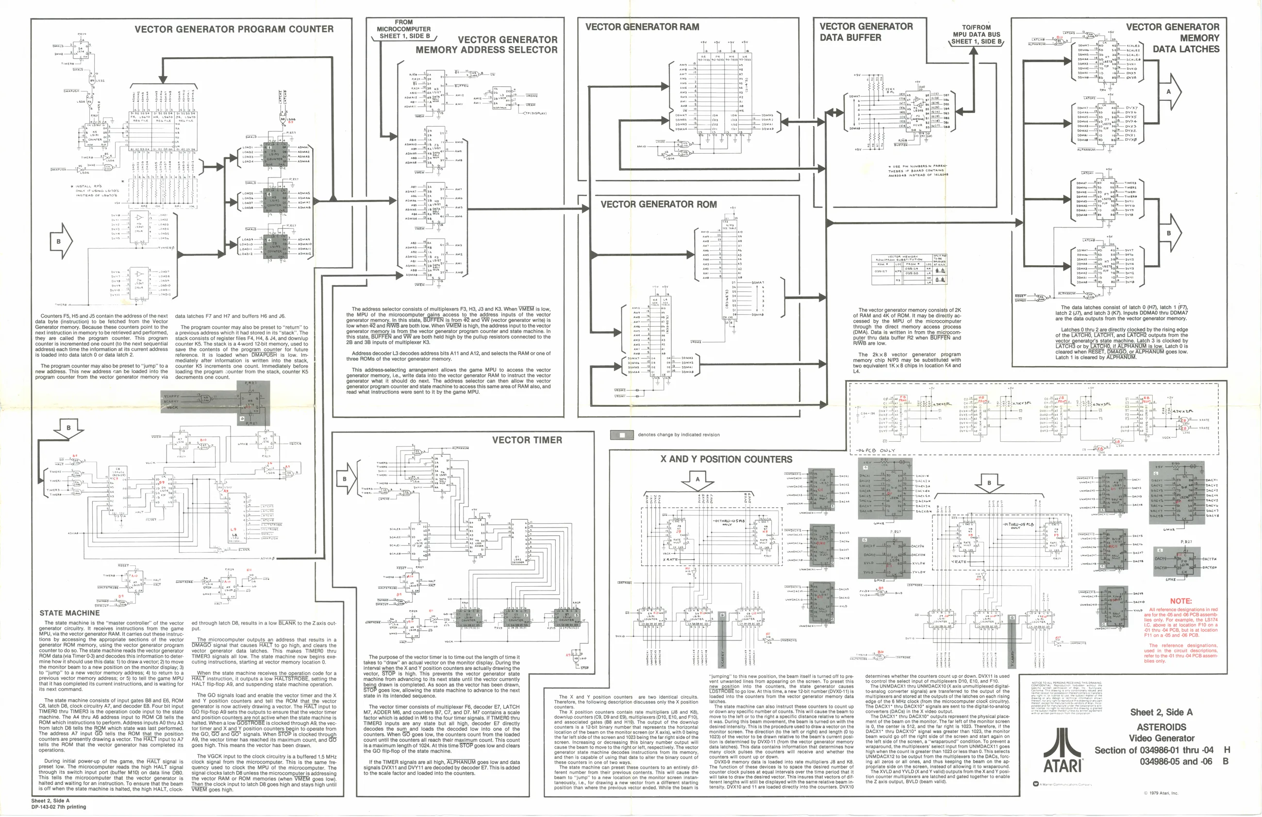
PROGRAM COUNTER wicROCOMPUTER VECTOR GENERATOR RAM
pHEET 1, SIDES VECTOR GENERATOR MEMORY ADDRESS SELECTOR VECTOR GENERATOR DATA BUFFER TOIFROM MPU DATA BUS SHEET 1, SIDE B VECTOR GENERATOR MEMORY a p—:] DATA LATCHES
‘The data latches consist of latch 0 (H7) latch 1 (7), latch 2 V7), and latch 3 (K7). Inputs DDMAG thru DOMA? are the data outputs trom the vector generator memory. Latches othr 2 are airectyelocked bythe rising edge
are the data outputs trom the vector generator memory of the LATCH, LATCHT, and LATCH? outputs from the
veel generat’ tate macine. Lateh 3 cocked by cared wien RESET, BMAGO, ov ALPHANUM goes low. a 4 on 008 low. Latch 1 is cleared by ALPHANUW, VECTOR GENERATOR
<riosn)
‘The address selector consists of multiplexers F3, H3, J3 and K3. When VIEW is ow,
the MPU of the microcomputer gains access 1a the adress inputs tthe vector
generator In this state, 's from 2 and YW (vector generator writ) is,
ow when &2 and FUWE are both iow. When VMEEM Is high, the address input to the vector {Generator memory Is from the vector generator program counter and state machine. In this stato, ‘and VW are both held high by the pullup resistors connected to the 2B and 38 inputs of multiplexer K3. ‘Address decoder L3 decodes address bits A11 and A12, and selects the RAM or one of three ROMS of the vector generator memory.
‘The vector generator memory consists of 2K
of RAM and 4K of ROM. It may be directly ac- ‘cessed by the MPU of the microcomputer through the direct memory access process (OMA). Data is written in from the microcom- DDuter thru data butter R2 when BUFFEN and MWB are low. ‘Counters F5, HS and JS contain the address of the next data latches F7 and H7 and butfers H6 and J6. data byte (instruction) to be fetched trom the Vector Generator memory. Because these counters point to the The program counter may also be preset t ‘ext instruction in memory tobe retrieved and performed, a previous address which it had stored in its they are called the program counter. This program stack consists of register fles F4, H4, & J, and dowrlup ‘counter is incremented one count (o the next sequential counter KS. The stack is a 4-word 12-bit memory, used to address) each time the information at its current address save the contents of the program counter for future | loaded into data latch 0 or data latch 2. reference. It is loaded when DMAPUSH is low. Immediately alter information 1s written into the stack, ‘The program counter may also be preset to “jump” toa counter KS increments one count. Immediately before new address. This new address can be loaded into the loading the program ounter from the stack, counter KS ‘Program counter from the vector generator memory via _ decrements one count. The 2kx8 vector generator program memory chip NIP3 may be substituted with
two equivalent 1K3x8 chips in location Ké and
This address-selecting arrangement allows the game MPU to access the vector ‘generator memory, i2., write data into the vector generator RAM to instruct the vector ‘Generator what It'should do next. The address selector can then allow the vector ‘Generator program counter and state machine to access this same area of RAM also, and ‘ead what instructions were sent to It by the game MPU.
VECTOR TIMER
2p!
covrmmscosna
—somag
i
oe NOTE: wie _Allrerence designations in rec are for the-05 and 08 PCB assomb- Ties ony. For example, the LS174 LG: above is at location F10 on a “01 thea 04 PCB, but fea location Fit'on 05 and 06 PCB, ‘STATE MACHINE ‘The state machine is the “master controller” of the vector ed through latch D8, results in @ low BLANK to the Zaxis out. generator circuitry. it receives instructions from the game put MPU, via the vector generator RAM. It carries out these instruc: tions by accessing the appropriate sections of the vector The microcomputer outputs an address that results in a (Generator ROM memory, using the vector generator program | DMAGO signal that causes HALT to go high, and clears the Counter to do so. The state machine reads the vector generator vector generator data latches. This makes TIMERO thru ROM data via Timer 0-3) and decodes this information to deter. TIMERS signals all low. The state machine now begins exe- ‘mine how it should use this data: 1) to draw avector,2)to move _cuting Instructions, starting at vector memory location O. the monitor beam to a new position on the monitor display; 3) to “jump” to a new vector memory address; 4) to return to @ _When the state machine recelves the operation cade for a Provious vector memory address; or6) to tell the game MPU HALT instruction, it outputs a low HALTSTROBE, scting the that ithas completed its current instructions, andis waiting for HALT flipflop A9, and suspending state machine operation. its next command. ‘The reference. designations, used Inthe ceult deseriptions, Feterto the 01 tru-04 PCB assem Biles only “The purpose ofthe vector timer isto time out the length of time it takes to “draw” an actual vector on the monitor display. During the Interval when the X and Y position counters are actually drawing the vector, STOP Is high. This prevents the vector generator state ‘machine trom advancing to its next state until the vector curently ‘being drawn is completed. As soon as the vector has been drawn, TOE goes low, alowing the state machine to advance fo the next State in its intended sequence. “jumping” to this new po tion, the beam ise is tuned off to pre: determines whether the counters count up or down, DVXA1 is used vont unwanted lines from appearing on the screen. To preset this to control the select input of multiplexers O10, 16, and F10 Few ‘position into. the “counters, the stato gonerator causes The UNMDACX thru UNMOACX10 O axis unmultiplexed dita EBSTROBE to colon. At this time, anew 1201 number(OVXO"i)is__toanalog converter signals) are transerrd tothe output of the ‘Tne X and Y position counters are two identical circuits, loaded into the counters tom the vector generator memory data multiplexers and stored at the outputs ofthe latches on each ising ‘Tnorefore, the following description dlecusses only the X position latches. (20g0 of the 6 MHz clock (rom the microcomputer clock circutry). counters “Tho state machine can also instruct these counters to count up The DACX'" thru DAGX10" signals ae sent tothe digtabtoanalog “The X position counters contain rate multipliers (J8 and Ks), ‘convertors (OACS) Inthe X video output downlup counters (69, D9 and E9), multiplexers (10, £10, and F10), "The OACK'" thru DAGX10" outputs represent t land associated gates (68 and Hi0). The output of the down! 25 binary number that represents the horizon right Ye 1028. Thretore, tthe ‘beam on the monitor sereen (or X axis with being Monitor sorean. Tho direction (to the left or right) and length (0 to nal was greater than 1023, the monitor ‘tho fa let sie ofthe eerean and 1023 being the far right 4023) ofthe vector to be drawn relative tothe Boam’s curent posi. Beam would go off the right. ‘soreen and stat again on tion Is determined by OVX0-11 (rom the vector generator memory the lft side ofthe screen, a “wraparound” condition, To prevent a ‘ata latches). This data contains Information that determines how "elect input from UNMOACXY goes many’ clock pulses the counters. will receive and whether tho ts The GO signals toad and enable the vector timer and the X ‘The state machine consists of input gates 88 and E6, ROM and Y position counters and tell the ROM thal the vector 8, latch D8, clock circuitry A7, and decoder E8. Four bit input generator is now actively drawing a vector. The HALT input to ‘TIMERO thru TIMERS is the operation code input to the state GO flipfop AQ sets the outputs to ensure thatthe vector time ‘machine. The A4 thru AB address input to ROM C8 tells the and position counters are not active when the state machine is ROM which instructions to perform. Address inputs AO thru A3_halted. When a low GOSTROBE ls clocked through Aa, the vec: {rom latch 8 tells the ROM which state was last performed. tor timer and X and Y position counters begin to operate from ‘The address A7 input GO tells the ROM that the position the GO, GO and GO* signals. When STOP is clocked through counters are presently drawing a vector. The HALT input to A7 9, the vector timer has reached its maximum count, and tells the ROM that the vector generator has completed its goes high. This means the vector has bean drawn, ‘operations. ‘The vector timer const of multiplexer F6, decoder £7, LATCH M7, ADDER M6, and counters BY, C7, and DY. M7 contains a scale {ackor whichis added n MB tothe four timer signals TIMERO they TIMERS Inputs aro any state but all high, decoder E7 directly decodes tho sum. and loads the. decoded low Into one of the ounters. When 8 9088 low, the counters count from the loaded ount unl the counters all reach ther maximum count. This count is. amaximum length of 1024. At this time STOP goes low and clears. the GO tpop ofthe state machine Sheet 2, Side A ASTEROIDS Video Generator
The VGCK input to the clock ciculty is a butfered 1.5 MHz ‘Counters wil eount up or down. UNMDAGK12 to be output from the multiplexers tothe DACs, ore During initial powerup of the game, the HALT signal is clock signal from the microcomputer. This is the same fre: It the TIMER signals are al high, ACPHARUM goes low and data {hese counters in one of two. ‘OVx09 memory datas loaded nto rate multipliers JB and K8, ing all zeros or al ones, and thus Keeping the beam on the ap 034986-05 and-06 B preset low. The microcomputer reads the high HALT signal quency Used to clock the MPU. of the microcomputer. The signals DVX11 and DVY'1 are decoded by decoder E7. This is added tate machine-can preset these counters to an entirely t- The function of these devices so space the desirod numberof propria sde onthe sereen, Instead of allowing It to wraparound. {hrough its switch input port (buffer M10) on data line DBO, signal clocks latch D8 unless the microcomputers addressing to the scale factor and loaded into the counters. ferent number from thelr previous contents. This wil cause the counter clock pues at equal Intervals over the time period that» The XVLD and YVLO Xx and ¥ vali) outputs from the Xand¥ post. This tells the microcomputer that the vector generator is the vector RAM or ROM memories (when VMEM goos low) ‘beam to “jump” to @ new locaton on the monitor screen insta fedvoctor, This insures that vectors of c+ sion counter mulplexers are latched and gated together fo enable halted and waiting for an instruction. To ensure thal the beam Then the clock input to latch 08 goes high and stays high unt taneously, Le, for drawing a new vector trom a afferent stating illbecaplayed with the samo relative beam in: the Z axl output, BYLD (eam val). On position than where the previous vector ended, While the beam ts tensity. DVX10 and 11 are loaded drectly into the counters. OVK10 's off when the state machine is halted, the high HALT, clock: VMEM goes high. © 1979 Ata. Sheet 2, Side A P-143-02 7th printing