Pit-Fighter TM-357 3rd-Printing
Pit-Fighter (Tiger) (Tiger Electronics, 1991) · Technical Manual · 56 pages · 48 sections · original scan
A
ATARI
GAMES
PFEPIGHTER
Operator’s Manual
with Schematics
Copyright © 1990 by Atari Games Corporation. All rights reserved. No part of this publication may be reproduced by any mechanical, photographic or electronic process, or in the form of a phonographic recording, nor may it be stored in a retrieval system, transmitted, or otherwise copied for public or private use, without permission from the publisher. The game play, all graphic designs, this technical manual, its accompanying schematic diagrams, and the display manual are protected by the U.S. Copyright Act of 1976, This Act provides for substantial penalties for violating federal copyright laws. Courts can impound infringing articles while legal action is pending. If infringers are convicted, courts can order destruction of the infringing articles. In addition, the Act provides for payment of statutory damages of up to $50,000 per infringing wansaction in certain cases. Infringers may also have to pay costs and attorneys’ fees and face an imprisonment of up to five years as well as fines of up to $250,000 in the case of individuals and up to $500,000 in the case of corporations. Atari Games Corporation will aggressively enforce its copyrights against infringers. We will use all legal means to immediately halt any manufacture, distribution, or operation of a copy of video games made by us. Anyone who purchases such copies risks forfeiting such a game.
Published by: Atari Games Corporation 675 Sycamore Drive Milpitas, California 95036-1110
Printed in the U.S.A 10/90
Produced by the Atari Games Technical Publications Department. Technical Writing & Editing: Andrea Dencker Illustration & Design: Mary Ohanessian Sumner Pit-Fighter
Notice Regarding Non-Atari® Parts
You may void the game warranty (printed on the inside back cover of this manual) if you do any of the following:
- Substitute non-Atari parts in the game.
- Modify or alter any circuits in the game by using kits or parts not supplied by Atari Games Corporation.
- All ground wires in the game aie properly connected as shown in the game wiring diagram.
- The power cord is properly plugged into a grounded three-wire outlet.
- On games provided with an Electromagnetic Interference (EMD) ground cage, be sure that the game printed-circuit boards (PCBs) are properly installed on the EMI ground cage and that the end board is securely installed with all screws in place and tightened. If you are still unable to solve the interference problem, please contact Customer Service at Atari Games Corporation. See the inside front cover of this manual for service in your area.
Pir-Fighter
Contents
1 Set-Up How to Use This Manual Inspecting the Game .. Control and Switch Locations Installing the Controi Pane] Setting the Coin and Game Options 1-3 Game Play ..... 13 2 Self-Test Entering and Exiting the Self-Test. RAM and ROM Test Select Test Menu
Coin Options. Game Options. Game Statistics... Alphanumeric Test Motion Object Test Playfield Tesi Color Test... Convergence Test... wee 3 Maintenance and Troubleshootin; Maintaining the Coin Mechanism... ve 33 Repairing the Video Display... 3-3 Repairing and Replacing the Joystick Control 3-4 ROMs and RAMs 3-4 4 Parts Illustrations See the list of illustrations that follows.
5 Schematics See the list of illustrations that follows.
Pit-Fighter Statistics Sheet Warranty Figure 1-1 Figure 2-1 2-2
2-5 2-6
2-8 2-9 2-10 2-11
Figure 3-1 Figure 4-1
4-4
4-6
Figure 5-1
5-2
5-3
Table 1-1
Table 2-1 2-2 2-3 2-4
Table 3-1 3-2
3-3 Illustrations
Control and Switch Locations..
Select Test Menu Screen Switch Test Screen Sound Test Screen. Coin Options Screen. Game Opiions Screen. Statistics Screen... Alphanumeric Test Screen. Motion Object Test Screen Playfield Test Screen Color Test Screen.. Convergence Test Screen Maintaining the Joystick Assembly Cabinet-Mounted Assemblies Joystick Assembly Coin Controls, Inc. Coin Door Assembly .. Power Supply Assembly Pit-Fighter Game PCB Assembly . JSA Audio II PCB Assembly. Control Panel Assembly. Pit-Fighter Game PCB Assembly Schematic Diagram JSA Audio II PCB Assembly Schematic Diagram... Game Wiring Diagram
Tables
Game Specifications... Summary of the Self-Test Screens Bad RAM Location by Error Address Bad ROM Location by Error Address. Coin Option Settings. Game Option Settings.. Troubleshooting Table... Voltage Inputs and Test Points on the PCB: What ROM Problems Look Lik Screen Colors Indicating Bad RAM:
iii
Pit-Fighter
Safety Summary
The following safety precautions apply to all game operators and service personnel. Specific warnings and cautions will be found in this manual whenever they apply.
Hz line power (used in Europe). If a 60 Hz machine operates on 50 Hz line power, the fluorescent line ballast transformer will overheat and cause a potential fire hazard. Check the product identification label on your machine for the line frequency required.
ABOUT NOTES, CAUTIONS,
AND WARNINGS In Atari publications, notes, cautions and warnings have the following meaning:
TEEha dbl CHAPTER 1
Set-Up
How to Use This Manual
This manual is written for|
operators and service personnel. It provides information for setting up, playing, testing, and maintaining| your Pit-Fighter™ game. The| manual is divided into
the following chapters: lM Chapter 3 contains maintenance, repair, and troulbleshooting procedures. Be lsure to perform the preventive maintenance tasks to
keep the game in good condition. Mi Chapter 4
™@ Chapter 1 contains set-up and game playing information. ll Chapter 2 describes the self-test and how to use the self-test screens. ontains the illustrated parts lists. Il Chapter 5 contains the schematics for the Pit-Fighter game PCB and JSA Audio Il PCB and the game wiring diagram.
Set-Up
Inspecting the Game
This cabinet should be connected to a grounded threewire outlet only. If you have only two-wire outlets, we recommend that you hire a licensed electrician to install grounded outlets. Players can receive an electrical shock if the cabinet is not properly grounded. Inspect your Pit-Fighter game carefully to ensure that the game is complete and was delivered to you in good condition. Inspect the cabinet as follows:
- Examine the exterior of the cabinet for dents, chips, or broken parts.
- Open the service door. Unlock and open the coin doors. Inspect the interior of the cabinet as follows: a. Check that all plug-in connectors on the cabinet harnesses are firmly plugged in. Do not force connectors together. The connectors are keyed so they fit only in the proper orientation. A reversed connector can damage a printed-circuit board (PCB). This will void your warranty. b. Ensure that all plug-in integrated circuits on each PCB are firmly plugged into their sockets. c. Inspect the power cord for any cuts or dents in the insulation. d. Inspect the power supply. Make sure that the correct fuses are installed. Check that the harness is plugged in correctly and that the fuse block cover is mounted in place. Check that the green ground wire are connected.
Table 1-1 Game Specifications Characteristic Specification’: Power Consumption 127 W maximums Line Fuse Rating 2 Amps = Line Voltage 102 to 132.VA' ~ Temperature 5° to 38°C (7* to 100° F) .: Humidity Not to exceed.95% relative: “Width 33.25 inches (84 cm) “Depth 38.25 inches (97 cm) Height 71.75 inches (182 em) ‘Weight ~~ 325 Ibs. (148 kg) nh Pit-Fighter
e. Inspect other sub-assemblies, such as the video display, controls, printed-circuit boards (PCBs), and speakers. Make sure that they are mounted securely and that the ground wires are connected,
Control and Switch Locations
Most of the controls are located inside the drawer, behind the control panel (see Figure 1-1). The only exception is the power on/off switch. Power On/Off Switch The power on/off switch is located at the top left of the cabinet (behind the peak). Volume Control The volume control is located on the JSA Audio II PCB, which is in the drawer behind the control panel. Self-Test Switch The self-test switch is also located on the JSA Audio II PCB, in the drawer behind the control panel. Coin Counter The coin counter is located on the bottom of the coin box, inside the lower coin door.
Installing the Control Panel
Make sure the game power is turned off. To install the separately packaged control panel, you need the following tools: m~ Hex driver or wrench m Four flat washers (provided with game) = Four nut-washer assemblies (provided with game) . Reach in through the openings on the front of the drawer, and open the spring draw latch on each side. Pull the drawer out partly. (See Figure 1-1.)
- Hold the control panel up to the front of the drawer, and match up the four threaded studs with the four small holes (one in each corner).
- Install one flat washer and nut/washer assembly onto each threaded stud.
- Plug the two control panel harness connectors into the game harness inside the drawer. These connectors are interchangeable, so be sure to match wire colors, Plug the third harness connector into the game PCB connector located near capacitors C42-C44. Plug the fourth (ground) wires together at the Fast-on connectors. This step is very important, since these wires ground the control panel.
- Close the drawer and snap shut both latches.
Pit-Fighter Set-Up
Solf-Test| (Option Settings) Label
Drawer Latch
eS aN Volume Control Self-Test Switch
Figure 1-1 Control and Switch Locations
- Turn on the game power. Check that the video display and the attraction lamp have power.
Setting the Coin and Game Options
The Pit-Fighter coin and game options are set in the self-test. Refer to Chapter 2 for the recommended settings and the procedure for setting the options.
Game Play
This section of the manual describes the theme of the Pit-Fighter game and the game play features.
Introduction This is Pit-Fighter, the new underground sport! There’s no shortage of action in this no-holds-barred street fight. Players control one of three skilled masters as they challenge street-tough fighters like “The Executioner”, “Chainman Eddie”, “Angel”, and the “Masked ‘Warrior’—the Ultimate Champion. Pit-Fighter is made entirely of digitally processed graphics for the ultimate in realism. It even includes a camera zoom and side-to-side pan for a cinematic look. Up to three can play, and players can join in at any time. Each player uses an 8-way joystick and three buttons to control his fighter. Using different button combinations, players command their fighters to punch, kick and jump. Using other control combinations generates a variety of other moves. The total number of fighters on the screen at any one time is determined by the number of paying players. In this free-for-all brawl, players can hit any fighter, even any of the good guys. Play Mode In Pit-Fighter, no rules exist. In this crude, unregulated form of prize fighting, anything goes. Fighters are in it for the money and glory of beating the champion. Players begin by selecting one of three characters. Each are unique in appearance and fighting style. Buzz — Former pro wrestler & bodybuilder. He specializes in brute-strength moves. Ty — Champion kickboxer & Pit-Fight veteran. He has powerful kicks & killer instinct. Kato — Master of the Flying Dragon style of Karate. He has incredible hand speed and agility. Each player has a lethal “Super Move” that is unleashed when all three buttons are pressed. This explosive move is much more damaging to a fighter than regular moves. Their special Super Moves are: Buzz — Killer Body Slam Ty — Flying Deadly Double Kick Kato — Lethal Dragon Punch In Pit-Fighter, players fight numerous challengers as they battle their way to the top. To keep players on
Set-Up
their toes, all the challengers have unique fighting skills and attack in a different way. Players must also be aware of a hostile crowd that will push and shove when fighters come too close. Some people will emerge from the crowd and stab fighters with knives. At the end of each match, players are awarded bonuses for Knockouts, Brutality, and a Fight Purse.
1-4 Pit-Fighter
Every third match is a Grudge Match. Here, players fight head-to-head with other paying players in a multi-player game, or a computer twin of themselves in a one-player game. The winner is the last man standing in a three-knockdown fight. The last Grudge Match is an Elimination Match to decide who will challenge the Masked Warrior, the Ultimate Champion. After defeating the champion, a new one is crowned.
CHAPTER 2
Self-Test
Use the Pit-Fighter self-test to]
check the condition of the
game circuitry and controls.
You will see the self-test infor-
mation on the video display|
and hear the sound test infor-+ first set up the game, each
time you collect the money,
lor when you suspect game
lproblems. This chapter shows
the screens in the self-test and
mation through the speakers. You do
need any additional equipment to per. lexplains each of the tests. The
not
orm
the self-test. Perform the self-test when you screens and explanations are arranged in the
order they appear in the self-test. Table 2-1
lists all the self-test screens.
Self-Test
Entering and Exiting the
To enter the self-test, turn on the self-test switch on the JSA Audio II PCB (next to the volume control). Doing so displays the select test menu (entitled “Self Test”); see Figure 2-1. Exit the self-test by turning off the self-test switch at any time.
Table 2-1 Summary of the Self-Test Screens
self Test (Select Test Menu anes ;
~Alpha(aumeric). Test Motion Object Test “Playfield Test lor Test” First. Color Test
Convergence Test
White Convergence Vidlet Convergence
FF0000 (Video RAM):
2-2 Pit-Fighter
RAM and ROM Test
When you turn on the power, the game automatically runs through the random-access memory (RAM) and read-only memory (ROM) test. This test is nof part of the seif-test procedure. Regardless of whether or not the game has a problem, it will always advance to the attract mode. The game will stop only if you power it up and the self-test switch has been previously turned on.
Game RAM Test No message appears while the test is checking the RAMs. If more than 30 seconds elapse and the self-test menu doesn’t appear, the game has a problem. See Table 2-2 for the locations of bad RAMs. If the test finds no RAM errors, no message appears and the program goes to the ROM test after 15-20 seconds.
Game ROM Test If the test finds no ROM errors, no message appears and the program goes to the title screen in the attract mode. If a ROM fails, a message is displayed. Furthermore, if the failed ROM is a program ROM, then the error number with checksums is shown in the center of the screen. The ROM error test takes a few seconds. See Table 2-3 for the location of bad ROMs. If you think you have a ROM error, but the screen shows no messages, see Table 3-3 for information about the locations of various ROM functions. Depending on how bad the ROM error is, you may not be able to enter the self-test.
Select Test Menu
Choose which test or screen you want to see from this menu, shown in Figure 2-1. Move up and down the menu using any of the three joysticks. Start the select-
Figure 2-1 Select Test Menu Screen
Pit-Fighter
ed test by pressing any of the punch buttons.
Switch Test
The switch test screen is shown in Figure 2-2. Test the joysticks and pushbutton switches, As you use each control, the pink Xs for the pushbuttons change to 0s, or the joystick switch markers (small yellow dots) are highlighted. If the changes do not appear on the screen, check the switch wiring and the switches.
Press the left Kick and Punch buttons simultaneously to return to the menu screen.
cog
0000 0000 8000
Figure 2-2 Switch Test Screen
Sound Test
The sound test indicates the condition of the sound effects circuit on the game PCB. The sound test screen appears in Figure 2-3. Use one of the joysticks to select from the sounds; press one of the jump buttons to listen to it. (You can have numerous sounds playing simultaneously, or you can have silence, depending on which ones you select.) Pressing any punch button returns you to the menu screen.
Coin Options
Check and select the coin options on this screen, shown in Figure 2-4. The screen shows the factory default settings in green. To move through the options, to change or save the settings, or to return to the select test menu, follow the Figure 2-4 Coin Options Screen
instructions shown at the bottom of the screen. The coin option settings, with defaults, are shown and explained in Table 2-4,
Game Options
Check and select the game options on this screen, shown in Figure 2-5. The screen shows the factory default settings in green. To move through the options, to change or save the settings, or to return to the select test menu, follow the instructions shown at the bottom of the screen. The
Self-Test
Table 2-4 Coin Option Settings Pit-Fighter
2 coins T credit ‘8 coins 1 credit
“1 coin counts as: + Manufacturer's recommended setti
OD OPTIO
Figure 2-5 Game Options Screen.
game options, with defaults, are shown and explained in Table 2-5.
2-4
Game Statistics
Use the information shown in the four statistics and histogram (bar graph) screens to keep track of your game use and maximize your profits. Record the information on the Pit-Fighter statistics page in the back of this manual. The first of the four screens is shown in Figure 2-6. The game statistics are collected from the last time the statistics were cleared. You can clear the statistics by simultaneously pressing the Start 1 and 2 buttons (the left and center ones). Press the left Punch button to advance to the next statistics or histogram screen, or to go back to the Select Test menu.
Statistics Screen The first statistics screen lists the following information: = Left Coins shows the number of coins counted in the left coin mechanism. = Right Coins shows the number of coins counted in the right coin mechanism. = 0 Plyr Mins shows the number of minutes that the game was idle. = 1 Plyr Mins shows the number of minutes that the
Pit-Fighter Self-Test
Table 2-5 Game Option Settings
Figure 2-6 Statistics Screen
game was played by one person only. = 2 Plyr Mins shows the number of minutes that the game was played by two people. = 3 Plyr Mins shows the number of minutes that the game was played by three people. m Session is measured from when the first player starts a game until the Game Over message appears. = New Games shows the number of unique games played. A unique game is counted every time a player starts a new game (not a continued game). = Cont Games shows the number of games that players continued, = New Mins shows the number of minutes that the game was played as new games. m= Cont Mins shows the number of minutes that the game was played as continued games. = Error Count shows the number of errors counted in the erasable memory. If you have an error count, the statistics may be wrong. If you consistently have errors counted for several weeks, replace the EEROM at 30E on the Pit-Fighter game PCB. = Total Credits is the number of credits accumulated by the game. m Average Time per Credit is displayed in seconds. This item is tabulated for all games played since the statistics were cleared. If there are no credits, this line will not be displayed. = Average Time per New Game is also displayed in seconds. m Average Time per Continued Game is also displayed in seconds.
Histogram 1 Screen The first histogram screen lists the length of time for all new games, grouped in 20-second increments (except for the shortest games lasting 0-39 seconds). Histogram 2 Screen The second histogram screen lists the same information as Histogram 1, except for continued games. Histogram 3 Screen The third histogram screen lists the length in minutes for all game sessions.
Alphanumeric Test
The alphanumeric test, shown in Figure 2-7, checks the condition of the alphanumerics in the game. If you see an error on the screen, check the EPROM at 15L.
Self-Test
» ur eae ee 2 ee 2s 2 2. * * « u
‘
> UTR ae RE ee ee aase
Figure 2-7 Alphanumeric Test Screen
Moving any of the joysticks up or down scrolls the screen up and down. Press any Punch button to go to the menu screen.
Motion Object Test
The motion object test screen, shown in Figure 2-8, tests the movement and color of various game objects. The most important part of this screen is the ROM status squares on the right side. The squares should all be green (indicating good motion object ROMs); red squares indicate bad ROMs. Choose an object and move it or change it as follows: Control: This action results: Left joystick Left/right and up/down moves the object around on the screen. Up/down enlarges/shrinks the object. Center joystick
Selects one of the three motion objects (called 0, 1, and 2). Left Jump, Kick
Figure 2-8 Motion Object Test Screen
2-6 Pit-Fighter
Center Jump, Kick Selects a picture that will be displayed and manipulated as the motion object. Press the left Punch button to go to the select test menu.
Playfield Test
The playfield test screen, shown in Figure 2-9, tests the movement of the playfield. Move the left joystick up, down, left, and right to check whether the whole picture moves accordingly. Press the left Punch button to go to the menu screen.
Figure 2-9 Playfield Test Screen
Color Test
This test has seven screens, the first of which is shown in Figure 2-10. Advance to each screen by pressing the Kick or Jump button. m The first color test indicates the dynamic range of
Figure 2-10 Color Test Screen
Pit-Fighter
the video display color circuit. The screen should show four bands (red, green, blue, and white, from top to bottom), ranging from bright to dark, left to right. The red, green, and blue bands are produced by only one color gun being turned on in each band. At the bottom is a white band, in which all three color guns are turned on. m The second color test shows the same as the first color test, but with two color guns being turned on in three bands—a yellow band (red and green guns), cyan band (blue and green guns), and magenta band (blue and red guns). At the bottom is a white band. m The remaining five screens are color purity tests. The rectangles of color shown are red, green, blue, white, and grey. Each screen should display a straight rectangle of color, with no curving at the corners, no unevenness of color, and no lines in the display. If any of these screens are not correct, adjust the video display as described in the video display manual. Return to the menu screen by pressing any Punch button.
Convergence Test
The convergence test has four screens—white, violet, blue, and yellow grid lines. The white screen is shown. in Figure 2-11. To see the remaining screens, press any Self-Test
Figure 2-11 Convergence Test Screen
Kick or Jump button, Press any Punch button to go to the menu screen. Check the following on the screens: ™ The grid lines should be straight within 3.0 mm and the lines should not pincushion or barrel. m The convergence of the lines on the violet and black screens should be within 2.0 mm. If these screens do not meet these criteria, adjust the video display as described in the video display manual,
2-7
This page carries no recoverable text. It is a drawing or a photograph. See the original scan.
CHAPTER 3
Troubleshooting
and Maintenance
This chapter contains trou-
bleshooting tables and re-
pair procedures for your Pit-
Fighter™ game. The chapter!
contains three troubleshoot-
ing tables. The first table has
general troubleshooting in-
formation, the second table contains the volt-
age levels and test points on the game printjoystick control. led-circuit board, and the
last table describes ROM-
caused problems with spe-
cific ROMs to check and re-
place. The chapter also has
instructions for removing
land replacing the video dis-
play, in addition to repair information for the
Troubieshooting and Maintenance Pit-Fighter
Table 3-1 Troubleshooting Table
“Check the wiring to the coin switch. 2:-Check the voltage to the + side'of the coin. switch: 3, Test the coin switches with the ‘sound test screen. i
1. Check the harness and connectot Chéck What ROM Problems Look Like, Table 8-3; for spi Have the joysticks been lubricated with the correct
- Perfor the’ self-test. os Check the voltage levels on the PCB. See Tabl
Figure 4-5 for ROM locations. ~
Check the voltage on the JAMMA connector,
- Check the ‘wiring from the PCB to the speak
jf Check the voltage level to the ECB See Table
Video Display Problem. Screen is dark.
- Is the game plugged in?
- Is the:game turned on? . “Are the connéctions good? . Is the liné:fusé* good?
. Is the display brightness turned up? the connectors on the PCB tightly connected?”
.“Are'the connections on the line filter-and transfor
eed PU AW ww
-Doyou have power _D. Are the video display’s . c. Do you have high voltage to the video display?
- Is the voltage level. to the video ‘display PCB correct?
oF 110 'VAC, depending on the type of video display. Vi
Do ‘you have voltage to the video display PCB?
is too small. ‘Bou 2.°-Do you- have high voltage to the video display? Picture is wavy. <) 1. "Is the monitor ground connecied to the imonitor? Hee te 2. “Are'the sync inputs connected ‘properly? Does you lay area wavers or
Picture is upside down. > Convergence, purity or color problems, Picture i§ not centered.
3-2
Pit-Fighter ‘Troubleshooting and Maintenance
Table 3-2 Voltage Inputs and Test Points on the PCBs
- (pin 11 of iMs24
Maintaining the Coin
Mechanism
The coin mechanism should be cleaned every three months. For detailed parts information on the coin door, see Figure 4-3. To maintain the coin mechanism:
- Turn off the power to the game. Open the upper coin door,
- Open the gate on the door covering the magnet. Use the blade of a screwdriver to scrape away any metal filings collected on the magnet.
- For a thorough cleaning, wash the coin mechanism in hot soapy water. Use a toothbrush to remove any stubborn build-up of residue in the coin path.
- Dry the coin mechanism with compressed air.
- If you do not want to use water, brush the loose dust off with a soft brush and scrub the residue in the coin path with a toothbrush. Blow out all the loose dust and dirt with compressed air.
Repairing the Video Display
The video display frame in this game is designed to be used with both horizontal- and vertical-mounting displays, as well as 19- and 25-inch displays.
Removing the Video Display
If you have a problem with the video display, first run the self-test procedure to narrow down the cause. To make adjustments to the video display, unlock the service door on the rear of the cabinet. If you want to repair the video display, remove it from the game by following this procedure:
- Turn the game power off and wait two minutes. Unplug the power cord for safety.
- While you wait, unlock the top service door on the rear of the cabinet.
- Remove the three screws that attach the attraction shield retainer, and remove retainer, shield, and attraction film. Then remove the display shield, cardboard bezels, and cleats in front of the display.
- Remove the four nuts and washers that secure the video display.
- Discharge the high voltage from the cathode-ray tube (CRT). The display assembly contains a circuit for discharging the high voltage to ground when power is removed. However, to make certain, always discharge the display as follows: a. Attach one end of a solid 18-gauge wire to a well-insulated screwdriver or wooden handle. b.Attach the other end of the wire to an earth ground.
3-3
Troubleshooting and Maintenance Pit-Fighter
Table 3-3 What ROM Problems Look Like
Program works, but the motion objects or playfield are wrong.
Garbage on screen; program ‘doesn't work
Game program is erratic. No sound or erratic sound. Program ROM 1. Audio ROM:
‘Audio ADPCM
c. Quickly touch the blade end of the screwdriver to the CRT anode by sliding it under the anode cap. d. Wait two minutes and repeat part c.
- Disconnect the harness connectors from the video display.
- Pull the video display assembly out of the cabinet. Be extremely careful.
Replacing the Video Display
Perform the following procedure to replace the video display in the cabinet. 1, Carefully lift the video display into the cabinet.
- Install the nuts that hold the video display assembly.
- Connect the power and signal harnesses to the video display. If you replace the CRT and yoke together, adjust the brightness, size, and centering as described in the video display service manual. Check the purity and convergence according to that manual, but adjust both only if required. 4, Install the video display shield, bezel, and cleats. Replace the attraction film, shield, and retainer. Lock the rear service door on the cabinet. uw
Removing and Replacing the Joystick Control
The joystick control is shown in Figure 3-1. If you want to repair the joystick control, disassemble it by removing it from the control panel. To repair the joystick, disassemble it by removing the retaining ring at the bottom of the shaft. To replace any of the four switches, remove the two screws that secure each switch.
ROMs and RAMs
If you think you have bad ROMs or RAMs, run the self-test. If you see only a colored screen and cannot enter the self-test, see Table 3-3. Also refer to Table 3-4 if you think you have a RAM problem.
Table 3-4 Screen Colors Indicating Bad RAMs
Pit-Fighter Troubleshooting and Maintenance
99-080040 Black Joystick Assy.
| 99-080041 12" Washer
oo Be
Top Plate
Bellows
‘Steel Washer
99-080030 Compression Spring
99-080039 Base Assy. W/Gold Switch | ! | Screw| |
‘Switch
'99-80082 ‘Microswitch Actuator
99-080043 4/8" Retaining Ring
Figure 3-1 Maintaining the Joystick Control
3-5
Troubleshooting and Maintenance Pit-Fighter
N O T E S
3-6
CHAPTER 4
Parts Illustrations
This chapter provides in- serial number of your formation you need to or- game. With this informa-
der replacement parts for tion, we can fill your order your game. Common| rapidly and correctly. We
hardware, such as screws, nuts, washers, are hope this will create less downtime and more included in these parts illustrations. When profit from your games. Atari Games Cusyou order parts, give the part number, part tomer Service phone numbers are listed on
name, the number of this manual, and the the inside front cover of this manual.
Parts Illustrations
046929. 178269-1202 Glass Retainer 3/4" x 1/8" 75-3860 Vinyl Foam Tape BER trgerow sees)
A048440-01/ Control Pane!
75-0702 14" Wide Patter Washer (4 places) 75-07002 Flat Washor (4 pleces) 75-0458 #114 Spit Lock Washer (4 places) 72.5532 #11420 x2" Hex Hd, Bolt (4 places) 94807301 Back Bezel
046925-01 Lower Retainer 176019.212 #8 x 3/4" Sq. Dr. LPW Screw
! o4a928-01 [7 [Atraction Sits
04842902 Ataction Film fi 170009-001 18", 15W Flourescent Light 171086-001 Flourescent Lamp Fixture 176015-110 #10 x 5/8" Par-Hd. Screw (2 places) H Reta Cli lamp Renin Cp (places)
‘A0#7011-01 ‘Speakor Panel Assy. 176019-220 #8x1 1/4" Sq. Dr. Screw (4 places) Pit-Fighter
199022-401 25" Color Display 72-5516 4114:00 x1" Hex Seraw (4 places) y2'oasc {Ua Lock Washer (4placos) ‘75-0702, Flat Washer (4 places) 75-99515 +#1/4-20 NutWasher Assy. {4 places)
jo4a7974.01 Cleat (2 Places} 176019-220 48x71 1/4" Sq. Dr. Screw (6 Places)
114-20 x1 1/4" Sq, Neck Carr. Bol (8 Paces) 7599515 4114-20 Nut’ Washer Assy. (8 Places) 176015-110 #10 x56" Pan-Hd. Screw (12 Places) 1A047896-03 PitFighter Game PCB Assy, A047183°05 USA Aucio PCB Assy. 176278-616
16-42 Nylon Nut orocey
A0aeea7-ot Drawer Assy.
‘A0484a4-01 Control Pod Assy.
‘ST-357 Solf-Test Label
(045057-01 Ctl. Mounting Bracket (4 places) 176015-110 #10 x 5/8" Pan-Hd, Screw (8 places)
Figure 4-1 Cabinet-Mounted Assemblies, Front View
4-2 A048450-01 F Ag89446-01 ‘Wood Drawer
i
171088-001 25 Cont Coin Door Assy. 176015-110 #10x 5/8" Pan-Hd, Screw
‘AO47606-02 Power Supply Assy.
Pit-Fighter Parts Illustratrations
00999201 tems Not Shown: CHOP Gute Enclosure ‘A047073-01 #10 x 3/4" Pan-Had, Screw Main Harness Assy. paces) ‘A047607-01 Video Hamess Assy. a tne Assy. ba #10 x 518" Pan-Hd, Sorew Ground Jumper Assy. (2 places)
‘04844801 Cabinet Assy.
047985-01 Cover 176019-212 #8 x 3/4" LPW Screw 6 Places)
‘A047606-02 | Pw. Supply Assy. i 176015-112 #10 x 3/4" 1 Pan-Hd. Sorew i (4 Places) i 7599518 #8-32 Nui! Washer Assy.
(047976-01 Rear Door 176020-220 #81 /4°LPW Serew (4 places) 047986-01 Cover 176019-212 #8x3/4" Sq. Drive Screw (16 places)
043939-01 Leg Laveler Plate 76015-1142 #10.x 3/4" Pan-Hd. Screw (16 places) 178255-004 318-16 x1 172" Adjustable Glide (4 places)
Figure 4-1 Cabinet-Mounted Assemblies, Rear View A048450-01 F
Parts Illustrations Pit-Fighter
99-080040 Black Joystick Assy.
99-080030 ‘Compression Spring
99-080039 Base Assy. WwiGold Switch
99-080043. 98" Retaining Ring |
Figure 4-2 Joystick Assembly 171097-001
Pit-Fighter Parts Hlustratrations
N O T E S
Parts Illustrations
99-15096 Coin Inlet. Left
‘Screw for Bezel 99-15025
99-15113 Key Hook
99-15056
Sw. Adjuster |
99-15056 ‘Screw
99-15131 Elastic Locknut 99-15132 Snap-on Sleeve
99-15130 ‘Snap-on Clip
99-15133 Hold Down Bracket
99-15128 NuvWasher for MWS Mounting Screw Coin Ret. Plate 99-15027
99-15129 Mounting Stud (2places)
99-15051 Lamp Holder|
99-15029 Bracket
99-15042, ‘Switch| Pit-Fighter
99-15104 Base Plate W/Pivot & Stud 99-15086 Coin Mechanism
en eee ree ee i,
99-15056 Screw for Bezel
'99-15028 ‘Coin Ret. Box
}99-15056 Screw for Bezel
99-15134 |4-40-1" Pan-Head Screw
99-15126 WS Flat-Head Mounting Screw
99-15085, Coin Door Harness
Figure 4-3 Coin Controls, Inc. Coin Door Assembly
4-6 171093-001
Pit-Fighter Parts Illustratrations
99-15038 99-15036 Bezel for Button Cover
99-15001 thru 99-15012 Return Button
199-15039 Bezel for Cover
99-15125 Frame Hinge Screw L
99-15088 Clamp
99-15135 Frame Clamp Screw
99-15116 Upper Door
99-15115, Lower Door |
99-15114 Die Cast Frame
99-15111 Coin Counter
'99-15127 Meter Mounting Screw
Figure 4-3 Coin Controls, Inc. Coin Door Assembly 171093-001
Parts Illustrations Pit-Fighter
N O T E S
Pit-Fighter Parts Ilustratrations
7e-15021001 122002104 2 Pos, Terminal Back 50V, 0.1ul CER, Capactor T2HAdGOSS NOTE: Conve capacior beeen]
| 14901 | wesexae" | "76" Chassis Ground) |
‘Switching Pwr Sup. X fee Screw terminal and "GND"
| (5V, 7A) | (2, | $) | (Citcult Ground) terminal |
7-HaAso6s on power suppy. hes Sew ovoenos ec Pwr Suh Aoes267-05, oen967-03
| Belaces) | Chassis Base | Jumper Assy. | Jumper Assy. |
we mes
@ @
()
®
2] ‘osrr25-02 or Assy. ® i) a
+40000-105 line Fiter (GA) T-Haasoos d6a2xae" Rec Screw alaces)
aosrrascn @ o) Shumper Ass. 1G)
ADATIIBOT 7792252201 Jumper Assy + Pos Fuse Block cas 6K67 146K Som Blow Fuse
| BuW | 742053.001 | ware | —(250¥, 2) | —gasooson |
Isolation Tranotormor Pwr Supply Label 72HAG606S Par Supply Lebel
| (120V, 1.54) | (Warning) | 6-92 x318" | (Fuse Fi) |
T2HAAsO6S xe Screw doce xae" XeRoc Sor 4, $) Figure 4-4 Power Supply Assembly (+5/-5/+12V) A047606-02 D
Power Supply Assembly Parts List
| Part No. | Description | Part No. | Description |
| 046924-01 | Power Supply Chassis Base | 8043367-02 | Jumper Assy. (Black, 6") |
| 149014-001 | 5 Volt 7 Amp Switching Power Supply | A043367-03 | Jumper Assy. (White, 6") |
| 140008-105 | 5 Amp Line Filter | 043908-01 | Power Supply Fuse Label (F1) |
| A047728-02 | Assy., Jumper (White, 6") | 122002-104 | 50V, 0.1uf CER Capacitor |
| 142053-001 | Transformer, Isolation (120 Volt, 1.5 Amp) | 72-HA4606S | Screw, Thread-Rolling, Cross-Recessed, |
| 79-15021001 | Terminal Block, 2-Position | #6-32 x 3/8" | |
| 17925-2201 | Fuse Block, 1-Position | 72-HM48068 | Screw, Thread-Rolling, Cross-Recessed, |
| 146008-3022 | Fuse, 3 Amp, Slow-Blow, 250 Volt | #8-32 x 3/8" |
A047728-01 Assy., Jumper (Black, 6")
4-10 Figure 4-5 Pit-F A047896-03 J (4-MB PROM Version) ter Game PCB Assembly r2nsaee 2nst04. 1.310 10 is pf oem! EDO casos He ymin sme ne te eect a = f = —<—
4 Oo or Spy pce pre eee 0 oot a) cen hd) Pie sot ethottets can cM a= |p = 2 t a }
sn i | | &| |&| |&
om
a a pret * fs meer oS or or oP Fi oda yore Cee ee ces OD 8 pr) SE) ey ed = ;2 mm Say om a = ie rene) oh eS ae 5 hor ha
ge ™ Oo
a
ra & Ee Be meting ee L =) a ji ara BS ey ge ore) 85 REE yy Mo Ey ry a ee pe fee BOF a 8 ee) Se BS 8 Bhp 4 oy
Fo, nr my -f r 4 i THF: 6S OEE EE ES = ey ——— = o = bo = ae Ore ee 5 0 Se oS) geass = PE gr aS") = o- oo = peo ry pe ore 7 a = ae seal = ip mame : she asia a o o = . xe = z as = See se) oe ruusis7 rais377, TwFL69
Fy ao jlo ~ jo =
60 55 50 Rl
P| Parts Illustrations
TART GAPES © 69 MADE IN USA Ch RONTONE OT
Game PCB. applies to both versions of the PCB Assy. PGB Assy. (this illustration) A047184-05, JSA Audio I! Assembly consists of: A047896-03, Pit-Fighter Game
Chapter 5 of this manual PCB Support Standoffs
The schematic published in 178278-616, #6 Threaded
parts list for the 1-MB EPROM version is available trom Atari Games Customer Service.
locations listed on the inside front cover of this manual. may contain 1-MB EPROMs. A
Contact them at one of the Your Pit-Fighter Game PCB 177000-536, #6-32 Nylon Nut Pit-Fighter
Pit-Fighter Parts Ilustratrations
Pit-Fighter Game PCB Assembly (4-MB PROM Version) Parts List
| Designator | Description | Part No. | Designator | Description | Part No. | |
| Sockets | 10M | Integrated Circuit, 7497 | 137090-001 | |||
| 5B. 5D | Socket, 32 Pin, .600-Inch | 179257-032 | 10P | Integrated Circuit | 136075-1053 | |
| 10A1 | Socket, 28 Pin, .600-Inch | 179257-028 | ||||
| 10A2 | Socket, 20 Pin, | .300-Inch | 179259-020 | 15B | Integrated Circuit, EPROM | 16081-1031 |
| 10H, 10P | Socket, 64 Pin, .900-Inch | 179256-064 | 15D | Integrated Circuit, EPROM | 136081-1030 | |
| 15E | Integrated Circuit, GALI6V8 | 136081-1043 | ||||
| 15B, 15D | Socket, 32 Pin, .600-Inch | 179257-032 | 15F | Integrated Circuit, 74F244 | 137502001 | |
| 15E | Socket, 20 Pin, .300-Inch | 179259-020 | ||||
| 15L, 20B, 20D | Socket, 32 Pin, .600-Inch | 179257-032 | 15H | Integrated Circuit, 7418377 | 137145-001 | |
| 20E, 208 | Socket, 20 Pin, .300-Inch | 179259-020 | 15) | Integrated Circuit, 7418378 | 137305-001 | |
| 15L | Integrated Circuit, EPROM | 136081-1027 | ||||
| 25 | Socket, 28 Pin, .600-Inch | 179257-028 | 15M | Integrated Circuit, 7418378 | 137305-001 | |
| 258, 30A | Socket, 20 Pin, .300-Inch | 179259-020 | ||||
| 30B, 30D | Socket, 32 Pin, .600-Inch | 179257-032 | 15N | integrated Circuit, 74786 | 137649-001 | |
| 30E | Socket, 24 Pin, .606-Inch | 179257-024 | 15P, 158 | Integrated Circuit, 74F163 | 137345-001 | |
| 20E | Integrated Circuit, SLAPSTIC II | 137412-112 | ||||
| 30N, 308 | Socket, 20 Pin, .300-Inch | 179258-020 | 20M | Integrated Circuit, 7418151 | 137101-00i | |
| 35) | Socket, 28 Pin, .600-Inch | 179257-028 | ||||
| 40P, 40S | Socket, 20 Pin, .300-Inch | 179259-020 | 20P | Integrated Circuit, 74F163 | 137345-001 | |
| 45, 45D | Socket, 24 Pin, 300nch | 179259-024 | 208 | Integrated Circuit, PROM | 136081-1042 | |
| 25F | Integrated Circuit, 74F00 | 137327-001 | ||||
| 45M, 55M | Socket, 28 Pin, .600-Inch | 179257-028 | 25H | Integrated Circuit, 7418245 | 137134-001 | |
| 60H | Socket, 40 Pia, .600-Inch | 179257-040 | ||||
| 65D | Socket, 20 Pin, .300-Inch | 179259-020 | 25) | Integrated Circuit, RAM, 32K x 8, 70 nsec | 137615-070 | |
| 65H | Socket, 24 Pin, .400-Inch | 179258-024 | 251 | Integrated Circuit, 7418377 | 137145-001 | |
| 25M | Integrated Circuit, 7418166 | 137118-001 | ||||
| 65M | Socket, 28 Pin, .600-Inch | 179257-028 | 25N | Integrated Circuit, 74F08 | 137483-001 | |
| 65N, 65R | Socket, 32 Pin, .600-Inch | 179257-032 | ||||
| 70C | Socket, 20 Pin, .300-Inch | 179259-020 | 25e | Integrated Circuit, 741$378 | 137305-001 | |
| 70H | Socket, 24 Pin, .400-Inch | 179258-024 | 258 | Integrated Circuit, PROM | 136081-1041 | |
| 30E | Integrated Circuit, 28C16-200, 200 nsec | 137648-200 | ||||
| 70M | Socket, 28 Pin, .600-Inch | 179257-028 | 30F | Integrated Circuit, 74F245 | 137591-001 | |
| JON, 70R | Socket, 32 Pin, .600-Inch | 179257-032 | ||||
| 75H | Socket, 24 Pin, .400-Inch | 179258-024 | 30H | Integrated Circuit, 7418245 | 137134-001 | |
| 75M. | Socket, 28 Pia, .600-Inch | 179257-028 | 30L | Integrated Circuit, 7415157 | 137029-001 | |
| 30M | Integrated Circuit, 7418158 | 137203-001 | ||||
| 85H | Socket, 24 Pin, .400-Inch | 179258-024 | 30N | Integrated Circuit, GALI6V8 | 136079-1052 | |
| 90M, 100M | Socket, 28 Pin, .606-Inch | 179257-028 | ||||
| 105F | Socket, 20 Pin, .300-Inch | 179259-020 | 30 | Integrated Circuit, 74F169 | 137496-001 | |
| 110) | Socket, 40 Pin, .600-Inch | 179257-040 | 30S | Integrated Circuit, PROM | 136081-1040 | |
| 35A | Integrated Circuit, 7418244 | 137038001 | ||||
| LISF | Socket, 20 Pin, .300-Inch | 179259-020 | 35) | Integrated Circuit, RAM, 32K x 8, 70 nsec | 137615-070 | |
| 115M | Socket, 28 Pin, .600-Inch | 179257-028 | ||||
| 120F | Socket, 20 Pin, .300-Inch | 179259-020 | 40B | Integrated Circuit, 74700 | 137327-001 | |
| 1205 | Socket, 40 Pin, .600-Inch | 179257-040 | 40C | Integrated Circuit, 74F374 | 137420-001 | |
| 40D | Integrated Circuit, 7418244 | 137038-001 | ||||
| 120M | Socket, 28 Pin, .600-Inck | 179257-028 | 40E | Integrated Circuit, SCOM | 137526-001 | |
| 125F | Socket, 20 Pin, .300-Inch | 179259-020 | ||||
| 130M | Socket, 28 Pin, .600-inch | 179257-028 | 40F | Integrated Circuit, 74F245 | 137591-001 | |
| 40H | Integrated Circuit, 7418245 | 137134-001 | ||||
| Integrated Circuits | 40 | Integrated Circuit, 7418163 A | 137114-001 | |||
| 5B | lntegrated Circuit, EPROM | 136081-1029 | 40M | Integrated Circuit, 7418158 | 137203-001 | |
| sD | Integrated Circuit, EPROM | 136081-1028 | ||||
| SE | Integrated Circuit, 74F244 | 137502-001 | 40N | Integrated Circuit, 74F138 | 137521-001 | |
| SL | Integrated Circuit, 7415379 | 137374-001 | 40P | Integrated Circuit, GALIGV8 | 136079-1045 | |
| 408 | Integrated Circuit, GALL6V8 | 136079-1047 | ||||
| 5M | Integrated Circuit, 74F169 | 137496-001 | 45B | Integrated Circuit, 74F260 | 137570-001 | |
| 10A2 | Integrated Circuit, 7418244 | 137038-001 | ||||
| 108 | Integrated Circuit, 74F244 | 137502-001 | 45C, 45D | Integrated Circuit, RAM, 2K x 8, 35 nsec, 3 | 137534001 | |
| 10H | Integrated Circuit, MC68HCOOOP12F | 137669-0001 | 45E | Integrated Circuit, 74F153 | 137492-001 | |
| 45F | Integrated Circuit, 74F169 | 137496-001 | ||||
| 10K, | Integrated Circuit, 74F20 | 137530-001 | 45H | Integrated Circuit, 7418245 | 137134-001 | |
| 10L | Inegrated Circuit, 7418379 | 137374-001 |
4-11
Parts Illustrations Pit-Fighter
Pit-Fighter Game PCB Assembly (4-MB PROM Version) Parts List, Continued.
| Designator | Description | Part No. | Designator | Description | Part No. |
| 45) | Integrated Circuit, 741$163 A | 137114001 | 85C | Integrated Circuit, 74F74 | 137436-001 |
| 45K | Integrated Circuit, 745377 | 137622-001 | |||
| 45M | Integrated Circuit, EPROM | 136081-1025 | 85D | Integrated Circuit, 7418378 | 137305-001 |
| 45N | Integrated Circuit, 7497 | 137090-001 | 85E | Integrated Circuit, 747169 | 137496-001 |
| 85F | Integrated Circuit, 7418157 | 137029-001 | |||
| 45P | Integrated Circuit, 7418377 | 137145-001 | 85H | Integrated Circuit, VRAM, 64K x 4, 150 nsec 137553-001 | |
| 458 | Integrated Circuit, 741S157 | 137029-001 | |||
| 50C, 50D | Integrated Circuit, 74H1C273, | 137556-001 | 90 | Integrated Circuit, 7418157 | 137029-001 |
| 50E | Integrated Circuit, 74F153 | 137492-001 | 90K | Integrated Circuit, 74F153 | 137492-001 |
| 90M | Integrated Circuit, EPROM | 136081-1021 | |||
| 50F | Integrated Circuit, 7418378 | 137305-001 | 95C | Integrated Circuit, 74F08 | 13 7483-001 |
| 50H | Integrated Circuit, 7418377 | 137145-001 | |||
| 50) | Integrated Circuit, 7418163 A | 137114-001 | 95D | Integrated Circuit, 747163 | 137345-001 |
| 50K | Integrated Circuit, 747377 | 137622-001 | 95E | Integrated Circuit, 74F169 | 137496-001 |
| 95F | Integrated Circuit, 7418157 | 137029-001 | |||
| SON | Integrated Circuit, 7418157 | 137029-001 | 95H, 100) | Integrated Circuit, 74F04 | 137437-001 |
| 50P | Integrated Circuit, 7418377 | 137145-001 | |||
| 50s | Integrated Circuit, 74F169 | 137496-001 | 100K | Integrated Circuit, 74F153 | 137492-001 |
| 55B | Integrated Circuit, 7406 | 137052-001 | 105B | Integrated Circuit, 7418379 | 137374-001 |
| 105¢ | Integrated Circuit, 74F74 | 137436-001 | |||
| 55N | Integrated Circuit, 74F169 | 137496-001 | 105E | Integrated Circuit, 74F32 | 137486-001 |
| 55P, 555 | Integrated Circuit, 7418244 | 137038-001 | |||
| 60C | Integrated Circuit, 745374 | 137420-001 | 105F | Integrated Circuit, GALI6V8 | 136081-1051 |
| 60D | Integrated Circuit, 7418377 | 137143-001 | 1054 | Integrated Circuit, 74F175 | 137498-001 |
| 1108 | Integrated Circuit, 74F04 | 137437-001 | |||
| OE | Integrated Circuit, 74F153 | 137492-001 | 110) | Integrated Circuit, SOS | 137550-001 |
| 60H | Integrated Circuit, PFHS | 137419-104 | |||
| 60K | Integrated Circuit, 74F153 | 137492-001 | usc | Integrated Circuit, 74F32 | 137486-001 |
| 65B | Integrated Circuit, 74F260 | 137570001 | 15D, 115E | Integrated Circuit, 74F02 | 137481-001 |
| LSE | Integrated Circuit, GALIGV8 | 136081-1050 | |||
| 6c | Integrated Circuit, 7418244 | 137038-001 | 15H | Integrated Circuit, 7418157 | 137029-001 |
| 65D | Integrated Circuit, GALIGV8 | 136079-1046 | |||
| OE | Integrated Circuit, 74F153 | 137492-001 | 1208 | Integrated Circuit, 74F32 | 137486-001 |
| 65F | Integrated Circuit, 74F260 | 137570-001 | 120C | Integrated Circuit, 74F138 | 137521-001 |
| 120D | Integrated Circuit, 74F74 | 137436-001 | |||
| 65H | Integrated Circuit, VRAM, 64K x 4, 150 nsec 137553-001 | Y20E | Integrated Circuit, 741808 | 137012-001 | |
| 65K | Integrated Circuit, 74F153 | 137492-001 | |||
| 65N | Integrated Circuit, ROM, 27C4M | 336081-1066 | 120F | Integrated Circuit, GALIGV8 | 136079-1049 |
| 65R | Integrated Circuit, ROM, 27C4M | 136081-1065 | 120H | Integrated Circuit, 74F139 | 137488-001 |
| 120) | Integrated Circuit, SOS | 137550-001 | |||
| 70B | Integrated Circuit, 7418244 | 137038-001 | 120M | Integrated Circuit, EPROM | 136081-1018 |
| 70D | Integrated Circuit, 74F153 | 137492001 | |||
| 70E | Integrated Circuit, 7418244 | 137038-001 | 125B | Integrated Circuit, 74F20 | 137530-001 |
| 70F | Integrated Circuit, 74LS157 | 137029-001 | 125C | Integrated Circuit, 74F138 | 137521-001 |
| 125D | Integrated Circuit, 741S197 | 137240-001 | |||
| 70H | Integrated Circuit, VRAM, 64K x 4, 150 nsec 137553-001 | 125E | Integrated Circuit, 74F04 | 137437-001 | |
| 70} | Integrated Circuit, 7418157 | 137029-001 | |||
| 70K | Integrated Circuit, 74F153 | 137492-001 | 125F | Integrated Circuit, GALL6V8 | 136079-1048 |
| 70N | Integrated Circuit, ROM, 27C4M | 136081-1068 | 125H, 125) | Integrated Circuit, 74F169 | 137496-001 |
| 130B | Integrated Circuit, 74F32 | 137486-001 | |||
| 70R | Integrated Circuit, ROM, 27C4M | 136081-1067 | 130D | Integrated Circuit, 74F08 | 137483-001 |
| 75B | Integrated Circuit, 7418244 | 137038-001 | |||
| 75C, 75D | Integrated Circuit, 74F32 | 137486-001 | 130E | Integrated Circuit, 74F169 | 137496-001 |
| SE | integrated Circuit, 7415378 | 137305-001 | 130F | Integrated Circuit, 7418379 | 137374-001 |
| 130H | Integrated Circuit, 74F169 | 137496-001 | |||
| 758, 75F | Integrated Circuit, 7418157 | 137029-001 | 130M | Integrated Circuit, EPROM | 336081-1017 |
5H Integrated Circuit, VRAM, 64K x 4, 150 nsec 137553-00i
| 755 | Integrated Circuit, 741S157 | 137029-001 | Capacitors | ||
| 75K | Integrated Circuit, 74153 | 137492-001 | cr-c4 | Capacitor, 1 WF, 50 V, +80% -20%, Ceramic | 122002-104 |
| cs | Capacitor, 100 pF, 100 V, #5%, Ceramic | 122016-101 | |||
| 75M | Integrated Circuit, EPROM | 136081-1022 | a | Capacitor, .1 uP, 50 V, +80% -20%, Ceramic | 122002-104 |
| 80) | Integrated Circuit, 741S157 | 137029-001 | fe) | Capacitor, .01 UF, 50 V, +80% 2096, Ceramic 122002-103 | |
| 80K | Integrated Circuit, 74F153 | 137492-001 |
4-12
Pit-Fighter Parts Illustrations
Pit-Fighter Game PCB Assembly (4-MB PROM Version) Parts List, Continued
| Designator | Description | Part No. | Designator | Description | Part No. | |
| (or) | Capacitor, .1 uF, 50 V, +80% -20%, Ceramic | 122002-104 | R44-R46 | Resistor, 470 2, 45%, 1/8 W | 110027-471 | |
| 10 | Capacitor, .01 UF, 50 V, +80% -20%, Ceramic 122002-103 | R47 | Resistor, 47 © 25%, 1/8 W | 110027-470 | ||
| cu | Capacitor. 1 pF, 50 V, +80% -20%, Ceramic | 122002-104 | R48, | Resistor, 2.2 KO, 45%, 1/8 W | 110027-222 | |
| cr | Capacitor, .01 HF, 50 V, +80% -20%, Ceramic 122002-103 | R49 | Resistor, 1 KO, +5%, 1/8 W | 110027-102 | ||
| ci3 | Capacitor, .1 pF, 50 V, +80% -20%, Ceramic | 122002-104 | R50 | Resistor, 47 Q, 45%, 1/8 W | 110027-470 | |
| cd | Capacitor, .01 WE, 50 V, +80% -20%, Ceramic 122002-103 | R51 | Resistor, 2.2 KQ, 25%, 1/8 W | 110027-222 | ||
| cis | Capacitor, .1 JF, 50 V, #80% -20%, Ceramic | 122002-104 | R52 | Resistor, 1 KQ, 25%, 1/8 W | 110027-102 | |
| C16 | Capacitor, .01 UF, 50 V, +80% -20%, Ceramic 122002-103 | R53 | Resistor, 47 Q, 45%, 1/8 W | 119027-470 | ||
| ci7 | Capacitor, .1 WF, 50 V, +80% -20%, Ceramic | 122002-104 | R54 | Resistor, 2,2 KQ, +5%, 1/8 W | 110027-222 | |
| 18 | Capacitor, .01 UF, 50 V, +80% ~20%, Ceramic 122002-103 | RSS-RS7 | Resistor, 1 KQ, 45%, 1/8 W | 110027-102 | ||
| c19 | Capacitor, .1 UF, 50 V, +80% ~20%, Ceramic | 122002-104 | R58 | Resistor, 470 Q, 45%, 1/8 W | 110027-471 | |
| C20 | Capacitor, .01 [IF, 50 V, +80% -20%, Ceramic 122002-103 | R59-ROD | Resistor, 1 KQ, 45%, 1/8 W | 110027-102 | ||
| cai | Capacitor, .1 pF, 30 V, +80% -20%, Ceramic | 122002-104 | R70 | Resistor, 470 2, $5%, 1/8 W | 110027-471 | |
| C2 | Capacitor, .01 iF, 50 V, +80% -20%, Ceramic 122002-103 | RTL | Resistor, 1 KQ, 45%, 1/8 W | 110027-102 | ||
| 23-027 | Capacitor, .1 pF, 50 V, +80% ~20%, Ceramic | 122002-104 | R72 | Resistor, 470 Q, +5%, 1/8 W | 110027-471 | |
| 28-C32 | Capacitor, 100 pF, 100 V, £5%, Ceramic | 122016-101 | R73, R74 | Resistor, 1 KQ, +5%, 1/8 W | 110027-102 | |
| 33-46 | Capacitor, .1 UF, 50 V, +80% -20%, Ceramic | 122002-104 | R75, R76 | Resistor, 470 Q, +5%, 1/8 W | 119027-471 | |
| CAT, CAB | Capacitor, 100 pF, 100 V, 45%, Ceramic | —_-122016-101 | R77 | Resistor, 1 KQ, +5%, 1/8 W | 110027-102 | |
| cs | Capacitor, 47 UF, | 25 V, Electrolytic | 124009-476 | R78 | Resistor, 470 2, 45%, 1/8 W | 110027-471 |
| €50-C66 | Capacitor, .1 UE, 50 V, +80%~20%, Ceramic | 122002-104 | R79 | Resistor, 1 KQ, #59, 1/8 W | 110027-102 | |
| C67, C68 | Capacitor, 100 pF, 100 V, 45%, Ceramic | —_122016-101 | R80 | Resistor, 470 Q, 45%, 1/8 W | 110027-471 | |
| C69-C95, C97-C135 Capacto | 1 JF, 50 V, +80% -20%, Ceramic | 122002-104 | R81 | Resistor, 1 KQ, £5%, 1/8 W | 110027-102 | |
| C136 | Capacitor, 100 pF, 100 V, #5%, Ceramic | 122016-101 | R82 | Resistor, 470.0, 25%, 1/8 W | 110027-471 | |
| 137-C148 | Capacitor, .1 UF, 50 V, +80% ~20%, Ceramic | 122002-104 | R83 | Resistor, 10 KQ, +5%, 1/8 W | 110027-105 | |
| cua | Capacitor, 100 pF, 100 V, +5%, Ceramic | 122016-101 | R85, | Resistor, 1 KQ, #5%, 1/8 W | 110027-102 | |
| €150-C192 | Capacitor, .1 wR, 50 V, +80% -20%, Ceramic | 122002-104 | R87 | Resistor, 10 , 25%, 1/8 W | 110027-100 | |
| R88 | Resistor, 100 KO, +5%, 1/8 W | 110027-104 | ||||
| Transistors | R89 | Resistor, 220 Q, +5%, 1/8 W | 110027-221 | |||
| Q1-Q3 | ‘Transistor, 2N3904 | 133041-001 | ||||
| Q4, 05 | ‘Transistor, 2N5306 | 133033-001 | R90 | Resistor, 10 ©, 45%, 1/8 W | 110027-100 | |
| 6 | ‘Transistor, 2N3904 | 133041-001 | ROL | Resistor, 1 KQ, 45%, 1/8 W | 110027-102 | |
| R92 | Resistor, 10 Q, 45%, 1/8 W | 110027-100 | ||||
| Resistors | ROA-ROG | Resistor, 1 KQ, 25%, 1/8 W | 110027-102 | |||
| RL-RG | Resistor, 10 KQ, 45%, 1/8 W | 110027-103 | ||||
| RS | Resistor, 470 2, 45%, 1/8 W | 110027-471 | R97, ROB | Resistor, 100 Q, 45%, 1/8 W | 110027-107 | |
| RG | Resisior, 10 KQ, 45%, 1/8 W | 110927-103 | 99, R100 | Resistor, 10 KQ, +5%, 1/8 W | 110027-103 | |
| RT | Resistor, 470 Q, 45%, 1/8 W | 110027-471 | R101 | Resistor, 10 Q, 25%, 1/8 W | 110027-100 | |
| R103-R105 | Resistor, 1 KO, £5%, 1/8 W | 110027-102 | ||||
| R8, RO | Resistor, 10 KQ, +5%, 1/8 W | 110027-103 | ||||
| R10 | Resistor, 470 Q, | +5%, 1/8 W | 110027-471 | R106 | Resistor, 470 O, #5%, 1/8 W | 110027-471 |
| Ru | Resistor, 10 KQ, 45%, 1/8 W | 110027-103 | R107, R108 | Resistor, 1 KQ, #5%, 1/8 W | 110027-102 | |
| R12 | Resistor, 470 Q, 45%, 1/8 W | 110027-471 | R109, R111, R112 Resistor, 10 Q, +5%, 1/8 W | 110027-100 | ||
| RNL-RN3 | Resistor Network, R2R | 118016-001 | ||||
| R1Z-R16 | Resistor, 1 KQ, 15%, /8 W | 110027-102 | ||||
| RIT, RIB | Resistor, 100 , 5%, 1/8 W | 110027-101 | Miscellaneous | |||
| R19 | Resistor, 220 2, 45%, 1/8 W | 110027-221 | AUDgD | Connector, 40 Ckt, .1 x .1 Header | 179291-040 | |
| R20 | Resistor, 10 KQ, 45%, 1/8 W | 110027-103 | cRI | Diode, MV5053, Light-Emitting | 131027-002 | |
| GND1,GND3 | Test Point | 179051-001 | ||||
| R21 | Resistor, 100 2, #5%, 1/8 W | 110027-101 | I | Connector, 6 Ckt, Header, .100 Ctr, Key 4 | 179118-006 | |
| R22 | Resistor, 47 , 45%, 1/8 W | 110027-470 | av | Connector, 11 Ckt, Header, .100 Ctr, Key 2. 179148-011 | ||
| R23 | Resistor, 100 . 45%, 1/8 W | 110027-101 | ui | Inductor, 100 tH | 141024-001 | |
| R24, R2S | Resistor, 47 Q, 5% 1/8 W | 110027-470 | ||||
| RESET | Connector, 2 Ckt, Header, .100 Ctr | 179048-002 | ||||
| R26 | Resistor, 100 , | 45%, 1/8 W | 110027-101 | VID | Connector, 11 Ckt, Header, .100 Ctr, Key 3. | 179118-011 |
| R27-R29 | Resistor, 220 0, 45%, 1/8 W | 110027-221 | wDDIS | Connector, 2 Ckt, Header, 100 Ctr | 179048-002 | |
| R3O-R34, R36-R3B, | x1 | Crystal, 14,318 MHz | 144000-004 | |||
| RAO | Resistor, 470 2, #5%, 1/8 W | 110027471 | VL | Test Point | 179051-001 | |
| AQ, RAB | Resistor, 10 @, £5%, 1/8 W | 110027-100 |
4-13
Parts Illustrations Pit-Fighter
DER HDG 2 &33 83 388 88 ge Ne as g OF aye es ose Ss BND cary Qe eee g gs sae 1g SQ ast it Q38 g Se $ 5S 228 a 98 8s Re #eN neal SS asgd iC ne 8585 5 Sa 88a a5 x3 JOSm i “lJ Np
a 3s @esy Ses RES 2 Ree Ress > see RSsg Z=G sx 2° RE 2 so = 38
Figure 4-6 JSA Audio It PCB Assembly A047184-05 F
Parts List
| Designator | Description | Part No. | Designator | Description | Part No. |
Sockets Integrated Circuits
| 1B | Socket, 28 Pin, .600-Inch | 179257-028 | 1B | Integrated Circuit, EPROM, 200nsee _ 136081-1060 | |
| 1D | Socket, 40 Pin, .600-Inch | 179257-040 | 1D | Integrated Circuit, 6502 A | 137577-001 |
| 2B | Socket, 28 Pin, .600-Inch | 179257-028, | 2B | Integrated Circuit, RAM, 8Kx8, 100 nsec 137535-004 | |
| 3A | Socket, 24 Pin, .600-Inch | 179257-024 | 2D | Integrated Circuit, PALI6LS | 136056-2101 |
| 7D, 7E, 7), 7K | Socket, 28 Pin, .600-Inch | 179257-028 | |||
| oF | Integrated Circuit, 7415240 | 137251-001 | |||
| Miscellancous | 3A | Integrated Circuit, YM2151 | 137401-001 | ||
| ji | Connector, 40-Ckt, .1 x .1 | 179292-040 | 3B | Integrated Circuit, 4066B | 137580-001 |
| 7A/B | Nut/Washer Assy, *6-32 | 75-99516 | 3c | Integrated Circuit, 7415174 | 137122-001 |
TAB Screw, Pan Hd, X-Rec, #6-32 x 3/8°L__72-1606S.
| ++1005V1 | Test Point | 179051-001 | 3D | Integrated Circuit, SCUM | 137526-001 |
| 3F | Integrated Circuit, 7418138 | 137177-001 | |||
| AGND1 | Test Point | 179051-001 | D> | Integrated Circuit, 7418273 | 137040-001 |
| GND1, GND2__ | Test Point | 179051-001 | 4F | Integrated Circuit, 7418132 | 137096-001 |
| HS1 | Heat Sink, TDA2030 | 178190-016 | |||
| sw1 | Switch, Slide, SPDT | 160040-001 | 4K | Integrated Circuit, 7415393 | 137146-001 |
| 7NB | Thermal Compound | 78-16001 | 5A | Integrated Circuit, YM3012 | 137402-001 |
| SF | Integrated Circuit, 741574 | 137023-001 |
4-14
Pit-Fighter Parts Ilustratrations
SA Audio If PCB Assembly Parts List, Continued
| Designator | Description | Part No. | Designator | Description | Part No. |
| 5K | Integrated Circuit, 7415393 | 137146-001 | CR6, CRT | Diode, 1N4001 | 131048-001 |
| 6A, 6B, 6C | Integrated Circuit | 137579-001 | Transistors | ||
| 6D/E | Integrated Circuit (Surface Mount) | —_—_—137607-001 | Qi, Q2, Q4 | Transistor, 2N5306 | 133033-001 |
| OF | Integrated Circuit, 741874 | 137023-001 | 5, Q6 | Transistor, 2N3904 | 133041-001 |
| OK | Integrated Circuit, 741886 | 137079-001 |
Resistors
| TMB | Integrated Circuit, TDA2030 | 137301-001 | R3 | Resistor, 10 KQ, 45%, 1/8 W | 110027-103 |
| 7D | Integrated Circuit, OTP, 200 nsec | —-136081-1064 | R4-RI2 | Resistor, 1 KQ, £5%, 1/8 W | 110027-102 |
| TE | Integrated Circuit, OTP, 200 nsec | ——-136081-1063 | RI | Resistor, 0 Q, £5%, 1/4 W | 110005-001 |
| a | Integrated Circuit, OTP, 200 nsec | —-136081-1062 | R14, R17 | Resistor, 1 KQ, +5%, 1/8 W | 110027-102 |
| 7K | Integrated Circuit, OTP, 200 nsec | —-136081-1061 | |||
| RIB | Resistor, 100 KO, 45%, 1/8 W | 110027-104 | |||
| Capacitors | RI9 | Resistor, 240 Q, +5%, 1/8 W | 110027-241 | ||
| €2-C5, C8, C9 | Capacitor, .1 UF, 50 V, Ceramic | 122002-104 | R20 | Resistor, 10 KQ, +5%, 1/8 W | 110027-103 |
| C10 | Capacitor, 1 HF, 50 V, Electrolytic | 124001-105 | R21 | Resistor, 7.5 KQ, 45%, 1/8 W | 110027-752 |
| C11-C16 | Capacitor, .1 HF, 50 V, Ceramic | 122002-104 | |||
| C17-€20 | Capacitor, 100 pF, 100 V, Ceramic | 122016-101 | R22 | Resistor, 15 KQ, 45%, 1/8 W | 110027-153 |
| R23 | Resistor, 7.5 KQ, +5%, 1/8 W | 110027-752 | |||
| C21-€23, | Capacitor, .1 HF, 50 V, Ceramic | 122002-104 | R24, R25 | Resistor, 30 KQ, 45%, 1/8 W | 110027-303 |
| C24 | Capacitor, .22 WF, 50 V, Ceramic | 122017-224 | R26, R27 | Resistor, 15 KQ, 45%, 1/8 W | 110027-153 |
| C25 | Capacitor, 3300 pF, 50 V | 122015-332 | |||
| C26 | Capacitor, .0022 HF, 100 V, Axial | 125006-222 | R2B | Resistor, 7.5 KQ, 45%, 1/8 W | 110027-752 |
| R29, R30 | Resistor, 470 Q, +5%, 1/8 W | 110027-471 | |||
| C27 | Capacitor, .1 HF, 50 V, Ceramic | 122002-104 | R31-R33 | Resistor, 1 KQ, $5%, 1/8 W | 110027-102 |
| C28 | Capacitor, .0068 LF, 50 V, Ceramic | —_122015-682 | R34 | Resistor, 150 KQ, 45%, 1/8 W | 110027-154 |
| c29 | Capacitor, .22 WF, 50 V, Ceramic | 122017-224 | |||
| C30 | Capacitor, .1 WF, 50 V, Ceramic | 122002-104 | R35 | Resistor, 470 Q, 45%, 1/8 W | 110027-471 |
| R36 | Resistor, 560 Q, 45%, 1/8 W | 110027-561 | |||
| 31 | Capacitor, .001 WF, 50 V, Ceramic | 122002-102 | R37 | Resistor, 3.3 KQ, +5%, 1/8 W | 110027-332 |
| 32 | Capacitor, 10 1F, 25 V, Electrolytic | 124009-106 | R38, R39 | Resistor, 12 KQ, 45%, 1/8 W | 110027-123 |
| €33-€35 | Capacitor, .1 LF, 50 V, Ceramic | 122002-104 | |||
| 36 | Capacitor, .001 pF, 50 V, Ceramic | 122002-102 | R40 | Resistor, 20 KQ, +5%, 1/8 W | 110027-203 |
| R42 | Resistor, 100 KQ, 45%, 1/8 W | 110027104 | |||
| C37, C38 | Capacitor, .1 WF, 50 V, Ceramic | 122002-104 | R43 | Resistor, 2 KQ, +5%, 1/8 W | 110027-202 |
| 639 | Capacitor, .001 HF, 50 V, Ceramic | 122002-102 | R44 | Resistor, 10 KQ, +5%, 1/8 W | 110027-103 |
| C40, C41 | Capacitor, .1 IF, 50 V, Ceramic | 122002-104 | |||
| ca | Capacitor, .0068 RF, 50 V, Ceramic | _122015-682 | RAS | Resistor, 68 KQ, +5%, 1/8 W | 110027-683 |
| RAG | Resistor, 15 KQ, 45%, 1/8 W | 110027-155 | |||
| C43 | Capacitor, .001 HF, 50 V, Ceramic | 122002-102 | Ra7 | Resistor, 33 KQ, 45%, 1/8 W | 110027-333 |
| C45, | Capacitor, .015 1F, 100 V, +5%, Poly, | R48 | Resistor, 1 KQ, 45%, 1/8 W | 110027-102 |
Radial 126009-153
| a7 | Capacitor, .1 UF, 50 V, Ceramic | 122002-104 | R49, R50 | Resistor, 10 KQ, +5%, 1/8 W | 110027-103 |
| C48 | Capacitor, 10 HF, 25 V, Electrolytic | _-124009-106 | RSI | Resistor, 1.2 KQ, +5%, 1/8 W | 110027-122 |
| R52 | Resistor, 470 Q, 45%, 1/8 W | 110027-471 | |||
| C49 | Capacitor, .1 UF, 50 V, Ceramic | 122002-104 | R53 | Resistor, 100 KQ, 45%, 1/8 W | 110027-104 |
| C50 | Capacitor, .22 UF, 50 V, Ceramic | 122017-224 | |||
| C51, C52 | Capacitor, 10 WF, 25 V, Electrolytic | 124009-106 | R54 | Resistor, 6.8 KQ, +5%, 1/8 W | 110027-682 |
| C53, | Capacitor, .1 UF, 50 V, Ceramic | 122002-104 | R56 | Resistor, 20 KQ, 45%, 1/8 W | 110027-203 |
| R57 | Resistor, 10 KQ, 45%, 1/8 W | 110027-103 | |||
| C54 | Capacitor, 47 WF, 25 V, Electrolytic | 124008-476 | R58 | Resistor, 6.8 KQ, +5%, 1/8 W | 110027-682 |
| C55 | Capacitor, .22 UF, 50 V, Ceramic | 122017-224 | |||
| C56 | Capacitor, 22 WF, 35 V, Electrolytic | 124600-226 | R59. | Resistor, 16 KQ, +5%, 1/8 W | 110027-163 |
| €57-C59 | Capacitor, .1 WF, 50 V, Ceramic | 122002-104 | R6O | Potentiometer, 10 KQ, Horizontal | 119022-103 |
| R61 | Resistor, 15 KQ, +5%, 1/8 W | 110027-153, | |||
| 60, 661 | Capacitor, 470 LF, 25 V, Electrolytic, | R62, ROS | Resistor, 47 KQ, +5%, 1/8 W | 110027-473 |
Radial 123003-477
| 63-C67 | Capacitor, .1 WF, 50 V, Ceramic | 122002-104 | R64 | Resistor, 68 KQ, +5%, 1/8 W | 110027-683 |
| ROS | Resistor, 33 KO, 45%, 1/8 W | 110027-333 | |||
| Diodes | ROG | Resistor, 1 KQ, +5%, 1/8 W | 110027-102 | ||
| CRI, CR2 | Diode, 1N4001 | 131048-001 | |||
| CR3-CRS | Diode, MV5053, Light-Emitting | 131027-002 |
Parts Illustrations Pit-Fighter
1178289-005 'START/JUMP Plate indicator (Bplaces) Items Not Shown: vi Ec conti ey (3 places) 176015-112 178283-007 #10 x 94" Pan-Hd. Tapping Screw (3 places)
ean oS a seen Tarver en
(epic, act (eps Grote #8 x 314" Sq, Dr, Screw (12 places) tes sence y SetPoint
ot Rae
Bo ee
Control Mounting Bracket
Figure 4-7 Control Panel Assembly A048440-01 B
Parts List
| Part No. | Description | Part No. | Description |
| A048098-01 | Control Harness Assembly | 176019-212 | #8 x 3/4" Black Square-Drive LPW Screw |
| 75-5112B | #10-24 x 3/4" Long Black Carriage Bolt | 177010-240 | #10-24 Polymer Hex Locknut |
| 048421-02 | Control Panel Decal | 178034-026 | 13/16" Wide Black T-Molding |
| 048441-01 | Control Panel | 178283-005 | “Start/Jump” Indicator Plate |
| 048442-02 | Control Backup Panel | 178283-006 | “Punch” Indicator Plate |
| 160044-001 | Snap-Action Switch | 178283-007 | “Kick” Indicator Plate |
| 171097-001 | Wico 8-Position Microswitch Joystick (see | 178237-001 | Red Button Assembly |
| Figure 4-2) | 178237-002 | Yellow Button Assembly | |
| 175014-1040 | #10 Flat Washer | 178237-005 | Blue Button Assembly |
176015-112 #10 x 3/4" Long Cross-Recessed Pan-Head Self-Tapping Screw
4-16
CHAPTER 5
Schematic
Diagrams
This chapter contains| wiring diagram is also the schematics dia- ; included. The two grams for your Pit- ae PCB assembly draw- Fighter™ game PCB 2 _jings are illustrated in and the JSA Audio II PCB. The game _— Chapter 4 of this manual.
Schematic Diagrams Pit-Fighter
+5ua
cas sopT: FO nts Hoe . cs
cure ogoers
| oizs0 | : | MTG HOLE |
| ~ | cust | oorra |
cnpa MTG HOLE
| sen-Ay Se | Ss | = |
JAH-B: cho) eee
| eM EES GND | vacant | Js |
| = | z | a 1S 68.015 |
| AMF ea | 1 ae | 7SELETEST 21a [268-014 |
| JAM t) | L | ReooK— He xP 68.013 |
“rae 2 gis /mu0eUs HR | ESB bt? Az a
| unn-247S | tk | fa 1H ee Bis |
. a YEE 6‘
| Jat 27 | bia | Bla ~ y[2 6808 |
| At-28 | tk | 1e.20 |
See es. /sudul ak Ria +9y
| 1k | iu | +3.75v. |
ane 1108 0 [-vnr woo cat ger ges giz Fane 237 Shs Rar $R39 ¢8./ne0—th soz A
| st | Fara Faro Faro F470 | 470 $470 7-470 F470 pg | 704 | sc |
+ Zar soc ‘AeDOK
| JAM-C0>— | sl | ink _R4 | $8-B3-ga1 Re |
+ 68a la
| ila | + | Rip 14 | e5.Aitlno & | |
| uaa | t | OR | |p} ity 3 or | |
| JPM | ae et | 17 | & oe | |
| AMX. | + | Wear | Ehime * pate | |
| any | I | * | Rete tt | Belinea |
| senev, | I | i | es Ht | wo |
| - | — | + | Ind 00 | |
| ak | eee Lovo Less Lois eae Less Love Leap | 1K | ss <u" |
201701 T0101 0a Tony oa
| a | Pepepepey | os.25y—p2)¥ |
= 082 4 s
Louis VE eer0n8 Sta rH ga.012 Sia = re es -015
a BE 68 ila ~ v8 68:08 ig. 68./agn tel
+30
470 F470 7.479 F470 Faro F470 F470 F479
JAM-252—F JAM 24>-— JaM-23) san-22: wAI-20) wAM-21 wAta38 wANH19)
Pit-Fighter Schematic Diagrams
su
68.015-45-o7 68.014-55 jo > SSrorzzeles "Peg zmuorra ca 68-1 p3 rap L + AuD-24 :o10-2 70 68.09 for auerbS/aucEusy ba eun-27
| $8./AuORESTdacsica | 4-470 | ee | er | ed |
at
| $8. /RUDIREd an | a6 | 40g | |||
| : | scom | 1K | PRI | 3 | |
| eo | RS? | tz] | |||
| a | /SELFTEST | + | = | RIL SRLOS ERIS ERIS | P |
| F | f | 2 | |||
| ¢ | J | vem-15 | |_pre Legs [pri L-pra | PRE | 2 |
| = | 66.8922 a0 | e | ene | ||
| R46 | 68.A8—Lar «07 4268.07 | 5p tISE | |||
| uD-23 | e6.a7—Elne® Oc 3-08.06 | yi | |||
| 75 | e8.Ag— ee | £ |
1 2, pas 68 .AS Hae Go
| 12 | . | 68/Ad—S | a3 SB 03 |
cea boas Leer i aeats Ca p100F a, = 68./UNLOCK. os. ueyespe 1200 _419F74 enptefo s al
- a . ¢ +sy 68. /EEROM
- nes 2
ney REF SR70 SR7Z SRBZ FREQ SR7B SRS SR7E aK F470 F470 $470 F470 F470 %470 F479, JT-11)—
| Ty | Ty | i | Rea |
9 R73 aK JT-8. R81 eg
| a6 | RII | PRi-p—44 1258 | ||
| stat | eR6E | 5c | ||
| ut-2) | $ | ik | 8. azo? | 5 |
3 r
| BB | Les Lese Less icss Lesa bese | 32 |
| tats 73 seeeee! | se | 2308 |
| * | Tax | aia |
Faz 22 68, /RES
1204 PRI. fo y3b2 reps at tips aR raps Fase
Figure 5-1 Pit-Fighter Game PCB Assembly Schematic Diagram 045977-01 J
5-3
Schematic Diagrams Pit-Fighter
+30
ica [as WE VEE] gp we
| . | 63. /AUDIRG. | 82 | r | F |
mee S68 ae ain Eee ais
| soon de Fr | 408 | raise REO | Sa 1PE- 68.027 | ||
| Me | a | reef | a | esgit Alte | a8 = Yee 98-818 |
| eo_88 | Dl | PS | au | He § vf 68-81s | |
| 30 Lis; —55,vaanx—tp , att | S38 dies Sista | ies re | |||
| neu] | Re | ei | ey. |
- einer ot.tes LE der 1 aise 38
| 3g | SHS | 10H | se | 1 |
| " | as | 5 | ||
| 69. ranmteg | paa-e$ | sooo MEH | Ei | rE ed | |
| oo eetontg 22 | esr lan | SLE | sis TRE eA | ||
| gener | oe | EF | ole | 18 = THE 68.88 |
| ett | mie | ala = rps e8.ar | ||
| 68, /0tAckK Le | ait 2 | sya EE 68:A5 |
orstSt68.R035
| n | suas ce nats | uf |
| 60.98 | se.rorecx-tedoreer Siete gs ole | = |
| {ROLL pra—ptigenrcr 12-2 68 .ROI0 sf
| ger | “os 2 68: ROS | s | ||
| 68.06. | +, 40K | eer = Og SS 68. ROS | I | cate |
| To | 05S €8 ROS | ae. | ease | |
| a | i | # | 68. | Sle ye 8a: R/y |
| vpn | Oa 3 — 68 ROS | a & 1S és. bos | ||
| rE) | F20 | ee. fi | 33-2 — 68: RO3 | la & ya! tos |
“PA sel 6e.n02 |/[—9 tla © E80. 7a
| losc_At F74 | Btrce aut | S38, | |
| * | a | eryce RMS | a7 |
| Jo § a} | 284rco Losp®. | tL | |
| 2 | tg SPE | ap oo" |
68.RO1S—Ya 42 68. Sornore—n Bide e8:bta
| yume. | a | co.cux | eamo1t 28 o SHS carat |
68.RO19—3/a & ait 68.010 e 68.RO9—Zla = B28 66:09 ee.qietty ise 68.RO8S—Yn [2-68.08 tate 6B./RAM og yg lt fi?
| 4256 | F32 | 68.71 |
68.788 68.2072! 68-806 [ROSS
| 0.903 | 1206 | 681204 | |
| eerage—s | jaa pe, | ée.ape— | |
| eine | Soe SPs | 3:81 4 | |
| aine | ar | 68.70S—Aqaen spit 68.1 | se-ao1 4 |
| 5 8 | 68.A20 | Tepar 68-/ERR | 8 -RO0— |
| 2/8: | SPH ea ./eeeg | : |
68 ee 08.05 a |, apis 68: 7eeRa 68.0172 ® yebi 68! /AUDRO
| 68.874 | S08 68.4/8 | met | ora |
Fo4 1308 Prec es. suns tte tena | 68.w/rtfor v7bt
| BET | ph oe. es.ar8 ta | Edeze toby 68. trace |
| P32 | te./As—q | Bee 15b; |
F32 1308 68.a17—34
| n | 68./ML | ee.Ate—F |
| 68. /L0S- | ian | e8.Ars |
tise 68./RAM—10 es
5-4
Schematic Diagrams Pit-Fighter
« 1 Svat =" 68.17, 2 68-AL6-+t Z 68 -ats—tte a 63.ar4—te 3] 68-813 4 esate 3s
| 68:Att. | a | 2 | ||||
| 68,0. | ° | 2 | ||||
| 68. | i. | 68.2015 | 68.86. | ar orb ha | 68.RO7 | |
| 68.87. | le | & | 68-ROLS | 68.7. | Stag 06h 20 | 68 .ROG |
| 68-6: | 5 | z | 68-8013 | 68.A6 | Zias 0532p —— 68 -ROS | |
| 68-83. | + | = | y— 68: R010 | 68:83 | itlae ote | 68:RO2 |
| 68-82. | a | at | 68RD? | 68.92 | im 0S | 68 -ROL |
| 68. AL. | n | fe 68. ROS | 68.81 | Aigo 00 | fe 68 -ROD |
i
GN
- /R0M3 +sy—p slr £: + BI z
nl 2 nH 2 = fe $ fe n ie an ie
noe 12
- /R0r2—_+
+5u—ptlvee He et Eats ‘s as fase
| 68.145. | pated | 68.8145. | |
| sscarss | tt | seine Fg) | 68.8135. |
ea 248157) pa Tne + Cary Slee ox Tes os Elna be a> oa] Tine tel ALO Elna 00 oe ayo Te
- /RCMI——4
1% ites Zeyh? FSI pares Jax 8
| t | can | en |
Cle ork mr or th Sie ote Stne bate aye Shin wes hse See oar ee 4h
| t | He 8s | qe as |
Ce_oe ead onde fs Yet fs
- /ROMD.
Figure 5-1 Pit-Fighter Game PCB Assembly Schematic Diagram 045977-01 J
wr
Schematic Diagrams
5-6 PitFighter
This page reads as a drawing: its text was drawn rather than typeset, and comes out in fragments. See the original scan.
es cSS¥die2 t 19-E9/ Lh’ OE *E222'b' 8/20
t-te 9-Tr a-Tr e-Tr €-1r
ge-Tr E-Tr oE-tr e2-Tr 92-Tr he-Tr On-Tr bE-Tr ze-tr 2-1r a ot-tr b-tr ud A2T+ somata sureiSerq onpuroypS
This page is a drawing, shown as the original scan.
This page reads as a drawing: its text was drawn rather than typeset, and comes out in fragments. See the original scan.
This page reads as a drawing: its text was drawn rather than typeset, and comes out in fragments. See the original scan.
This page reads as a drawing: its text was drawn rather than typeset, and comes out in fragments. See the original scan.
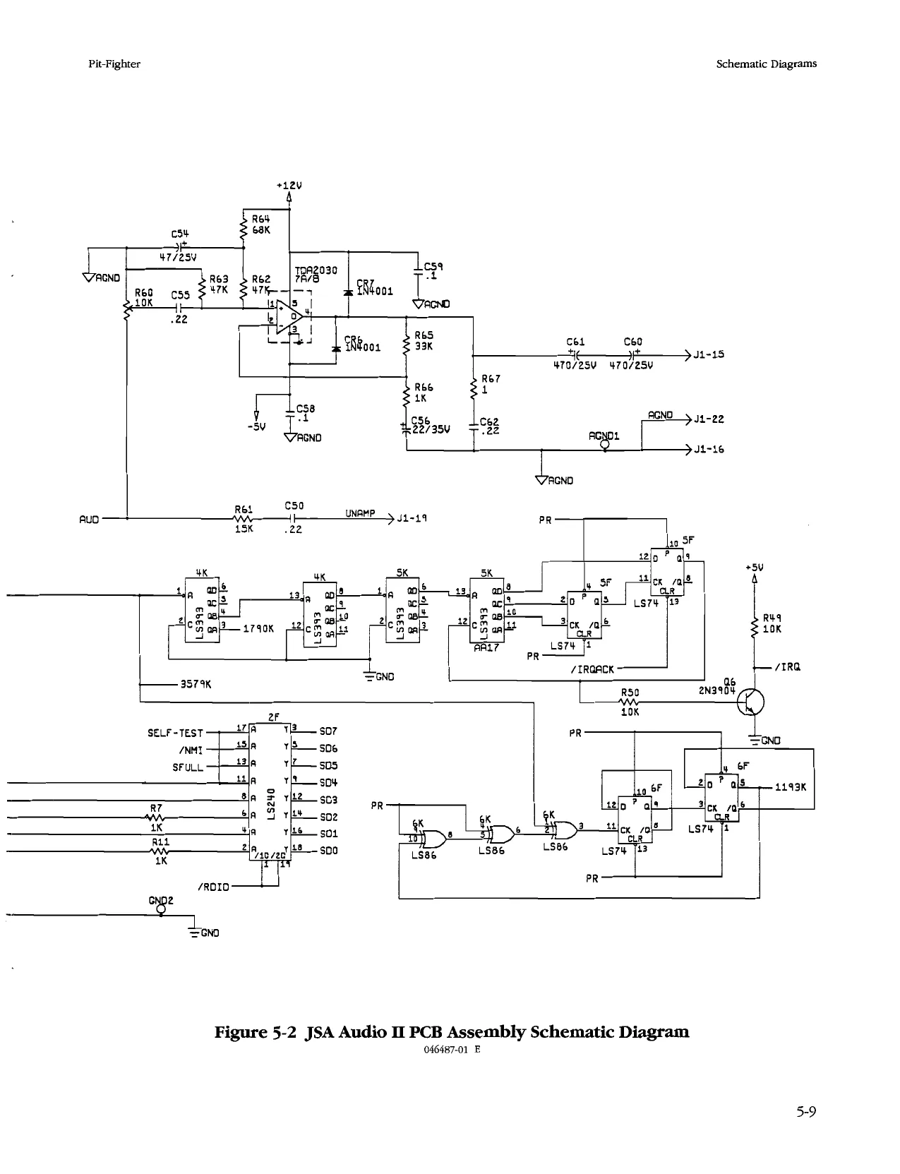
Pit-Fighter Schematic Diagrams
R33
Figure 5-2 JSA Audio Il PCB Assembly Schematic Diagram 046487-01 E
5-13
This page reads as a drawing: its text was drawn rather than typeset, and comes out in fragments. See the original scan.
This page reads as a drawing: its text was drawn rather than typeset, and comes out in fragments. See the original scan.
Schematic Diagrams Pit-Fighter
N O T E S
5-16
fe GAMES
Date:
Statistics Screen
Left Coins:
Right Coins: 0 Player Minutes; 1 Player Minutes: 2 Player Minutes: 3 Player Minutes: Sessions:
New Games:
Continued Games:
New (Game) Mins: Cont. (Game) Mins:
Error Count:
Total Credits:
Avg Time/Credit: Avg Time/New Game: Avg. Time/Cont. Game: ___ Location:
Histogram Screens
Histogram 1: New Games in Seconds
0-39
40-59 —— 60-79 ——_ 80-99 ——_ 100-119
120-139 __
140-159 ___
160-179
180-199 __
200-219
220-239
240-259
260-279 __
280-299 __
300-319 ___s
320-339 __
340-359
360-379 __
380-399 __
400 & up Histogram 2: Continuatioas in Seconds
0-39 = 40-59 — 60-79 — 80-99 — 100-119
120-139 __
140-159 ___
160-179
180-199
200-219 ___
220-239
240-259
260-279 __
280-299
300-319 __
320-339 ___
340-359
360-379 __
380-399 ___
400 & up Histogram 3: Sessions in Minutes
0-2
3-5 —.
9-11 —
12-14
15-17 —
21-23
24-26
27-29
33-35 —— 36-38 — 39-A1 — 42-44
45-47 —— 48-50 —
51-53 —
54-56
5S7&up __
This page carries no recoverable text. It is a drawing or a photograph. See the original scan.