Gran Trak 20 TM-004
Gran Trak 20 (Atari, 1974) · Technical Manual · 26 pages · 36 sections · original scan
Aid tddd Sb A wt
OPERATING
AND MAINTENANCE MANUAL
A ATARI
Innovative
leisure
14600 WINCHESTER BOULEVARD, LOS GATOS, CALIFORNIA 95030 + TELEPHONE (408) 374-2440 - TELEX 357-488
mmoO@> TABLE OF CONTENTS
Introduction and Warranty Information Access and Basic Construction New Machine Set-up and Check-out . The Game Sequence a The Antenna and The Anti-static Modification . . Top Section Sub-Assemblies: Service Procedures ................20005 The Coin Door: Service Procedures . @ Coin Acceptors ... @ Rejector Linkage Electronics Tray Sub-assemblies: Service Procedures . . The Control Panel: Service Procedures . @ The Gear Shifter .... @ The Pedal Assembly @ The Steering Wheel Assembly . .
General Maintenance .................00005
Troubleshooting .......... 0000 eee eee eee
LIST OF ILLUSTRATIONS
Figure Subject
1 GT-20; Side View 2 GT-20; Front View
- General Illumination Lamps
- Coin Door
- Gear Shifter
- Pedal Assembly 7 Steering Wheel Assembly
- T.V. Monitor Adjustments
- T.V. Monitor Schematic
- Wiring Diagram 11, Game Adjustments Location
- Coin Acceptor
- Electronics Tray Assembly
- Analog Board Schematic 15 a.,b. Digital Board Schematic
© ATARI, INC., 1974
A. INTRODUCTION AND WARRANTY INFORMATION
Gran Trak 20 isa coin operated video amusement device which simulates the experience of driving a high speed race car around a difficult track. All the machine controls both sides (steering, gear shift, like those of a real car. The electronics of this game are solid state for long life and low maintenance. The mechanical assemblies (steering, gear shifter and pedals) have been designed modularly for easy removal and servicing. However, as with all devices mechanical or electrical, celerator_ and brakes) behave
there may be minor problems, /f a printed circuit board computer (PCB) fails within the warranty period, contact the distributor from whom the game was originally pur: chased for repair or replacement instructions. Any PCB repair attempted by anyone other than authorized Atari Service Center personnel will void the PCB warranty. If the PCB fails after the one-year (from date of factory shipment) warranty period has expired, it will be repaired for a nominal parts and labor charge. Atari, Inc. warrants the T.V. monitor for a period of thirty days commencing the day of shipment from the Atari factory. If the monitor fails within the warranty period, immediately contact the distributor from whom the game was originally purchased for repair or replacement instructions. Any T.V. repairs other than replacement of fuses or minor adjustments attempted during the warranty period by anyone other than authorized Atari Service Center Personnel will void the T.V. monitor warranty. If the T.V. monitor fails after the warranty period has expired, it may be returned to the distributor where it will
be repaired or replaced for anominal parts and labor charge,
or it may be taken to any competent T.V. repair shop.
B: ACCESS AND BASIC CONSTRUCTION
Three openings: Coin door, rear door and a swing-out front control panel—provide convenient access to all subassemblies and adjustment points. Opening the coin door exposes all the coin handling equipment—the coin acceptors and rejector linkages, the coin counter and the coin box. The rear door is used to service the T.V. monitor, the pedal assemblies and the components mounted to the cash deck the PCBs, the transformer and the fuses. An interlock switch is mounted to the cash deck and turns off the entire machine when the rear door is opened The interlock switch protects the operator from accidental shock, so it must always be kept in perfect working order. If you need to test or adjust the machine with the rear door open, place the interlock switch in the closed or “on’* position by pulling out the white actuator shaft, All the major sub-assemblies have been designed modu larly for easy servicing or replacement. The control panel, the pedal assemblies, the Gran Trak 20 computer and the T.V. monitor can each be removed after the wiring and release bolts have been removed.
C: NEW MACHINE SET-UP AND CHECK OUT PROCEDURES
Before turning this machine on, inspect it carefully for any damage which may have occurred during shipping. As each new Gran Trak 20 leaves the factory, every component and sub-assembly is carefully checked for proper operation and adjustment, However, since parts may have been damaged or adjustments changed during shipping, the following check out procedure must be re peated prior to placing the machine on location.
- With the machine unplugged, open both access doors and carefully inspect both the exterior and interior of the machine for any obvious shipping damage to the cabinet or internal components and sub-assemblies. If any such damage is discovered, contact the carrier immediately. Then contact the distributor from whom the game was originally purchased for repair or replacement instructions.
- Inspect the interior of the machine more carefully looking for broken or disconnected wires, sub-assemblies pulling loose or not firmly mounted and any foreign objects shorting electrical connections. Pay particular attention to the connections to the T.V. monitor, the control panel and the coin door. Also make sure that the PCB edge connectors and the fuses are firmly seated. Note: The plug is located inside the cabinet for shipping purposes, and should be fed through the 1%” hole located at the left lower bottom portion of the cabinet.
- Plug in the machine and if the rear door panel is off,
defeat the interlock switch by pulling out the white actuator
shaft. At this point the CRT (Cathode Ray Tube) should display the race track and the score after a short warm up time. Examine the CRT picture. It should be steady, sharp and exhibit the proper levels of brightness and contrast
- Insert several old and new coins into each coin acceptor. No genuine coin should be rejected. One coin in either acceptor should produce game credit (indicated by a small red light (LED) on the right side) and advance coin counter one digit. Pressing the right side start switch resets score and places one car at the start ine, Once the starter button has been pushed the insertion of another coin will not affect the credit circuit. Check for proper game sequence, making sure all aspects of the game (steering, gear shift, accelerator, brakes, score and track display) are functioning correctly. If you are not familiar with the game sequence for Gran Trak 20, read the game sequence analysis. To repeat performance check on left side, insert two coins in either acceptor (not at the same time since this would register as one coin) which should produce game credit (indicated by the LED on the left side of the control panel). Pressing the left side start switch resets score and places both cars at the start line. Repeat the right side performance check on the left side. Check to see that “crash” does occur between the two cars.
- Adjusting play time modifies crash mode. The play time is pre-set at the factory for approximately 2% minutes and should not be changed.
- Both doors (rear and cash) should open and close without binding, and both door locks should turn to the “locked” and “unlocked” positions freely.
- Check the rear door interlock switch to see that it turns off the machine when the door is opened.
D: THE GAME SEQUENCE
With the game plugged in and the rear door installed, the CRT will display the attract mode. The attract mode for Gran Trak 20 displays the race course and a stationary race car positioned where the last player ended, plus the score of the previous game (which should read 0). Coin insertion lights the credit light in the start switch button and the game commences when this button is pressed. At the point the score is reset to 0, the timer begins counting down from 78 by 2s, the car engine begins idling and is ready to be driven. The controls of the machine and the movement of the car image simulate those of a real car. Once accelerated, the car becomes increasingly difficult to stop the faster the car is moving. Turning the steering wheel causes the car to turn in the direction of rotation. The car will turn only while the steering wheel is being rotated The gear shifter works exactly like that of a real car. Use reverse gear to hack off of the pylons after a crash. Then shift into first, rotate the steering wheel to turn the car so it will continue in the proper direction and step on the accelerator pedal. Once the engine has rewed to its limit, shift into second and once the engine has revved to its limit, shift into third, The speed of the car will climb as you shift through the gears. Keep in mind, though, that the engine will “bog” down if you shift up too fast or start out in the wrong gear (2nd or 3rd).
Both the accelerator and brakes have only two positions:
on or off. When the accelerator is depressed, the engine will rev up. Stepping on the brake pedal will bring the car to a screeching halt and if the steering wheel is turned as the brakes are applied, the car will skid realistically. Points are scored only by passing the course check
points in the proper sequence as indicated by the arrows on
the CRT. The score is displayed in the pit area next to the game timer. If the car is driven into any of the pylons, or the other car, a crash will result. The crash is accompanied by a crash sound, uncontrolled spinning of the car during which time the car cannot be driven. As soon as the crash sound has ended, shift into first and continue driving the car in the proper direction. The game continues in this fashion for approximately 150 seconds at which point the controls become “dead” and the machine is reset to the attract mode Players are given an indication of their skill by matching their score (points) against the ‘rating card’ located at the lower right-hand corner of the glass covering the video display. This rating system is based on a game playtime of approximately one minute and forty-five seconds (as adjusted prior to shipment). The rating card reads:
YOUR SCORE 0-10 License Revoked 11-20 Backseat Driver 21-30 Good 31-40 Excellent Above 40 Real Pro
If game playtime is readjusted by the operator, this point/rating system is no longer valid and should be changed. International shipments of Gran Trak 20 are supplied with a blank card on which to copy the above rating card in local languages.
E: THE ANTENNA WIRE AND ANTI-STATIC MODIFICATION
An electronic latch circuit has been incorporated in the Gran Trak 20 computer. One function of this circuit is to turn off or prevent game credit if a player tries to obtain free games by inducing a static charge in the machine. The antenna wire is an integral part of this system. When a static discharge occurs, an electric current is induced in the antenna wire. This impulse is transmitted through the antenna wire to the electronic latch circuit which turns off game credit and resets the computer to the attract mode. The antenna wire is a length of white wire approximately 12 inches long. One end of the antenna is connected to pin 17 of the PCB edge connector and the other end has been intentionally left not connected. The length of the antenna wire has been pre-adjusted by the factory to the overall optimum length, however some environments may require more or less critical adjustment.
Use the following procedures to replace the general illumination lamps, the plexiglass screen and bezel and to service the T.V. monitor.
- GENERAL ILLUMINATION LAMPS: Eight 6 volt lamps are mounted on a PC board behind the plexiglass screen to illuminate the Gran Trak 20 logo. To replace burned out lamps, reach in the rear door and unscrew the four lamp PC board mounting screws [#12, Fig. 1] and unplug the 2 wires which are attached to it at the plugs located in the upper right inside area of the cabinet. Re move the panel and replace burned out lamps with GE44 or GE47,
- PLEXIGLASS SCREEN: Use procedure #1 to remove the lamp PCB. Then remove the three wing nuts and carriage bolts (#27, 32 & 37, Fig. 1] which hold down the upper aluminum plexiglass screen retainer (#10, Fig. 1] and lift out the plexiglass.
- BEZEL: Use procedures #1 and #2 to remove plexiglass and the bezel [#8, Fig. 1] will lift out.
4, T.V. MONITOR: To remove the entire T.V. monitor assembly [#2, Fig. 1], remove the three carriage bolts [#40, Fig, 1] found on the top of the monitor frame and the four Phillips head bolts found on the sides. Do not remove the aluminum angle brace at the bottom. Disconnect the electrical connector to the T.V. and lift the monitor out very carefully. DISCHARGE THE SECOND ANODE BE- FORE SERVICING.
- T.V, MONITOR ADJUSTMENT: The T.V. monitor and Lengthening the antenna wire increases the sensitivity of the circuit; cutting the wire shorter decreases the sensitivity. If players are obtaining free games by inducing static charges in the machine, lengthen the antenna wire (add a piece of wire) by a few inches so that a lesser charge will turn off game credit. If you have problems with static charges accidentally turning off game credit during the progress of a legitimate game, try cutting the antenna shorter in increments of 1-2 inches. Try to cut only the minimum amount off the-antenna, otherwise players may be able to obtain free games. The anti-static modification may be tested during a game by touching the end of the antenna wire with your finger as the body usually has enough capacitance to actuate the electronic latch. If the game is shut off, the circuit is functioning correctly.
: TOP SECTION SUB-ASSEMBLIES: SERVICE PROCEDURES
its adjustment controls function like any normal T.V. set with the exception of the sound which is adjusted on the PCB (see page 5). The monitor is serviced through the rear door of the machine. See figure 8 on Page 16 for the locations of the following adjustments:
a, Brightness: Adjust the brightness before the contrast. Adjust so that the CRT background is as dark as possible.
b. Contrast: The contrast is adjusted so that the CRT images are as bright as possible against the pre-adjusted dark background without being blurred. c. Vertical Hold: Adjust only if the picture appears to be rolling up or down the screen. Adjust for a stable centered picture.
d. Horizontal Hold: Adjust if the picture is slightly off center horizontally, if the images appear warped or if the picture is broken into a series of diagonal lines.
e. Vertical Size: Adjust only if the top and bottom of the race course is cut off from the screen or if there is too much distance between the edge of the course and the edge of the screen, which will appear as an extra set of
horizontal dotted lines on the top and bottom of the CRT f, Vertical Linearity: Change this adjustment only if the g. The Yoke: The yoke should never need adjustment un
display. Adjust for maximum picture size.
top of the picture seems compressed. g. The Yoke: The yoke should never need adjustment unless the adjusters have been tampered with or the machine damaged. {f yoke adjustment is indicated, adjust both
yoke rings simuftaneously for optimum centering of the race course on the CRT.
h. The A.C. Voltage Switch: Set this h to the 115 Volt position (’"115” visible on the switch) if the machine is connected to a 115 Volt source. The T.V. monitor will not function if this switch is misadjusted.
- The T.V. Monitor Fuses: Two 8/10 Amp. 125 Volt Slo-Blo fuses (313 3AG) protect the T.V. monitor from electrical overload. Replace blown fuses only with those which have the above rating. NOTE: The T.V. is not fused by the fuse on the electronics tray.
G: THE COIN DOOR: SERVICE PROCEDURES
All coin handling equipment is accessible through the front door. To collect the coins, open the door, remove the coin box and record the meter reading. The Gran Trak 20 is equipped with two coin acceptor assemblies so the entire machine will not be out of service if one acceptor is malfunctioning Please keep in mind that proper adjustment and lubri cation of the coin handling equipment will help minimize your service calls.
1, THE DOOR LOCK: The lock cylinder can be withdrawn and replaced after the rear retaining nut and the lock cam are removed. If the coin door does not fit tightly or the lock does not turn freely, try bending the lock cam slightly with a pair of pliers. NOTE: The lock cylinder should be lubricated once every three months or so with graphite or WD.-40.
2. THE REJECT LINKAGE: A separate button operates
the wiper lever of each coin acceptor. When this is pressed, the wiper lever [#17, Fig. 12d] of the coin acceptor is operated which should dislodge any coins “stuck” in the acceptor, The rejector buttons cannot be removed. NOTE: Lubricate the rejector linkage with silicone grease when you receive the machine and thereafter at approximately six month intervals.
3. THE COIN MICRO SWITCHES: To remove a malfunc
tioning micro switch, unscrew the two retaining screws [#1, Fig. 12a], record the wire positions and pull off the slip-on connectors.
4, THE COIN ACCEPTORS: The coin acceptor can be removed for servicing after the retaining screws (#2, Fig. 12b] have been removed.
- ACCEPTOR ADJUSTMENT AND MAINTENANCE:
ADJUSTMENT: All coin acceptors leave the factory adjusted for maximum performance. However, if more critical adjustments are necessary or if the unit has been completely disassembled for service, the following adjust: ment procedure is suggested: (These tests and adjustments are performed with the acceptor in a vertical position on a level surface [the rest
Position] .)
KICKER AND SEPARATOR
1, Set the unit with the back of the acceptor facing you in the test position.
- Loosen the screws holding the kicker [1} and the separator [3] and move both the kicker [2] and the separator (4] as far to the right as they will go. Tighten the screws.
- Insert. several test coins (both old arid new) and note that some are returned by striking the separator.
- Loosen the separator screw and move the separator a slight amount to the left. Tighten the screw.
- Insert the test coins again and, if some of them are still returned, repeat Step #4 until all the coins are accepted.
- Loosen the kicker screw and move the kicker as far to the left as it will go. Tighten the screw.
- Insert the test coins and note that some are returned.
- Loosen the kicker screw and move the kicker a slight amount to the right.
- Insert the test coins again and, if some are still returned, repeat Step #8 until all the coins are accepted.
- Be sure that both screws are tight after the adjustments have been made.
THE MAGNET GATE
1, Set the acceptor with the front of the unit facing you in the test position.
- Turn the magnet gate adjusting screw (#12, Fig. 12d and #3, Fig. 12a] out (counterctockwise) until none of the coins will fit through.
- With a coin resting in the coin entrance of the acceptor (#4, Fig. 12c], turn the adjuster in (clockwise) until the barely passes through the magnet gate. 4, Test this adjustment using several other coins (both old and new) and, if any of them fail to pass through the magnet gate, repeat Step #3 until all of the coins are accepted.
- Fix the magnet gate adjusting screw in this position by tightening down the magnet gate screw lock nut.
ACCEPTOR MAINTENANCE: Depending on the environ: ment in which the acceptor is used, periodic preventative maintenance should be performed. The mainplate [#5, Fig. 12d] may be cleaned with any non-abrasive household cleaner. Rinse and dry thoroughly to remove deposits and film. Remove all metal particles from the magnet by guiding the point of a screwdriver along the edges of the magnet. Remove the transfer cradle (#9, Fig. 12d] and clean the bushing and pivot pin. A pipe cleaner is an effective cleaning tool. Apply powdered graphite or pencil lead to the pin and bushing and reassemble. Spray the entire unit lightly with WD-40 or a similar silicone lubricant.
H: ELECTRONICS TRAY SUB-ASSEMBLIES: SERVICE PROCEDURES
(PULL OUT THE POWER CORD WHILE PERFORMING PROCEDURES 1-4.)
1, FUSE REPLACEMENT: First remove the AC protective cover and replace the bad fuse with a Slo-Blo fuse rated at 3A, 125 Volts (313 3AGC).
- TRANSFORMER REPLACEMENT: To remove a mal functioning transformer remove the AC protective cover, record all wire colors and their positions, unsolder the wiring and unscrew the retaining screws. NOTE: When installing the new transformer, be sure to reconnect the chassis ground wire (lugs fastened with wood screws that mount the transformers to the wood electronics tray).
- INTERLOCK SWITCH: To remove the switch, pull off the push-on connectors, squeeze in side tabs on the switch and push it through the mounting bracket.
4, PRINTED CIRCUIT BOARDS: To remove the PCBs, disconnect the PCB edge connectors, remove the four re taining screws and carefully lift out the board. PCBs are extremely fragile and require very careful handling.
- SMALL PCB ADJUSTMENTS:
a. Volume: This adjustment is made by means of smalt blue trim pots marked “volume” A and B, Adjust the volume to the preference of the location but keep in mind that the machine will sound louder with the door off.
b. Play Time: This adjustment is located near H9 and adjusts both the total play time and the crash time period. Playtime is pre-set before shipment and should not be adjusted due to interrelationships with other game functions (i.e., crash time, rating system) If you have the following symptoms, recalibration of one or more of the cemented pots is indicated and you must return the board to your distributor:
- If the car seems to move too slowly
- If the sound of the engine rewing up is distorted
- If the sound of the car coming to a stop with the brakes applied (the “screech” sound) is distorted.
|: THE CONTROL PANEL: SERVICE PROCEDURES
1, CONTROL PANEL: To service the rear of the control panel, remove the four wing nuts and the panel will swivel out and be held by the chain. To remove the control panel completely, disconnect wiring and chain and lift out panel assembly. Note wire color and position for reconnection.
- GEAR SHIFTER ASSEMBLY: To remove gear shifter from the control panel, first swivel out the contro! panel as per procedure #1. Then record the wire colors and their positions for later reference and pull off all the slip-on connectors to the shift switches. Shift assembly can be withdrawn through the front of the contro! panel after the four retaining screws have been removed. To open the gear shifter assembly, remove the four machine screws [Fig. 5] while holding the housing halves together with your fingers. Split the housing halves carefully so internal parts will not spring out and become lost. With the housing halves separated, the gearshift rod (#3, Fig. 5}, spring (#7, Fig. 5], ball [#15, Fig. 5], detent (#4, Fig. 5] and switch actuators (#5, Fig. 5] will all be accessible. NOTE: When re-assembling the unit, lubricate the ball with a small amount of silicone grease and be sure that you replace the housing screws the same way they came out.
- THE PEDAL ASSEMBLY: The pedal assembly must be removed to replace the brake and accellerator switches. Reach in the rear door and remove three nuts (#21, Fig. 6]. From the front of the machine, grasp the protruding lip of the pedal assembly and pull out the entire unit. To replace switches [#13, Fig. 6] or pedals (#2, Fig. 6], remove the four pedal retaining screws and lift off pedal. Be sure to record all wire colors and positions before removing them from the switches.
- STEERING WHEEL ASSEMBLY: To service or remove steering wheel assembly, swivel the control panel out as per Procedure #1. To replace the wheel, remove the shaft end nut (#14, Fig. 7]. Lift off the slotted tack ring (#16] and withdraw the steering wheel through the front of the con trol panel. If only the wheel needs replacement, remove the cap [#2] and the shaft [#4]. The cap will lift off when retaining screws [#6] are removed and the shaft can be disassembled when retaining nut [#9] is removed. NOTE When reassembling the unit, lubricate the bearings [#11 and #12] with a small amount of silicone grease and when reinstalling the shaft, be careful not to push out the rear bearing. Tighten shaft end nut. To replace the steering assembly PCB, remove shaft end nut and tack ring, The PCB can be replaced after the retaining screws [#5, Fig. 7] are removed. To replace the steering wheel bushing assembly, use procedure 4 to remove the steering wheel, then remove the six retaining screws which hold the backing plate to the control Panel, Withdraw the bushing assembly through the front of the panel
J: GENERAL MACHINE MAINTENANCE
Due to its solid state circuitry, your GT-20 will require very little maintenance other than periodic cleaning, fubri cation and T.V. monitor adjustment. The cabinet and plexiglass screen may be cleaned with any non-abrasive household cleaner. The coin acceptors, Fejector linkages and the lock cylinders should be lightly sprayed once every three months with WD-40 or a similar silicone lubricant. The T.V. monitor is adjusted only if the CRT picture is distorted or if the contrast or brightness are out of adjustment.
K: TROUBLESHOOTING PROCEDURES
The first step in any troubleshooting procedure is to correctly identify the observable symptoms of the malfunction. With these clues in mind, examine the areas of the machine which might cause these symptoms. It is helpful for troubleshooting purposes to isolate three areas:
1, THE T.V. MONITOR: Many T.V. problems can be recti
fied with proper T.V. adjustment. However, if the problem
persists or if the T.V. is undoubtedly malfunctioning, con: tact your distributor or remove the T.V, monitor and take it to a competent local T.V. repair shop. Complete T.V. Monitor repair manuals are available free of charge from the Atari Customer Service Department, 14600 Winchester Bivd., Los Gatos, Ca. 95030. Phone: (408) 374-2440/ Telex: 357-488,
- THE PCB COMPUTER: Most PCB malfunctions will not be within your scope to repair. If you can positively determine that your PCB computer has failed, contact the distributor from whom you purchased the game for repair ‘or replacement instructions. Please be aware that some symptoms which might appear as PCB malfunctions may be the result of improper T.V. monitor adjustment or misadjustment of the small blue trim pots located on the PCB. Do not attempt to repair the PCB yourself unless you have been specifically instructed to do so by your distributor. To do otherwise will void your PCB warranty.
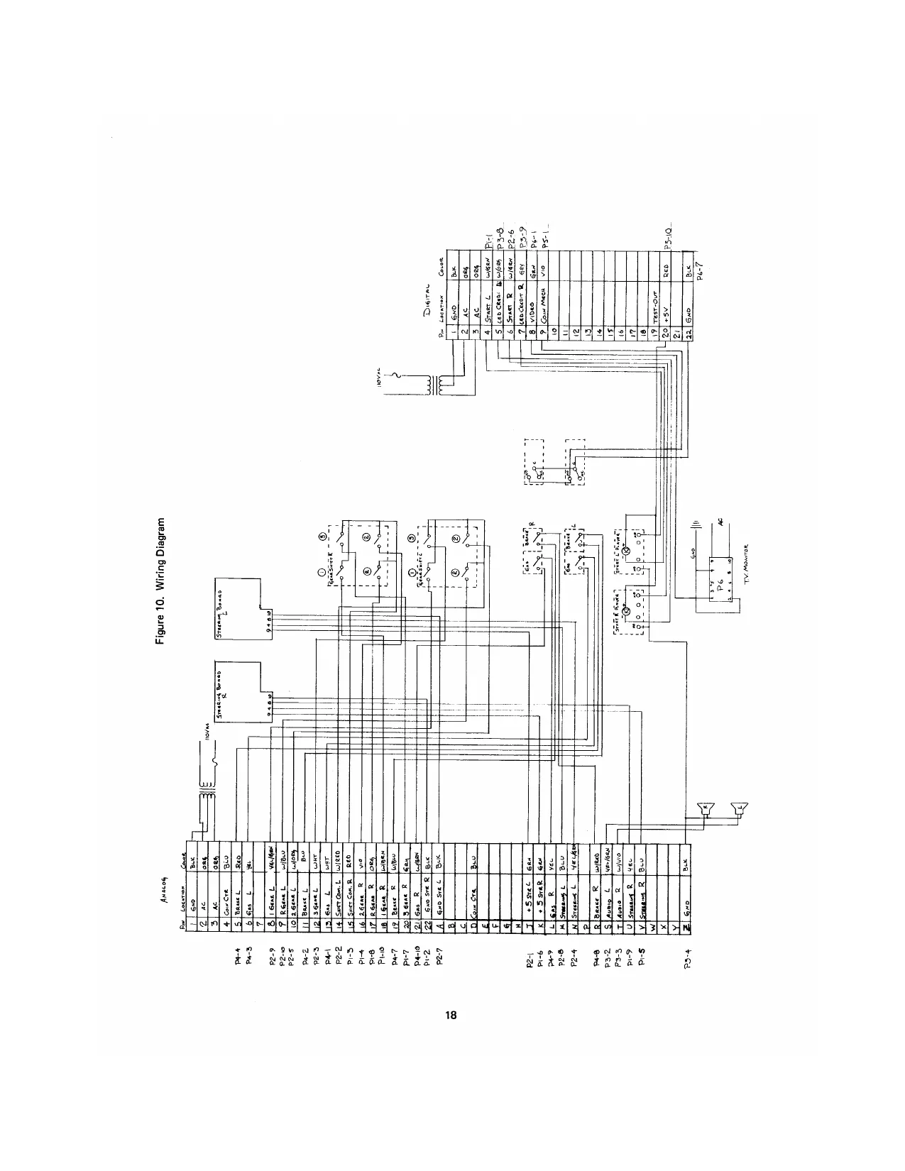
- THE WIRING HARNESS: For troubleshooting purpos: es, the harness includes the line cord, the fuse, the A.C. line filter, the transformers, the interlock switch, the antenna wire, the start and coin switches, the steering assembly, the gear shifter, the pedal assembly, the PCB edge connector, the T.V. monitor, the speaker and all the interconnecting lengths of wire. A wiring enclosure diagram of the wiring harness and associated components has been included at the end of this manual to aid in troubleshooting.
- SUGGESTIONS: Following are some specific instructions and suggestions for troubleshooting your Gran Trak
- To perform even the most simple troubleshooting procedures, you must have a VOM (Volt-Ohmeter) and, if possible a VTVM (Vacuum Tube Volt Meter) or digital voltmeter. It is also very helpful to have another GT 20 game (or a spare T.V. monitor and PCB) available for substitution purposes. For many problems, substitution may be the easiest way to troubleshoot the machine. For example, if you suspect a PCB malfunction, try substituting another and known-tobe-good PCB. If the malfunction disappears, the first PCB must have been the cause. Conversely, if the malfunction persists, the cause of the malfunction must be located in either the T.V. or the harness. The T.V. monitor can also be checked by substitution. Simply connect the game to a known-to-be-good monitor and if the malfunction is cleared up, the first monitor must
have been the cause. Harnesses must be checked by elimination, Substitute a known-to-be-good T.V. and PCB, and if the malfunction Persists, the harness and associated mechanical or electronic equipment must be at fault.
- T.V. MONITOR TROUBLESHOOTING: Some typical T.V. problems are distorted display, raster only or no video atall, If you do not have a raster (a raster is a lighted but blank T.V. screen with the brightness turned all the way up), begin checking the power supply to determine if the
T.V. is getting power. If the general illumination lamps of
the machine are lighted, at least you know that power is reaching the machine. If not, check your line cord, inter lock switch, fuse, etc. If it is A.C. powered, go around to the back of the machine and with the rear door open (and interlock switch defeated) listen for a hum emanating from the monitor. If there is a hum, the monitor is powered and you may have a defective CRT or similar problem. Another test (and one which can be performed in a noisy environment) is to measure the voltage between the T.V. fuses and ground, If Your voltmeter reads 110 volts or more, you know the monitor is powered. If not, check the fuses, the T.V. connections and the harness to see why power is not reach ing the monitor. If the T.V. is powered but still not func tioning, check the T.V. AC voltage switch which should be set to the "115" position ('"115" visible on the switch) if it is connected to a 110 volt line source. If you have the correct voltage after the fuses, but the monitor still will not function, you have two choices: 1) Remove the monitor and take it to a specialist, or 2) turn to the T.V. schematic (page 17) and start exploring the monitor with a VTVM and an oscilloscope. If you do have a raster, you must determine why there are no video signals being displayed on the screen, These video signals are generated by the PCB computer and enter the monitor through pin (#1) of the T.V. monitor connector.
- STEERING ASSEMBLY TROUBLESHOOTING: Four small red LEDs have been included on the small PCB to aid in troubleshooting the steering electronics. Mounted on the small steering assemblies PCB are two
phototransistors and two infrared light emitting diodes. The
phototransistors are mounted behind the tack ring in such a way that the slots in the wheel break up the light emitted from the diodes. This generates pulses which are used by the computer to determine how quickly and in which direction the wheel is being turned. The test LEDs on the small PCB will light whenever the infrared diodes are stimulating the phototransistors ( whenever the diodes are “shining” through the slots in the slotted wheel onto the transistors). To test the steering wheel assemblies, simply rotate the wheel slowly in both directions while watching the two red LEDs on the small PCB. If your steering assembly is O.K., both LEDs will flicker. 1 both of the LEDs fail to light (or remain {it constantly) while wheel is being turned, you definitely have a malfunction before the main PCB, which may be either in the wiring harness or in the steering assembly PCB.
7, TROUBLESHOOTING BY SYMPTOM:
a. No Power: Check for correct line voltage and if O.K. then check the fuse on the electronics tray, interlock switch and the transformer primaries.
b. No T.V. Picture: Check for power as per procedure #1 (NO POWER) and if O.K., check T.V. connector and T.V. fuses. Measure voltage at T.V. fuses (should be 110 VAC) and if O.K., replace the T.V, monitor.
c. T.V. Raster Only: Check the harness and especially the PCB edge connector. If O.K., check the T.V. as per the special test under “'T.V. Troubleshooting”. Or check T.V. or PCB by substitution.
d. T.V. Picture Rolls: Adjust the T.V. vertical hold and if the rolling persists, check the T.V. or the PCB by substitution,
e. T.V. Picture Is Wavy: Adjust the T.V. horizontal hold and if the problem persists, try replacing the transformer (in the T.V. monitor itself).
f. T.V. Picture Is Broken Into Diagonal Lines: Adjust the T.V. horizontal hold and if the problem persists, check the T.V. or the PCB by substitution.
g. No Game Credit: Check the coin switches, the start switch, the harness and the positions of the PCB slide switches. If the problem persists check antenna wire and try substituting a new PCB.
h. No Game Start: Check the coin switches, the start ‘switch, the harness and replace the PCB if necessary.
i. Game Shuts Off Accidentally: Try cutting the antenna wire shorter in increments of 1-2 inches.
i. Game Credit Shuts Off or Picture Shrinks: Check the line voltage with your VOM and be aware that a large motor starting up (i.e, an air conditioner) may drop the tine voltage. Check to see that machine is firmly plugged in. If the problem only occurs at certain times of the day (especially at dusk), your trunk line voltage may be dropping.
k. No Audio: Check the volume controls, speaker connections and for 20 volts. If the problem persists, test the speaker and if the speaker is O.K. try replacing the PCB. |. Game Sequence Incorrect, Parts of The Race Course, Car, Score or Timer Missing or Distorted: Replace the PCB or check for proper power supply as described in “Troubleshooting the Power Supply.”
m. Car Will Not Steer or Turns in One Direction Only: Check PCB LEDs as per procedure on page 7 and if O.K., then replace the PCB computer. If LED test is O.K., check
steering harness and connections and for foreign matter in steering assembly. Replace steering PCB if necessary. n. No Brakes: Check brake switch and wires from brake pedal switch to PCB. If O.K., replace the PCB.
©. Brakes All The Time: Check brake switch for foreign material and/or shorting terminals,
p. No Accelerator: Follow procedure 14 for”NO BRAKES". q. Accelerator All The Time: Follow procedure #15.
+. All Four Gears Dead: Check connections and wires from gearshifter to PCB and if O.K., replace the PCB.
s. One, Two or Three Gears Dead: Check the connections and harness of the malfunctioning gear(s); check the shift ‘switch(s)for the malfunctioning gear(s). If problem persists, replace the small PCB.
- —— 44000 @e) Lust of MATERIALS. [oe ernantove fon | Beseerreu Pa a ZT BT
Figure 1. GT-2 pe se ie ea oo a aaa, PS
| pe | mma | ee |
aerate —[ teens aasemaer $ (aber —[ 7 [ower aaseeee Sissies tH ensebeesrecetbay
| 51 | 25isie —| | Hacaae seceniae |
ot See Pees B gauseton [© [prea azaae Bl Sate | + anata eas era OP It | 001520 1 ELE GLASS RETAIN TM
| te LaSetbES | 1 cone | aero |
Te | cosa —| 1 loeecme Co
| A | i | ee |
1 |[cobsaa-ce | 1 | Beicae? Ti eevee, Clas fe | eosess | face te eens rt Seesae-01 ea, Pi ae aR TEP
| fet | ee | ee ae | = |
is -seosea —{ rena bor Sisacol Set cossere | 6 (ae areas Br woos? setsar| = (eee — Game [#o aseas Sek + tena: Dace Donne (es fanse rezrel 1 (cece (ear Com] Ae Ei
| Ee [peed | Deana || wisn | ar Br. Brea Me |
Spee te eea te ea ae nee ae £7 | esse cies | eo wasn FETT Ba POTN By | oa Pe os 12 WHvEE ar tae OT 25 (face (edias le weg net See Se aes A me Pye a Sp les eau o fonawn oe See pear a twotauh eee SE ELE & lene teens, won ca, So leiss eave tit -{aeeat SuEeEG. wat bas Seo Fe nccol 9 |eceow ney bacaat soe ata,
| Sr | laa | fics (i | lace teeence ae ee aan |
Bo eS ees eine Bee 37 [irs ferwios| 2 [Seam wens, 292s BB ca late Se tateal ts [aca mae ab Be hs Ss late ree ee oe
fenay eons SCHEMATIC DiAGRAMS Ramee
Alors: (husssss MRNAS SHEED. QS Cusmions (17249) To BE MEASSEMBLED To GLAS ()74 7) Aes SPREE Peat OE a seus
QM ArHGH Pees Eu0 oe Coans (wor Sronal) Yo Page AssEmBLY, (74.5), WOR Se Ge a TRAY, Us Ome ecew (1700424) $ Ose LAP WAGER, FEMS).
Figure 2. GT-20; Front View
sdwe] uoneusuny| ex2UeD “g ainBiy
(rong 9) ‘onal md 290° Gorey) Fa ae
(spray "want We #8)
W
Item PartNo. Qty. Description
1 001735 1 Frame, Door and Coin Mech Frame Assy
2 001597 2 Weldment, Coin Guide 3 A001591 2 Weldment Coin Switch 4 83029 1_ Lock, Cash Door with Cam #001448 5 80106 2 Switch Cherry 6 75800 4 #4-40 x 3/4” PH Mach Screw 7 78829 = #8/32 x 1/4” PH Mach Screw
8 001779 1 Graphic Plate, Trak 10, Silk Screen
9 75412 4 1/8” Pop Rivets 10 75832 4 = Screw, Socket, Head Cap, 6/32 x 1/4” 11 75420 4 Screw, Mach., Pan Head, 6/32 x 3/16 12 75102 8 Washer, #6 Flat 13 75101 8 Washer, #6, INT. Tooth Star i 14 001593 2 Coin Plate Rigen. sino 15 758314 Washer Int. #8 Star
16 83286 2 Coin Acceptor, without frame or switch
POLES SNE there. any secon mer uo, Saoi-seee-
PARTNO. QTY. DESCRIPTION 000608 000609 000610 000611 000628
83241 80011 75102
75163 75-2412S/75811 72-1608S/75801
76-11375/75407 83268 83298 Ref H-Shift Assy (3201-3539) RasNn
ROO ARS
AIR Shift Housing (3201-3524 D) Handle Assy (3201-3535) Shift Detent (3201-3525 B) Shift Rivet (3201-3562)
Spring, Assoc. Spring Co (CO360-032-1000M) Switch, Cherry (G18-04A) Washer, Flat #6, Reg Pattern
Washer, Flat #4 Reg Pattern Screw, mach, Rd. Hd, Phil #4-40 x 3/4 Ig. Screw, mach, Pan Hd, Phil #6-32 x 1/2 Ig.
Ball, Steel, 3/8 diam., Bearing grade Silicone compound, Dow Corning #5 Clamp, Hose
Figure 5. Gear Shifter
@)
ITEM Searoasen " PART NO. A001631 000590 000591 000592 000593 000594 000597 175199 175409 178174 175102 001069 /80011 175811 175163 175162 175164 175302 178808 178131 178155 /83268 (84012 001662-01 178200 Figure 6, Pedal Assembly
ary. oe 3D WOWNRARANNMONNNNNNNNS DESCRIPTION Box Assembly Foot Pedal (3201-3533) Pedal Foot (3201-3534) Spring (3201-3550) Bumper (3201-3551) Stop Washer (3201-3552) Bearing Block (3201-3549) Screw, Mach., Pan Hd., Pt Washer, Fender 1/4 Screw, Mach., Pan Hd., #8 - 32 x 1 1/4” Lg. Washer, Flat, #8 Switch, Bracket Switch, Cherry (G-18-04A) Screw, Mach., Rd. Hd., Phi Washer, Flat, #4 Washer, Lock, #4 Nut, Hex, #4-40 Screw, Wood, Rd. Hd., Phil., #8 x 1/2” Lg, Screw, Mach., Pan Hd., Phil., #1/4 - 20 x Washer, Flat, #1/4 Nut, Hex, 1/4-20 Silicone Grease Compound #5 Contact Cement Harness, Foot Pedal Screw, SM, #6 x 1/2 La.
#4 - 40 x 3/4" Lg.
Lg. #1/4 - 20 x 1/2" Lg.
amuse LLL.
ans
O
were: Apr UAT FILM oF SIUCOUE eeeieE SS coum (oR ea, Cu AREAS LECTED. (TEM)
| en | ITEM | PART NO. | QTY. | DESCRIPTION |
| 1 | 000598 | Ref Steering Wheel Assy (3201-3803) | ||
| 2 | 000599 | 1 | Cover (3201-3543) | |
| 3 | 000605, | 1 | Housing (3201-3645) | |
| 4 | 000606 | 1 | Shaft (3201-3644) | |
| 5 — 73-1206/75822 | 2 | Screw, Drive, Phil Hd, #2 x 3/8 Lg. | ||
| 6 | = 72-7512/75804 | 3 | Screw, mach, Fil. Hd, Phil #1/4-20 x 3/4 Lg. | |
| 7 | 4000607 | 1 | Printed Circuit Assy. | |
| 9 | 75409 | 2 | Washer, Fender, 1/4 | |
| 11 | 76-042020/83236 | 1 | Bearing, Thompson (20L20-F) | |
| 12 | -76-041010/83242 | 1 | Bearing, Thompson (10L10-F) | |
| 13 | 78-40101/83243 | 1 | Steering Wheel ('“500", P/N 82-2231) | |
| 14 | 75-945N/75221 | 1 | Nut, #1/4 - 20, Nylon Lock | |
| 15 | -72-9580/75198 | 1 | Screw, mach, Truss Hd, Slotted #1/4-20 x 5 Lg. | |
| 16 | 000616 | 1 | Hub Light | |
| 17 | ——75-056/75189 | 1 | Washer, 1/4” int. tooth, starlock | |
| 18 | 83268 | A/R__ | Silicone Grease, Compound #5 |
Figure 7. Steering Wheel Assembly
Figure 8. T. V. Monitor Adjustments VIDEO INPUT i ee
AND POWER RS
CONNECTOR CONTRAST SRIGHTNESS HOLD HV, RECT
Py
RASTER
CENTERING
RINGS
CONTROL BRACKET
__, 8 LOCATION xm-700
PLUG IN
CIRCUIT BOARD
a6 REGULATOR VOLUME CONTROL (NOT USED) XM—700 CHASSIS REAR VIEW
7. stdin
wat eae Bak A
Figure 9. T.V. Monitor Schematic Diagram
This page is a drawing, shown as the original scan.
This page carries no recoverable text. It is a drawing or a photograph. See the original scan.
Figure 12b Figure 12a
Figure 12¢
COIN SWITCH RETAINING SCREWS COIN ACCEPTOR RETAINING SCREW MAGNET GATE ADJUSTER COIN ENTRANCE COIN SWITCH WIPER LEVER TRIP WIRE a NOW
Figure 12, Coin Acceptor
ITEM DESCRIPTION
KICKER SCREW KICKER SEPARATOR SCREW SEPARATOR MAINPLATE ASSEMBLY GATE ASSEMBLY COVERPLATE ASSEMBLY RAIL CRADLE ASSEMBLY UNDERSIZE LEVER MAGNET ASSEMBLY MAGNET GATE ADJUSTER LOWER GATE PIVOT SPRING UPPER GATE PIVOT SPRING GATE PIVOT PIN WIPER LEVER SPRING WIPER LEVER WIPER Figure 12d
COIN ACCEPTOR (EXPLODED VIEW)
3]_sisiogy a 7
4] Jo ABNESSS axa) SNe
shal] it
Sale alsialale| Eaee
Figure 13. Electronics Tray Assembly PART NO. 4001791 ‘4001793 4001796 001905 000871 001141 001623 55006** 30029 75102/75-016S, 75158 75200 78211/72-6620 77036/51-11833 77037/81-11822 80001 80002 80004 80030 80054/79-08322 83013/74-3608 83015 83042 83037/000268 001922-01 001922-02 4001920 A001921-01* A001921-02* 4001921-03 ary. wreee nen tye NN een eee re AIR AIR AIR DESCRIPTION P.C. BOARD ASSEMBLY, COMPUTER REVISION B, ANALOG P.C, BOARD ASSEMBLY, COMPUTER REVISION 8, DIGITAL,
HARNESS. COVER, TRANSFORMER LABEL, FOAM, DISC. POLYURETHANE TRAY ELECTRONICS TRANSFORMER AC POWER INTERLOCK SWITCH WASHER, FLAT #6 SCREW, #8 x 3/4”, RD. HD., PHIL., SMS ‘SCREW, SM, PAN HD., PHIL., #6 x 1/2 LG. ‘SCREW, #6 x 1 1/4”, PAN HD., PHIL., SMS WIRE, 18 GAUGE, ORANGE WIRE, 18 GAUGE, RED. FUSE HOLDER FUSE, 1 AMP, SLO-BLO COUNTER FILTER, POWER LINE TERMINAL, PUSH.ON (3/16' SPACER, 1/2", #6 POWER CORD, 8° CABLE CLAMP. BRACKET, SWITCH MOUNTING
CLEAT 17" CLEAT 7” HARNESS, VOLTAGE SELECTION SHORTING BLOCK, 95V SHORTING BLOCK, 110V ‘Install Shorting Block per Voltage Required. SHORTING BLOCK, 220V —**Use 001651 Transformer when available.
Figure 14, Analog Board Schematic