Lunar Lander DP-136-3rd-02B
Lunar Lander (rev 2) (Atari, 1979) · Drawing Package · 1 pages · original scan
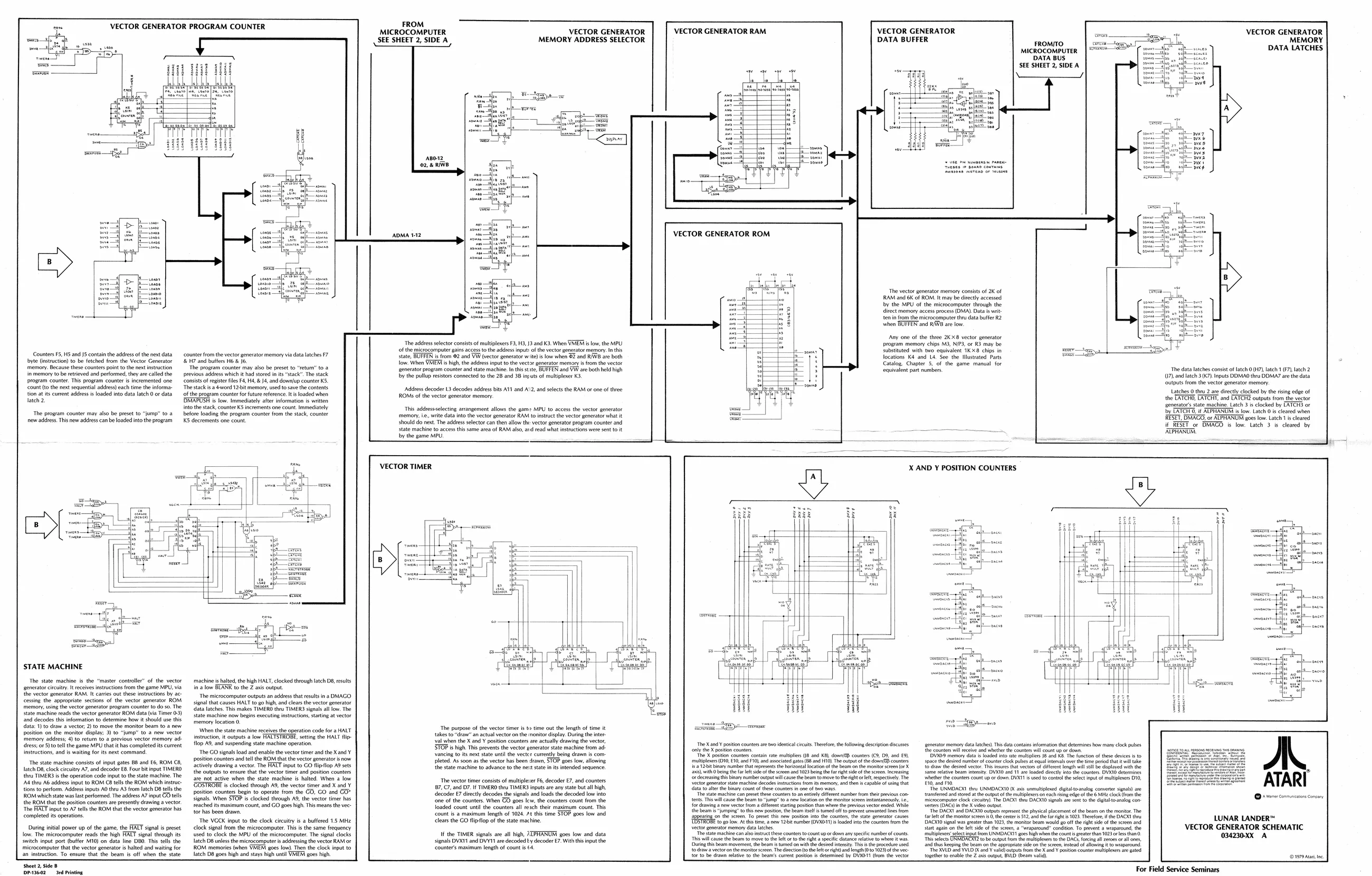
VECTOR GENERATOR PROGRAM COUNTER
Counters F5,H5 and J5 contain the address ofthe next data byte (instruction) to be fetched from the Vector Generator ‘memory. Because these counters point tthe next instruction in memory tobe retrieved and performed, they ae called the program counter. This program counter i incremented one count (to the next sequential addres) each time the informa tion at is curent address is loaded into data latch 0 or data lateh 2.
The program counter may also be preset to “jump” to a
new address. This new address canbe loaded into the program
‘counter from the vector generator memory via data latches F7
H7 and butters H6 & J6. ‘The program counter may also be preset to “return” to a previous address which it had stored in its “stack”. The stack Consists of register files FA, H4, & J4, and dowa(up counter KS
‘The stack sa 4word 12bit memory, used to save the contents into the stack, counter KS increments one count. Immediately
‘of the program counter for futute reference. Its loaded when DMAPUSH is low. Immediately after information is written
before loading the program counter from the stack, counter KS decrements one count
STATE MACHINE
‘The state machine is the “master controller” of the vector ‘generator circuitry. It receives instructions from the game MPU. via the vector generator RAM. It caries out these instructions by ac: cessing the appropriate sections of the vector generator ROM ‘memory, using the vector generator program counter to do so. The sate machine eads the vector generator ROM data (va Timer 03) And decodes this information to determine how it should use this data: 1) to draw a vector 2) to move the monitor beam to a new
position on the monitor display; 3) to “jump” to a new vector
memory address; 4) to return to a previous vector memory ad- ‘dress; oF 5) to tell the game MPU that it has completed its current instructions, and is waiting for its next command,
‘The state machine consists of input gates BB and E6, ROM C8,
latch DB, clock crcutey A7, and decoder 8. Four bt input TIMERO tions to perform. Adress inputs AO thru A3 from latch D8 tells the ‘The HALT input to A7 tells the ROM that the vector generator has
thru TIMERS isthe operation code input tothe state machine. The [Ad ty A6 address input to ROM CB tells the ROM which instruc
ROM which state was last performed. The address A7 input GO tells the ROM that the position counters ae presently drawing a vector.
completed its operations
During initial power up of the game, the FACT signal is preset love, The microcomputer reads the high HAUT signal through is ‘witch input port (buffer M10) on data line DBO. This tells the ‘microcomputer thatthe vector generator i hated and waiting for
[Ls instruction. To ensure that the beam is off when the state
machine i halted, the high HALT, clocked through latch D8, results ina low BLANK to the Z axis output. The microcomputer outputs an address that results in a DMAGO signal that causes HALT to go hish, and clears the vector generator ‘ata latches. This makes TIMERO thru TIMERS signals all low. The ‘state machine now begins executing instructions tating at vector memory location 0. ‘When the state machine receives the operation code for a HALT instruction, it outputs a low HACTSTROBE, setting the HALT flip flop A9, and suspending state machine operation. ‘The GO signals load and enable the vector timer and the Xand Y position counters ad tell the ROM that the vector generator snow actively drawing a vector. The FAT input to GO flipflop A9 sets the outputs to ensure thatthe vector timer and position counters are not active when the state machine is hated, When a low ‘COSTROBE is clocked theough AB, the vector timer and X and ¥ position counters begin to operate from the CO, GO and GO* Signals. When STOP is clocked through AS, the vector timer has reached its maximum count, and GO goes high. This means the vec: tor has been drawn, ‘The VGCK input to the clock citcuity is a buffered 1.5 MHz clock signal from the microcomputer. This is the same frequency tused to clock the MPU of the microcomputer. The signal clocks latch D8 unless the microcomputer is addressing the vector RAM oF ROM memories when VMEMI goes low). Then the clock input to latch D8 goes high and stays high until VMEM goes high. sheet 2, side B (DP-136-02 3rd Printing ADMA 1-12 base
‘The address selector consists of multiplexers F3, H3, J3 and K3. When VATEM is low, the MPU ‘of the microcomputer gains access tothe address input of the vector generator memory. In this state, BUFFEN is from @2 and VW (vector generator wit) i low when 2 and RAW are both low. When VATE is high, the address input to the vector generator memory is fom the vector ‘generator program counter and state machine. n this tite, BUFFEN and VW are both eld high by the pullup resistors connected to the 2B and 38 inruts of multiplexer K3,
Adress decoder 13 decodes address bits A11 and 2, and selects the RAM or one of three ROMS of the vector generator memory.
This addressselecting arrangement allows the gam> MPU to access the vector generator memory, ie, write data into the vector generator RAM to instuct the vector generator what it should do next. The address selector can then allow th vector generator program counter and state machine to access ths same area of RAM also ard read what instructions were sen to it by the game MPU. VECTOR GENERATOR ROM.
‘The vector generator memory consists of 2K of RAM and 6K of ROM. It may be directly accessed by the MPU of the microcomputer through the direct memory access process (DMA). Data is wit ten in from the microcomputer thru data buffer RZ when BUFFEN and RIWVB are low.
Any one of the three 2Kx8 vector generator program memory chips M3, NIP3, of R3 may be substituted with two equivalent 1KX8 chips in locations K4 and L4, See the Mlustrated Parts Catalog. Chapter 5, of the game manual for equivalent part numbers. FROM. MICROCOMPUTER VECTOR GENERATOR | VECTOR GENERATOR RAM VECTOR GENERATOR ors = VECTOR GENERATOR SEE SHEET 2, SIDE A MEMORY ADDRESS SELECTOR DATA BUFFER TROMTO paler MEMORY microcomputer} S="—*" DATA LATCHES,
DATA BUS SEE SHEET 2, SIDEA
The data latches consist of latch 0(H7, latch 1 (F7), atch 2
- and latch 3(K7) Inputs DDMAO thru DDMA7 are the data ‘outputs from the vector generator memory. Latches 0 thru 2 are directly clocked by the rising edge of the TATCHO, LATCHT, and CATCH outputs from the vector enerator's state machine_Latch 3's clocked by CATCH of by CATCH, if ALPHANUM is low. Latch 0 is cleared when RESET, DMAGO, or ALPHANUM goes low. Latch 1 is cleared RESET or DMAGO is low. Latch 3 is cleared by ATPHANUM.
VECTOR TIMER
‘The purpose of the vector timer isto time out the length of time it takes to "draw’ an actual vector on the monitor display. During the inter: val when the X and Y positon counters are actually drawing the vector, ‘STOP is high This prevents the vector generator state machine from ad: ‘ancing tits next state until the vecter currently being drawn i con pleted. As soon as the vector has been drawn, STOP goes low, allowing the state machine to advance tothe nest state in its intended Sequence
The vector timer consists of multipleverF6, decoder E7, and counters 'B7, C7, and D7. If TIMERO the TIMERS inputs are any state but all high, decoder E7 directly decodes the signals and loads the decoded low into ‘one of the counter. When GO goes lew, the counters count from the loaded count until the counters all reach their maximum count. Ths ‘count is a maximum length of 1024 A¢ this time STOP goes low and <lears the GO fliflop of the state machine.
If the TIMER signals are all high, ZTPHARUM goes low and data signals DVXT1 and DVYT1 are decoded ty decoder E7. With this input the ‘counter’ maximum length of count i 4, X AND Y POSITION COUNTERS
toan teen te e aEEE Petty BY a
\1]
The X and ¥ postion counters are wo dential ccs Therefore, the folowing description dicuses ‘only the X poston counters The X postion counters contain rate multiplies (18 and KB), down counters (C8, D8, and E ‘multiples (010, £10, and FIO, and associated gates (88 and HID) The ouput ofthe dow counters iS 12bi binary number that presents the horizontal location ofthe Beam on he monitor seen (8X ‘swith being the fr left side ofthe sereen and 1023 being the fa ight side ofthe screen Increasing ‘or deceasing this binary number eutput wl cause he beam to move tothe ight ele respectively The ‘vector generator state machine decades nstuctons fom ts memory. and then s capable of wing that ata to alter the binary count of these counter none o 0 way The sate machine con preset these counters to an ently efferent number fom the peeviouscontents Ths wl cause the beam to jum to ane Toeton on the monitor sereennstataneauy te. for grawing a new vector fom a ciferent stating poston than where the previous vector ended. While ‘the beam 5 "jumping to ths new postion, the beam el ted at to prevent wanted ies fom ang onthe screen. To preset this new poston ito the counter, the state generator causes i To po low. At ths time, a new 12bie number (DVAD) loaded into the counter rom the ‘sector generator memory dat atches “The state machine can aso instruct thew counters o count up or down ay specific number of counts ‘This wil cause the beam to move to te Ito othe it aspect stance relative to whee twas. ‘Dring this beam movement the beam stared on wth the desired item. Tha the rocedre ed todraw a vector on the monior screen The decton (othe let or igh and Tenth (0 to 1023 ofthe ve tor to be drawn relative to the beams cltemt poston determined by DVAOT (rm the vector generator memory data latches) This data contains information that determines how many clock ples ‘the counten wl receive and whether th counters wl count up or down 'DV09 memory data is oaded into ate multiplies JB and KB. The function of these devices & to space the desired numberof counter clk pulses at equal ntevals ove the time ered that wl take to draw the desired vector Th lnures that vectors of ferent length wl stil be dpayed withthe Same relative beam intensity. DVRIO and 11a loaded drecty ito the counter: DVXIO determines wheter the counters count up or down DVXIT is used o conual the Selec input of multiplexes D1, E10, an Fo The UNMDACM thu UNMDACKIO K axis unmultpleed digtaltoanalog converter signals) ae trastrred and stored at the outpatofte multiplexers on each sing edge ofthe 6 Mie clock tom the Imicrocompater clock circuty) The DACKI tu DACKTO signals are sent tothe digtalteanalog con ‘eters (DACS in the X video Outpt The DAC! and DAKO outputs represent the physical placement of the beam onthe mont. The fart ofthe mentor screen 0 the center's 5312, he fright #1023. Therefore the DCX ty DDACKIO signal was grater than 1023, he monitor Beam would go off the ight sie of the Screen and start again on the let sie ofthe scien, 2 “wraparound” condition. To prevent a wraparound, the rmulopeve select input fem UNMDACKT goes high when the count grater than 1025 oss than 0 ‘Ths selects UNMDNCXTZ to be output tom the multlener 0 the DACs, forcing all zeroes ral nes, and thus keeping the beam onthe approanate side onthe sree, instead of allowing to wraparound The XVLD ad VLD and val outputs rom the X and ¥ poston counter multiples ae gated together to enable the Z at output BLD (beam vali). LUNAR LANDER™ VECTOR GENERATOR SCHEMATIC 034230XX A
For Field Service Seminars