Centipede Cocktail DP-188-1st-02B
Centipede (revision 4) (Atari, 1980) · Drawing Package · 1 pages · original scan
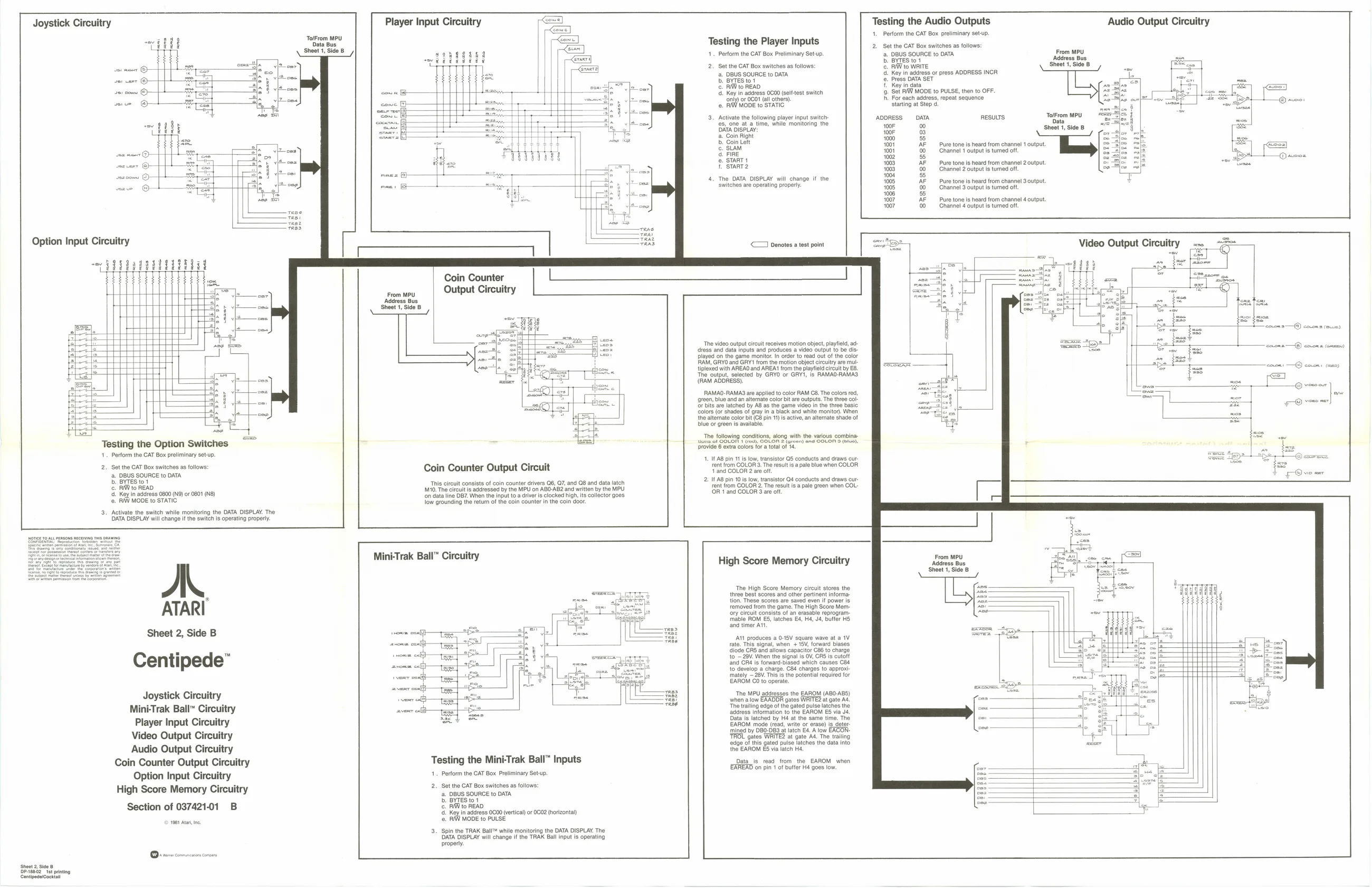
Joystick Circuitry
df
ser coms ©} Se sue ol _—#
sting the Option Switches
Tes
- Perform the CAT Box preliminary setup.
- Set the CAT Box switches as follows: ‘DBUS SOURCE to DATA BYTES tot
RWW to READ
|. Key in adress 0800 (N@) or 080 (NB) RAW MODE to STATIC.
- Activate the switch while monitoring the DATA DISPLAY. The DATA DISPLAY will change i the switch Is operating properly. : <r]
Coin Counter
fiom WU Output Circuitry sheet 1, Side'8
Testing the Player Inputs
- Perform the CAT Box Preliminary Setup
- Set the CAT Box switches as follows: ‘a. DBUS SOURCE to DATA . BYTES to1 ©. RAW to READ
- Key in address 0600 (sei-test switch ‘only or 0Ct (all others) ce. RAN MODE to STATIC
- Activate the following player input switch: fs, one at a time, while monitoring the DATA DISPLAY: a. Coin Right ’. Coin Left ©. SLAM
- FIRE ©. START 1 f. START2
4, The DATA DISPLAY will change if the ‘switches are operating property
Denotes a test point
Coin Counter Output Circuit
‘This circuit consists of coin counter drivers 06, Q7, and Q8 and data latch [M10. The circut Is addressed by the MPU on ABO-AB2 and written by the MPU ‘on data line DB7. When the input to a driver is clocked high its collector goes Tow grounding the return of the coin counter in the coin door.
A, ATARI
Sheet 2, Side B
Centipede”
Mini-Trak Ball” Circuitry Player Input Circuitry Video Output Circuitry Audio Output Circuitry Coin Counter Output Circuitry Option Input Circuitry High Score Memory Circuitry
Section of 03742101 B
‘Sheet 2, Sige 8 Destea2 tat printing (CentipederCoekta ‘The video output circuit receives motion objec, playtiod, ad- ‘dress and data inputs and produces a video output to be displayed on the game moniter. In order to read out of the color RAM, GRYO ang GRY trom the motion object circuitry are mut tiplexed with AREAO and AREA from the playfield circuit by E8, The output, selected by GRYO or GRY1, is RAMAQ-RAMAS (RAM ADDRESS),
RAMAO-RAMAS are applied to color RAM C8. The colors red, dren, blue and an alternate color bit ae outputs. The three Or bits are latched by AB as the game video in the three basic Colors (or shades of gray in a black and white moniton. When the alternate color bit (C8 pin 11) 's active, an alternate shade of blue or green is available.
‘The following conditions, along lotta of COLON | rou), COLON 2 provide 6 extra colors for a total of
- IF 8 pin 11 is low, transistor Q5 conducts and draws cur rent from COLOR 3. The results apale blue when COLOR ‘Vand COLOR 2 a off
- IAB pin 10's low, transistor Q4 conducts and draws cur: rent from COLOR 2. The result is pale green when COL- OR 1 and COLOR 3 are off
i-Trak Ball” Circuitry
Testing the Mini-Trak Ball” Inputs
- Perform the CAT Box Preliminary Setup. 2, Set the CAT Box switches as follows: ‘a. DBUS SOURCE to DATA . BYTES to1 ©. RAW to READ 4: Kay in adress 0000 (artical or 0002 torzontah fe, RUW MODE to PULSE
- Spin the TRAK Ball™ while monitoring the DATA DISPLAY. The DATA DISPLAY will change if the TRAK Ball input is operating property High Score Memory Circuitry
The High Score Memory circuit stores the three best scores and other pertinent informa. ‘scores are saved even if power Is ym the game. The High Score Memory onsists of an erasable reprogram. mable ROM E5, latches E4, H4, J4, buffer HS ‘and timer At,
Atl produces a 0-18V square wave at a 1V rate, This signal, when + 15V, forward biases diode CRS and allows capacitor C86 to charge to ~ 29V. When the signal is OV, CRS is cutoff land OR4 is forward-biased which causes C84 to develop a charge. C84 charges to approxi- ‘mately ~ 28V. This Is the potential required for EAROM C0 to operate
‘The MPU addresses the EAROM (ABO-ABS) when alow EAADDA gates WRITE? at gate Ad. ‘The trailing edge of the gated pulse latches the ‘address information to the EAROM E5 via J4. Data is latched by H4 at the same time. The EAROM mode (read, write or erase) is det ‘mined by DB0-DB3 at latch E4. A low EACON- TROL gates WRITE? at gate Ad. The trailing edge of this gated pulse latches the data into the EAROM 5 via latch Ha.
Data is read from the EAROM when EAREAD on pin 1 of buffer H4 goes low. Testing the Audio Outputs
- Perform the CAT Box preliminary setup.
- Set the CAT Box switches as follows: Audio Output Circuitry
a. DBUS SOURCE to DATA From MPU b. BYTES 101 ‘Address Bus . RAW to WRITE. esi 9Ig6 8:
- Key in address or press ADDRESS INCR @. Press DATA SET 1 Koy in data
- Set RIW MODE to PULSE, then to OFF. hn. For each address, repeat sequence starting at Step o ADDRESS DATA RESULTS, Tron MPU 100 00 100F 93 nae 4000 55
| 1001 | AF | Pure tone is heard from channel 1 output. |
| 1001 | (00 | Channel 1 output is turned of |
joo 55
| 1003 | AF | Pure tone is heard from channel 2 output. |
| 1003 | (00 | Channel 2 output is turned of |
1004 55
| 1005, | AF | Pure tone is heard from channel 3.output. |
| 4005 | (00 | Channe!'3 output is tumed oft. |
1006, 5
| 1007 | AF | Pure tone is heard from channel 4 output |
| 007 | (00 | Channel ¢ output is tured oft |
Video Output Circuitry
coven —O) covces (mun)
+ —@ coors (nao St oa oa
From MPU ‘Address Bus Sheet 1, Side B