Alien Syndrome
Alien Syndrome (set 4, System 16B, unprotected) (Sega, 1987) · Document · 10 pages · 9 sections · original scan
OWNER’S MANUAL
SEGA ENTERPRISES, LTD.
MANUAL NO. 4201-0001
CONTENTS
- HANDLING PRECAUTIONS ....0....cccceec eee cee eee ene e cence sneer eee nee eceeeeereeerieeneeseee 1
- PREVENTION OF COUNTERFEITING AND CONVERSION .
- PRECAUTIONS CONCERNING THE PLACE OF INSTALLATION 2
- VO INSTRUCTIONS ........::cccrecee erect e ert e eet e tenes 3
- OPTION SWITCH SETTINGS ............-555 3,4
- OPERATION OF THE SERVICE SWITCH 4
- EPROM LOCATION ...........:::0e ee)
- PARTS LIST ............::06 --- 6,7,8 SCHEMATIC DIAGRAM... .. Inside back cover
SPECIFICATIONS
INSTALLATION SPACE : 25.5 in. x 33 in. HEIGHT : 76.5 in. POWER : 125 W
INTRODUCTION TO THE OWNER’S MANUAL
SEGA ENTERPRISES, LTD., supported by its high electronic technology of LSI, microprocessors, etc. and a wealth of experience, has for more than 30 years been supplying various innovative and popular game machines to the world market. This OWNER’S manual is intended to provide detailed comments together with all the necessary information covering the operation in general of electronic assemblies, electromechanicals, servicing control, spare parts, etc. as regards the ALIEN SYNDROME, a new SEGA product. The manual is intended for those who have knowledge of electricity and technical expertise especially in ICs, CRTs, microprocessors, ctc. Carefully read so as to acquire sufficient knowledge before working on the machine. Should there be a malfunction, non-technical personnel should under no circumstances touch the interior system.
- HANDLING PRECAUTIONS When installing or inspecting, be very careful of the following points and pay attention to ensure that the player can enjoy the game safely. + Be sure to turn the power off before working on the machine. + To insert or pull out the plug quickly is dangerous. + Itis necessary to make sure that the power cord or the grounding wire is not exposed on the road, etc. in a manner so as to be dangerous. Make sure that grounding connections are made safely at the position where so specified. + Do not use any fuse that does not meet the specified rating. + Make complete connections for the IC board and other connectors. Insufficient insertion is very dangerous.
- PREVENTION OF COUNTERFEITING AND CONVERSION
LABELLING To prevent counterfeits and conversions, the following labels are put on all the SEGA products. When handling such goods, be sure to confirm the labels. They are used to prevent illegal acts such as the unauthorized copying of the products and the printed circuit boards thereof or carrying on business by manufacturing similar merchandise or by converting, selling or using such products or printed circuit boards.
ORIGINAL SEAL LICENSE SEAL The following seal is put on the The following seal is put on the kits, such as machines manufactured by SEGA. the printed circuit boards, of SEGA products.
A ee a re a re ee
Tee ned enone
COPYRIGHT NOTICE This SEGA product has the copyright notice as follows: © SEGA 1987
This signifies that this work was disclosed in 1987 and is the property of SEGA ENTERPRISES, LTD.
- PRECAUTIONS CONCERNING THE PLACE OF INSTALLATION
The ALIEN SYNDROME is an indoor game machine. Absolutely do not install it outside. Even indoors, avoid installing it in places mentioned below so as to ensure proper usage: Places subject to rain or water leakage, or condensation due to humidity. In the proximity of an indoor swimming pool and/or shower. Places subject to direct sunlight. Places subject to heat sources from heating units, etc., or hot air. Vicinity of highly inflammable/volatile chemicals or hazardous matter. Sloped surfaces. Vicinity of anti-disaster facilities such as fire exits and fire extinguishers. Places subject to any type of violent impact. Dusty places. er ee D
- VO INSTRUCTIONS
- OPTION SWITCH SETTINGS COMPONENT SIDE
GND GND +8V +5 +12 COIN METER 1 (NOT USED) (NOT USED)
1P SHOT
{NOT USED) (NOT USED) 1P DOWN 1P UP 1P RIGHT 4P LEFT (NOT USED) (NOT USED) (NOT USED) (NOT USED) COIN 4 COIN2 TEST SERVICE
SPEAKER (4)
RED BLUE GND (SYNC) GND
COIN/CREDIT OPTION SWITCH SETTING
1CON 1cOIN 1 COIN 1COIN 1COIN COIN 2COINS, 3coIns, 4COINS 2COINS
2 COINS, 4 COINS
1COIN 2COINS 1GREDT 2CAEDITS acneoiTs 4 CREDITS SCREDITS 6OREOITS 1 CREOIT CREDIT 1 CREDIT SCREDITS
1 CREDIT 2CREDITS 3CREDITS 4 CREDITS
1 CREDIT 3CREOITS
1 CREDIT 2CREDITS ACREDITS 4 CREDITS 6 CREDITS
TOREDIT 2CREDITS SCREDITS SCREDITS
CREDIT SCREOITS 90 CBN<XS<CAHDVZECPACTUMOOD>
DIP SWITCH #1 SOLDER SIDE
GND GND +V +5 +12V METER2 (NOT USED) (NOT USED) 2P SHOT (NOT USED) (NOT USED) 2P DOWN 2P UP 2P RIGHT 2P LEFT (NOT USED) (NOT USED} (NOT USED} (NOT USED} 1P START 2P START (NOT USED) (NOT USED} SPEAKER (-) GREEN SYNC GND GND
DIP SW. 2
DIP SW. 1
od 1 28
BARE BD No.
OPTION SWITCH SETTING DIP SWITCH #2
rr ee eee eee a a eC a ADVERTISE ON SOUND OFF COIN SWITCH #1 COIN SWITCH #2
NUMBER OMEN
OF 2MEN
PLAYERS 4MEN
- OPERATION OF THE SERVICE SWITCH
+ By opening the SERVICE DOOR, the following layout can be seen:
SERVICE DOOR
CASH BOX
+ ASSY COIN CHUTE 2 DOOR USA 25¢ TWIN
COIN METER
OPERATING INSTRUCTIONS
1 VOLUME Adjusts speaker’s volume. 2 SERVICESW _ The game can be played for servicing, etc. by increasing the credits without registering on the coin meter.
- TEST SW Enters logic PCB test and bookkeeping modes. wes
7, EPROM LOCATION SYSTEM-16 A TYPE ROM BOARD
| 1 | 2 | a | a | 5 | 6 | z | 8 | 9 | 10 | u |
DIP SW.1
| 2 | 13 | 4 | 18 | 16 | 7 | 12 | 19 | 20 | at | 2 | DIP SW. 2 |
| NI ic | 1G | MAIN |
[retin | wamaens [rate [[ Serio | macs | nnene
| ee | | [ Errsovos | sreecH | | oo |
[Tee | err-tonor_| procram = [eer iorar_[ ereecn | [ee [eraroses [raoaeam | [ca [epnioroe [sreccn | P| be | eratoace [raocaan [os | eprtoroa [oevect | [ [sro eraioace [rnoanan [J ce | eprso7o [oaect | pj} | 2
| | | [cs | Fix | |e | tee |
[ [cio Perrone [rx [Tbe cersore Topect | ROM BOARD [en [eensorat rx YT [sa | errors [osvect | [jer [erastores [sown [| [se [censors Toasecr | el a | SYSTEM-16 B TYPE ROM BOARD
| a | 2 | 3 | 4 | 5 | 6 | 7 | a | g | 10, | WV | |
| 12 | 13 | “4 | 15 | 18 | " | 18 | 19 | 20 | 21 | 22 | DIP SW. 1 |
- aN DIP SW. 2
| Se | ee | | | 1 |
| En ee | | | ee |
[2 [2 [ernois [rnocraw [['ts [se | epa-torio [onvecr | oo
| [3 | | Jermroroa [rrocnan |] | [ea [erator | onvect | |
[a [me Terrcosie “[rnocram [] is [ea Terrsorsz | oevect__ | [s {as [ernie [rrocnan [is [os Pernoria [oasecr | [@ [ee fermiome [rx [7 [ce Terrier Josecr | [a [so [eran [ex [fe [er [errors [ooecr | [22 [er [errors [rx [ia [ae Teratore [osvect | ROM BOARD [2 [a —ferntores [souno [fs] ave [cerioras | sprecw | [2 | se feraiome [srccon [fe [ae | epr-tarzan | Proceaw | ee i |e ae
8. PARTS LIST
| ITEM | PARTS NO. | QTy | DESCRIPTION |
| 1 | 1050-0064 | 1 | MAIN SW BRACKET |
| 2 | 1300-5001 | 1 | SPEAKER 8 OHM/10W |
| 3 | 1300-5001A | 1 | SPEAKER COVER |
| 4 | 2000-5090 | 1 | MONITOR RBG 19” |
| 5 | 2200-0000 | 1 | COIN DOOR ASSY |
| 6 | 2501-0001 | 1 | CONTROL PANEL |
| 7 | 2501-0002 | 1 | PLEX BRACKET LOWER |
| 8 | 2501-0003 | 1 | PLEX BRACKET UPPER |
| 9 | 2501-0004 | 1 | SCREEN 9-1/2 x3. |
| 10 | 2521-0001 | 1 | CARD BOARD BEZEL |
| 11 | 2531-0001 | 1 | C/P PLEX PLAY INST. |
| 12 | 2531-0002 | 1 | C/P PLEX SEGA LOGO. |
| 13 | 2531-0003 | 1 | TOP ASSEMBLY ALIEN |
| 14 | 2751-0001 | 1 | GLASS 23-9/16 x 23-9/16 |
| 15 | 2800-0418 | 1 | BUSHING STRAIN RELIEF |
| 16 | 3901-0001 | 1 | ASSY FLOUR FIXTURE DUAL |
| 17 | 3901-0002 | 1 | INCOND SOCKET |
| 18 | 3901-0002A | 1 | INCOND LAMP 60W |
| 19 | 3901-0002B | 1 | PAL NUT |
| 20 | 4000-5046 | 1 | POWER SUPPLY 5V/7A |
| 21 | 4201-0001 | 1 | OWNER'S MANUAL |
| 22 | 4211-0001 | 1 | STICKER DANGER |
| 23 | 4211-0002 | 1 | STICKER MAIN SW ON/OFF |
| 24 | 4211-0003 | 1 | ADJUSTMENT INST |
| 25 | 4231-0001 | 1 | CONTROL PANEL OVERLAY |
| 26 | 4231-0002 | 1 | FRONT DESIGN PLATE |
| 27 | 4231-0003 | 1 | SIDE DECAL LEFT |
| 28 | 4231-0004 | 1 | SIDE DECAL RIGHT |
| 29 | 4750-0049 | 1 | RHEOSTAT 100 OHM/10W |
| 30 | 5090-0039 | 1 | SWITCH PB ON/OFF |
| 31 | 5090-5028 | 2 | SWITCH PB MOMENTARY |
| 32 | 5091-0001 | 2 | JOYSTICK ASSY 8WAY |
| 33 | 5091-0002 | 2 | PUSH BUTTON SW GREEN CLEAR |
| 34 | 5091-0003 | 2 | PUSH BUTTON SW RED CLEAR |
| 35 | 5140-0034 | 1 | FUSE 5A SLOWBLOW |
| 36 | 5140-0040 | 1 | FUSE 4A |
| 37 | 5140-0064 | 1 | FUSE HOLDER, 2P |
| 38 | 5600-5100 | 1 | TRANSFORMER 115/115 |
| 39 | 6000-007B | 1 | POWER CORD 8 FT. |
| 40 | 6010-0042 | 1 | KNOB 1/4” |
| 4 | 6010-0429 | 1 | LINE FILTER, RFI |
| 42 | 6011-0001 | 2 | FUSE COVER, PVC SINGLE |
| 43 | AL1-0001 | 1 | PACKAGING MATERIAL ALIEN |
| 44 | KRO-1724 | 1 | SWITCH BRACKET |
| 45 | MO0-1215Y | 1 | COVER |
| 46 | SGM0-2675 | 1 | POLYETHYLENE BAG |
| 47 | SGM0-3640 | 1 | POLYETHYLENE COVER |
| 48 | TBO-3003 | 1 | TV MASK |
| ag | 117-5123 | 1 | ELEC. SPEC. PLATE |
| 50 | 421-5800-58 | 1 | ORIGINAL SEAL ALIEN |
| 51 | 421-6119 | 1 | FCC STICKER |
| 52 | 421-6120 | 1 | STICKER SEGA USA |
| 53 | 421-6591 | 1 | SERIAL NUMBER PLATE |
| 54 | 421-6796 | 1 | ADJ/O ALIEN |
| 55 | 833-6308 | 1 | LOGIC PCB |
ASSY CONTROL UNIT
a, o |G KE J [45 POWER SUPPLY ASSY
This page carries no recoverable text. It is a drawing or a photograph. See the original scan.
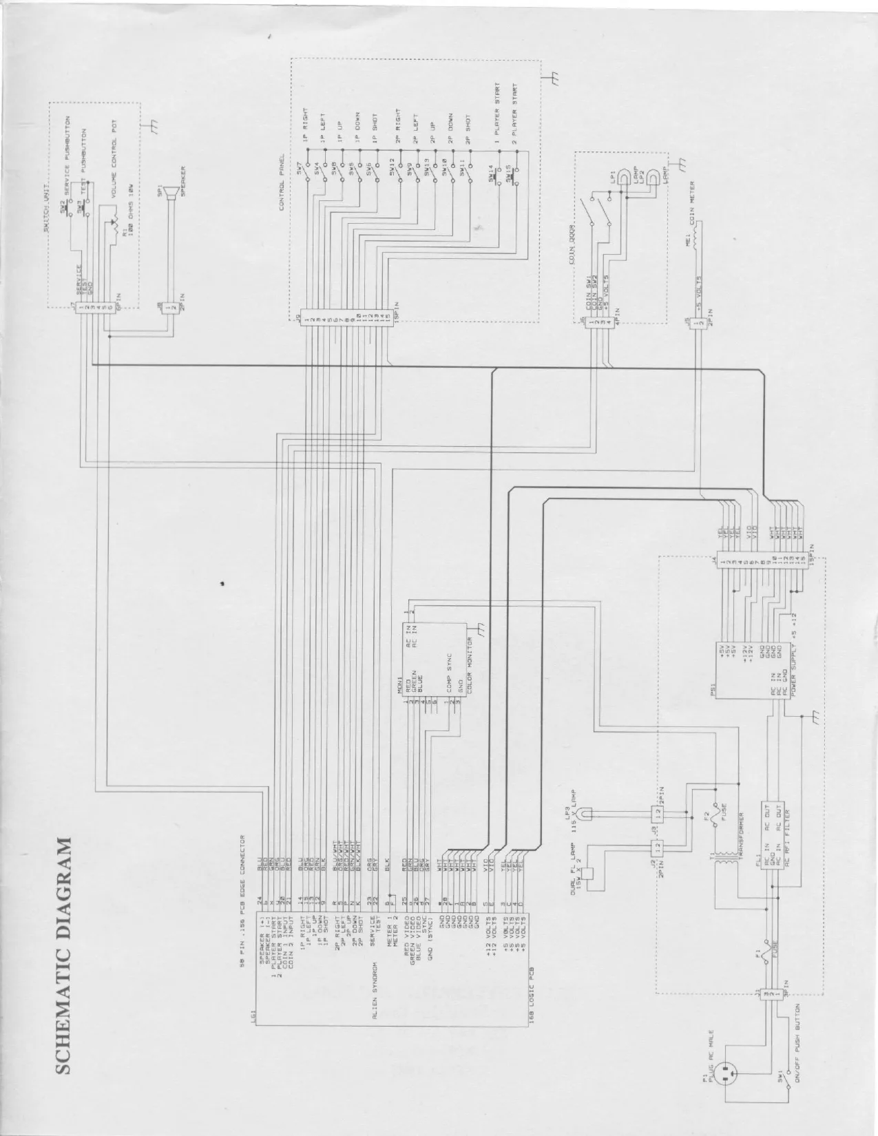
This page is a drawing, shown as the original scan.