Dragon Spirit TM-310 1st Printing
Dragon Spirit (new version (DS3)) (Namco, 1987) · Technical Manual · 52 pages · 68 sections · original scan
T™M-310 Ist printing
Operators Manual
with Illustrated Parts Lists
"Dragon Spirit is engineered and designed by Namco Ltd Manufactured by Atari Games. Trademark and © Namco 1987.
This page carries no recoverable text. It is a drawing or a photograph. See the original scan.
Operators Manual
with Illustrated Parts Lists
Games
© 1987 by Atari Games Corporation All rights reserved No part of this publication may be reproduced by any mechanical, photographic, or electronic process, or in the form of a phonographic recording, nor may it be stored ina retrieval system, transmitted, or otherwise copied for public or private use, without permission from the publisher. The game play, all graphic designs, this technical manual, its accompanying schematic diagrams, and the display manual are protected by the U.S. Copyright Act of 1976. This Act provides for increased penalties for violating federal copyright laws. Courts can impound infringing articles while legal action is pending. If infringers are convicted, courts can order destruction of the infringing articles. In addition, the Act provides for payment of statutory damages of up to $250,000 in certain cases. Infringers may also have to pay costs and attorneys’ fees and face an imprisonment of up to five years. Atari Games Corporation will aggressively enforce its copyrights against any infringers. We will use all legal means to immediately halt any manufacture, distribution, or operation of acopy of video games made by us. Anyone who purchases such copies risks forfeiting such a game.
Published by: Atari Games Corporation 675 Sycamore Drive P.O, Box 361110 Milpitas, California 95035
Printed in the U.S.A. OR Dragon Spirit
Dragon Spirit
Notice Regarding Non-ATARI® Parts
& WARNING A Use of non-ATARI parts or modifications of any ATARI game circuitry may adversely affect the safety of your game, and may cause injury to you and your players.
You may void the game warranty (printed on the inside back cover of this manual) if you do any of the following: © Substitute non-ATARI parts in the game. © Modify or alter any circuits in the game by using kits or parts not supplied by Atari Games Corporation.
NOTE
This equipment generates, uses, and can radiate radio frequency energy, and if not installed and used in accordance with the instruction manual, may cause interference to radio communications. It has been tested and found to comply with the limits for a Class A computing device pursuant to Subpart] of Part 15 of Federal Communications Commission (FCC) Rules, which are designed to provide reasonable protection against such interference when operated in a commercial environment. Operation of this equipment in a residential area or modification to this equipment is likely to cause interference, in which case the user, at his own expense, will be required to take whatever measures may be required to correct the interference. If you suspect interference from an ATARI® game at your location, check the following:
- All ground wires in the game are properly connected as shown in the game wiring diagram. © The power cord is properly plugged into a grounded three-wire outlet. © On games provided with an Electromagnetic Interference (EMI) ground plane, be sure the game printed-circuit boards (PCBs) are properly installed on the EMI Ground Plane. If you are still unable to solve the interference problem, please contact Customer Service at Atari Games Corporation. See the inside front cover of this manual for service in your area.
iii
Table of Contents
How to Use This Manual Inspecting the Game . . : Control and Switch Locations . peeks 7 : Setting the Coin and Game Option Settings .......... sees Game Play ... feias Dia Le fgets nese
Self-Test Self-Test Switches ...... Service Switch Types of Self-Tes' RAM/ROM Test Game Options Screen... ..... Switch Test . byt cen ee Sound Test Crosshatch Test Color Test
Maintenance Preventive Maintenance Preventive Maintenance Intervals. . Removing the Control Panel . Cleaning the Push-Button Leaf Switches . . Cleaning the Coin Mechanism Cleaning the Interior Components . . Joystick Control
Corrective Maintenance . Removing the Game PCB Removing the Video Display . Replacing the Video Display Removing the Speaker 3-6
Illustrated Parts Lists See List of Illustrations that follows. Dragon Spirit
Dragon Spirit
List of Illustrations
Figure 1-1
Figure 2-1 Figure 2-2 Figure 2-3 Figure 2-4 Figure 2-5
Figure 3-1 Figure 3-2 Figure 3-3
Figure 4-1 Figure 4-2 Figure 4-3 Figure 4-4 Figure 4-5 Figure 4-64 Figure 4-6B Figure 4-7
Table 1-1 Table 2-1 Table 2-2 Table 3-1 Control and Switch Locations «0.0.0.6... eee eee wees 12
Game Options Screen 23 Switch Test Screen .. . 2-4 Sound Test Screen 25 Crosshatch Test Screen . 2-5 Color Test Screen... . 2-6
Leaf Switch and Joystick Removal ............ 000000 c eee eee 3-3 Joystick Lubrication ...........0. 3-4 Control Panel, Video Display, and Speaker Removal . beeen 3-5
Cabinet-Mounted Assemblies ..... 2.000.600.0050 eee eee 4-2 Control Panel Assembly ........... 4-5 Joystick Assembly 4-6 Switching/Linear (SL) Power Supply Assembly . . sees 48 Coin Acceptors, Inc. Coin Door Assembly... . . a .. 412 Dragon Spirit CPU PCB Assembly 4-16 Dragon Spirit ROM PCB Assembly +19 Dragon Spirit End PCB Assembly 4-23
List of Tables
Game Specifications 1-3 RAM/ROM Error Messages . 23 Game Option Settings . beens 23 Recommended Preventive Maintenance Intervals - sey . 3-2
vi
Safety Summary
The following safety precautions apply to all game operators and service personnel. Specific warnings and cautions will be found throughout this manual where they apply.
A WARNING A
Properly Ground the Game. Players may receive an electrical shock if this game is not properly grounded! To avoid electrical shock, do not plug in the game until it has been inspected and properly grounded. This game should only be plugged into a grounded three-wire outlet. If you have only a 2-wire outlet, we recommend you hire a licensed electrician to install a grounded outlet. Players may receive an electrical shock if the control panel is not properly grounded! After servicing any parts on the control panel, check that the grounding wire is firmly secured to the inside of the control panel. Only then should you lock up the game. AC Power Connection. Before connecting the game to the AC power source, verify that the game’s power supply is properly configured for the line voltage in your location Disconnect Power During Repairs. To avoid electrical shock, disconnect the game from the AC power source before removing or repairing any part of the game. When removing or repairing the video display, extra precautions must be taken to avoid electical shock because high voltages may exist within the display circuitry and cathode-ray tube (CRT) even after power has been disconnected. Do not touch internal parts of the display with your hands or with metal objects! Always discharge the high voltage from the CRT before servicing this area of the game. To discharge the CRT: Attach one end of a large, well-insulated, 18-gauge jumper wire to ground. Momentarily touch the free end of the grounded jumper to the CRT anode by sliding it under the anode cap. Wait two minutes and discharge the anode again. Use Only ATARI Parts. To maintain the safety integrity of your ATARI game, do not use non- ATARI parts when repairing the game. Use of non-ATARI parts or other modifications to the game circuitry may adversely affect the safety of your game, and injure you or your players. Handle the CRT With Care. If you drop the CRT and it breaks, it may implode! Shattered glass can fly six feet or more from the implosion. Use the Proper Fuses. To avoid electrical shock, use replacement fuses which are specified in the parts list for this game. Replacement fuses must match those replaced in fuse type, voltage rating, and current rating. In addition, the fuse cover must be in place during game operation.
Chapter 1
Set-Up
How to Use This Manual
This manual is written for game operators and service technicians, and provides information for setting up, playing, testing, and maintaining your Dragon Spirit* game. The manual is divided into the following chapters: © Chapter 1 contains set-up and game play information. © Chapter 2 contains self-test procedures. © Chapter 3 contains preventive and corrective maintenance procedures. Chapter 4 contains illustrated parts lists. Schematic diagrams for the Dragon Spirit game circuitry are contained in the Schematic Package Supplement (SP-310) included with your game. This chapter includes information required to set up and play your Dragon Spirit game. Carefully read this information before applying power to the game.
A&A WARNING A
To avoid electrical shock, do not plug in the cabinet until it has been properly inspected and set up for the line voltage in your area. This cabinet should only be connected to a grounded three-wire outlet. If you have only a two-wire outlet, we recommend you hire a licensed electrician to install a grounded outlet. Players can receive an electrical shock if the game is not properly grounded. Do not touch internal parts of the display with your hands or with metal objects.
“Dragon Spirit is engineered and designed by Namco Ltd, Manufactured by Atari Games, Trademark and © Namco 1987.
set-up
Inspecting the Game
Please inspect your Dragon Spirit game carefully to ensure that the game is complete and delivered to you in good condition. Figure 4-1 shows the locations of the component parts of the game. Table 1-1 lists space, power, and environmental requirements.
1. Examine the exterior of the cabinet and the control panel for dents, chips, or broken parts. . Use a Phillips screwdriver to remove the screws holding the rear access panel to the cabinet. Unlock and remove the panel. Unlock and open both coin doors. Inspect the interior of the cabinet as follows: a. Ensure that all plug-in connectors (on the cabinet harnesses) are firmly plugged in. Do not force connectors together. The connectors are keyed so they only fit in the proper orientation. Dragon Spirit
om . Ensure that all plug-in integrated circuits on each PCB are firmly plugged into their sockets. c. Inspect the power cord for any cuts or dents in the insulation. d. Inspect the power supply. Make sure that the correct fuses are installed. Check that the harne: plugged in correctly and that the fuse-block cover is mounted in place. Check that the green ground wire is connected. e. Inspect other major subassemblies, such as the video display, printed-circuit boards (PCBs), control, and speaker. Make sure that they are mounted securely and that the green ground wires are connected. f. Make sure that the game power source and operating environment is within the limits specified in Table 1-1, Game Specifications.
Control and Switch Locations
The following control and switch descriptions are for the Dragon Spirit game. Refer to Figure 1-1 for the locations of the controls and switches.
Self-Test Switch
Service Switch (2 Connector Pins)
End PCB
Volume Control
Figure 1-1 Control and Switch Locations
Dragon Spirit
Table 1-1 Game Specifications
Characteristic Specification
Power Consumption 164 V-A, 118 W RMS maximum Temperature +5° to +38°C (+37° to + 100° F) Humidity Not to exceed 95% relative Line Voltage 102 to 132 VAC (U.S. games) Width 23'%, in. (61 cm) Depth 32 in. (81 cm) Height 70¥, in. (178 cm) Weight 265 Ibs. (120 kg)
Power On/Off Switch The power on/off switch is located at the bottom rear of the cabinet. (See Figure 4-1.)
Volume Control
The volume control is located in the lower right corner of the Game PCB. The PCB is attached to the lower right side of the cabinet. The volume control adjusts the level of sound produced by the game.
Coin Counter
The coin counter is located on the shelf behind the upper coin door. The coin counter records the number of coins deposited.
Self-Test Switch
The game can be put in the Self-Test Mode to check game operation by turning on one of the two existing self-test switches. One self-test switch is located on the End PCB, connected to the front of the Game PCB. Both PCBs are attached to the lower right side of the cabinet. Asecond self-test switch (switch 1) is located on the dualinline-package (DIP) switch in the upper right corner of the Game PCB. Turning on switch 1 also selects the Self- Test Mode. (With the PCB installed in the cabinet, slide the button down for on.) Refer to Chapter 2 for a complete description of self-test operation.
Service Switch
The service switch (a two-pin header connector) is located next to the self-test switch on the End PCB. The End PCB is connected to the front of the Game PCB, and both PCBs are attached to the lower right side of the cabinet. This switch has two functions, depending on whether the game is in the Self-Test Mode: Setup
- The switch is used as a coin switch when the game is not in the Self-Test Mode. Shorting the two connector pins together gives the game one credit.
- In the Self-Test Mode, the switch is used to advance to the next test screen by shorting the two connector pins together.
Setting the Coin and Game Option Settings
The Dragon Spirit coin and game options are set in the Self-Test Mode. Refer to Chapter 2 for the recommended. settings and the procedure for setting the options.
Game Play
This section of the manual describes the theme of the Dragon Spirit game and the game play features.
Introduction Turn back the hands of time and journey toa fantasy kingdom where mythical beasts and wild creatures roam the land. After a millennium of captivity, an ugly serpent demon named Zawell escapes imprisonment and kidnaps beautiful Alicia, princess to the Kingdom of Mitgult A young, but crafty soldier, Amul is selected to rescue the princess and destroy Zawell. In praying to the gods for strength and courage, he points his sword high toward the heavens. Suddenly he is transformed into an all-powerful blue dragon, bestowed with special powers.
Dragon Spirit is a one- or two-player game that is wellsuited for all locations. An eight-way joystick allows players to swoop and dodge through a constant onslaught of hungry, feasting predators. One button exercises a lethal air attack; the other a vicious ground assault. As a singleheaded dragon, he becomes weary in battle and cannot attack both air and ground simultaneously, Bombing and obtaining the contents of blue eggs provide the growth of additional heads and simultaneous air/ground attack. Red eggs reward the player with incremental firing power. At the conclusion of each of nine areas lies a mighty beast who guards the path to Zawell and the princess. Obtaining additional heads and firepower makes the
difference between a long, tiresome battle and a quick,
effortless one.
Set-Up
A level-select feature allows players the option of four starting points for maximum earning potential: Area 1; a one-headed dragon Area 2; a two-headed dragon Area 3: a two-headed dragon and 2 times the firepower Dragon Spirit
Area 4: a two-headed dragon and 3 times the firepower
In addition, players are encouraged to continue their games by granting a three-headed dragon. This is anew innovation to the already popular add-a-coin, buy-in feature.
Chapter 2
Self-Test
The Dragon Spirit* game tests itself and provides visual and audible indications of the condition of the game circuitry. Self-test information is displayed on the screen and through the sound system. No additional equipment is required.
We suggest that you perform a self-test when you first set
up the game, each time you collect the money, or when you suspect game failure. Coin and game options are selected in the Self-Test Mode.
Five self-test screens provide information pertaining to the game circuits. The tests are arranged in the sequence in which they occur after the self-test switch is turned on. When the self-test switch is turned on, and then the game power is turned on, the game enters the full Self-Test Mode. During this full self-test, a complete RAM/ROM test is performed before displaying the Game Options screen. If the self-test switch is turned on when the game is in the Attract Mode, the game enters a shorter Self-Test Mode. Turning the self-test switch off at any time during the Self- Test Mode causes the game to return to the Attract Mode.
*Dragon Spirit is engineered and designed by Namco Ltd. Manufactured by Atari Games, Trademark and © Namco 1987.
Self-Test
Self-Test Switches
The game can be put in the Self-Test Mode to check game operation by turning on one of two existing self-test switches. One self-test switch is located on the End PCB, connected to the front of the Game PCB. Both PCBs are attached to the lower right side of the cabinet. (See Figure 1-1.) Asecond self-test switch (switch 1) is located on the dualinline-package (DIP) switch in the upper right corner of the Game PCB. Turning on switch 1 also selects the Self- Test Mode. (With the PCB installed in the cabinet, slide the button down for o77.)
Service Switch
The service switch (a two-pin header connector) is located next to the self-test switch on the End PCB. The End PCB is connected to the front of the Game PCB, and both PCBs are attached to the lower right side of the cabinet. This switch has two functions, depending on whether the game is in the Self-Test Mode:
- The switch is used as a coin switch when the game is not in the Self-Test Mode. Shorting the two connector pins together gives the game one credit.
- In the Self-Test Mode, the switch is used to advance to the next test screen by shorting the two connector pins together.
Types of Self-Tests
The Dragon Spirit self-test consists of the following screens: Game Options, Switch Test, Sound Test, Crosshatch Test, and Color Test.
2-2 Dragon Spirit
RAM/ROM Test When the self-test switch is turned on, and then the game power is turned on, the game enters the full Self-Test Mode. During this mode a complete RAM/ROM testis performed. The RAM Test indicates the condition of the game RAM and the custom integrated circuits (ICs). The ROM Test indicates the condition of the game’s ROM circuitry. If these tests pass, no screen message is displayed, and the game proceeds directly to the Game Options Screen. If the RAM or any of the custom ICs fail, the message RAM x ERROR or I/O ERROR 64 is displayed. If any of the ROMs fail, the screen displays the message ROM x ERROR (see Table 2-1 for all RAM/ROM error messages).
Game Options Screen
The Game Options screen is shown in Figure 2-1. This screen indicates the current settings of the coin and game options, and is also used to change these settings. Table 2-2 lists the available options and the default (recommended) settings.
Coin and Credit Options
The current coin and credit option settings are displayed on the screen as:
COINI 1 COIN 1 CREDIT
COIN2 1 COIN 1 CREDIT These are the default (recommended) settings for coin mechanisms 1 (left) and 2 (right). The available coin and credit options are as follows:
Coin 1: 1 to 9 Coin(s) for 1 to 9 Credit(s) Coin 2: 1 to 9 Coin(s) for 1 to 9 Credit(s) The coin and credit options can be changed by moving the joystick left/right.
Attract Mode Music Setting The Attract Mode Music setting indicates that music is selected when the game is in the attract mode. This setting is displayed on the screen as: ATTRACT SOUND The default (recommended) setting has the sound on. The sound can be turned off by moving the joystick left/ right.
Dragon Spirit
Table 2-1 RAM/ROM Error Messages
ROM PCB is the larger circuit board. CPU PCB is the smaller circuit board.
Error Message Possible Bad Integrated Circuit
ROMO ERROR — ROM at location H10 on the ROM PCB ROM 1 ERROR = ROMat location K10 on the ROM PCB ROM 2 ERROR — ROMat location L10 on the ROM PCB ROM 3 ERROR — ROM at location M10 on the ROM PCB. ROM4 ERROR — ROM at location N10 on the ROM PCB ROM 5 ERROR = ROM at location P10 on the ROM PCB ROMGERROR — ROM at location $10 on the ROM PCB ROM7ERROR — ROM at location T10 on the ROM PCB
RAM 1 ERROR* RAM at location B2, D2, or E2 on the CPU PCB RAM 2 ERROR RAM at location D6 or E6 on the CPU PCB RAM 3 ERROR — RAM at location $5 on the CPU PCB RAM 4 ERROR RAM at location H1 on the CPU PCB RAMS ERROR RAM at location LS on the CPU PCB RAM 6 ERROR* RAM at location B2, D2, or E2 on the CPU PCB RAM 7 ERROR RAM at location D6, or E6 on the CPU PCB
1/O ERROR 64** RAM at location H1 on the CPU PCB, or the I/O Processor at location M4 on the ROM PCB
*Either of these error messages may be accompanied by a four-digit number. Look at the first of the four lines and ignore the bottom three lines. Also ignore the fact that the entire screen may be upside down. This four-digit number may indicate one specific integrated circuit is bad, as follows: If the number is between 0002 and 0802, this indicates location B2. If ABCD is between 0804 and 1002, this indicates location D2. If ABCD is between 1004 and 1802, this indicates location E2.
*"If this error message is accompanied by a four-digit number, look
If ABCD is between 1004 and 1802, this indicates location E2 at its left two digits. If those digits are 0.2, this indicates the RAM at
location H1 is bad. If those digits are not 02, this indicates the I/O Processor at location M4 is bad.
Cabinet Type Setting
The Cabinet Type setting indicates that the cabinet is the normal, upright type with one set of player controls. This setting is displayed on the screen as:
TYPE Cc
Do not change this default (recommended) setting.
Video Display Orientation Setting
The Video Display Orientation setting is displayed on the screen as:
FLIP ON
Do not change this default (recommended) setting. Self-Test
Figure 2-1 Game Options Screen
Table 2-2 Game Option Settings
Option Name Available Settings
Coins to start 6, 7, 8, 9 Coin(s) for (Coin Mech 1 or left , 8, 9 Credit(s) one)
Coins to start 1 <4, 2, 3, 4,5, 6, 7, 8, 9 Coin(s) for (Coin Mech 2 or right 1 ~4, 2,3, 4, 5, 6, 7, 8, 9 Credit(s) one)
Music in attractmode Sound 4 Off
Cabinet type A B ca
Video display orienta. On < tion (“flip”) Off Starting lives (dragons) 2 per game 3
Game difficulty ‘A (Medium) (“rank”) B (Hard) C(Ea Game continuation with add-a-coin
First extra life 40,000 points 80,000 points <4 120,000 points 150,000 points 200,000 points <4 250,000 points Second extra life
<< Manufacturer's recommended settings
Self-Test
Starting Lives Setting
The Starting Lives setting indicates the number of lives granted when game play begins, and is displayed on the screen as:
DRAGON 3 3 lives is the default (recommended) setting. The setting can be changed to 2, 4, or 5 lives by moving the joystick left/right.
Game Difficulty Setting
The Game Difficulty setting indicates the difficulty level of the game, and is displayed on the screen as: RANK cos C (easy) is the default (recommended) setting. The setting can be changed to A (medium) or B (hard) by moving the joystick left/right.
Game Continuation Setting
The Game Continuation setting indicates game continuation with the add-a-coin feature. This setting is displayed on the screen as: CONTINUE ON On is the default (recommended) setting. The setting can be changed to Off by moving the joystick left/right.
Extra Life Settings
The Extra Life settings indicate when first and second extra lives are granted, and are displayed on the screen as: 1ST EXTEND 80,000 80,000 points is the default (recommended) setting for the first extra life. The setting can be changed to 40,000 or 120,000 points by moving the joystick left/right. 2ND EXTEND — 200,000 200,000 is the default (recommended) setting for the second extra life. The setting can be changed to 150,000 or 250,000 points by moving the joystick left/right.
Switch Test
The Switch Test screen is shown in Figure 2-2. This test indicates the current DIP switch settings, and tests the self-test switch, start switches, coin mechanisms, player control, and buttons.
Figure 2-2 Switch Test Screen
DIP Switch Settings
The Dragon Spirit game has one DIP option switch at location 3A on the Game PCB. (See Figure 1-1.) The DIP Switch settings indicate the current settings of the DIP Switch, and are displayed on the screen as DIPSW 12345678 The row of numbers refers to switches 1 through 8 on Switch A. When the switch number is displayed in red, the switch is on. When the number is white, the switch is off.
To change the settings, use a pen or a sharp-pointed instrument to slide the appropriate small buttons to different settings. With the Game PCB installed in the cabinet, slide the button down for on and up for off.
Self-Test Switch The Self-Test Switch setting indicates the condition of the self-test switch and is displayed on the screen TESTSW (This switch is always on in the Self-Test Mode.)
Start Switch The Start Switch setting indicates the condition of the two black-cap LED Start switches, and is displayed on the screen as:
STARTI START2
Dragon Spirit
Coin Mechanisms
The Coin Mechanisms setting indicates the condition of the left and right coin mechanisms and is displayed on the screen as:
COINT COIN2
COIN1 refers to the left mechanism and CO/N2 the right mechanism.
Joystick
The Joystick setting indicates the condition of the joystick
and is displayed on the screen as: uP LEFT RIGHT DOWN (STICK1) Moving the joystick up/down or left/right displays that position in red. $7/CK2 or joystick 2 is not used in Dragon Spirit.
Fire and Bomb Buttons
The Fire and Bomb button setting indicates the condition of the Fire and Bomb buttons and is displayed on the screen as:
Bl B2 B3 (BUTTONS) B1 is the red Fire button and B2 is the yellow Bomb button. B3 is not used in Dragon Spirit.
Sound Test
The Sound Test screen is shown in Figure 2-3. This screen indicates the condition of the sound-effects circuitry (when sound is selected in the Attract Mode setting). This test is displayed on the screen as:
Figure 2-3 Sound Test Screen Self-Test
VOICE NUMBER 000
PSG NUMBER 00
FM NUMBER 00
AUDIO
3D TEST
Voice number indicates the one voice phrase in the game. PSG Number indicates sound effect, and FM number indicates music. Audio tests the channels. (In Dragon Spirit one speaker is used for both channels.) The 3D Test is not used.
Moving the joystick up/down or left/right selects the different item number. Pressing the Fire button starts the selected sound.
Crosshatch Test
The Crosshatch screen is shown in Figure 2-4. This screen indicates the condition of the video display size and linearity, and is used to adjust both. The grid pattern should be white. Check this pattern for the following characteristics: ¢ The four corners of the frame around the grid pattern should touch all four corners of the screen.
- The grid lines should exhibit no pincushioning or barreling. Refer to the display manual included with your game for more detailed adjustment procedures or to determine possible cause of failure.
Color Test
The Color Test screen is shown in Figure 2-5, This screen indicates the condition of the video display color circuits, and is used to adjust the color and brightness.
Figure 2-4 Crosshatch Test Screen
Self-Test
Figure 2-5 Color Test Screen Dragon Spirit
There should be four vertical bars of white, blue, green, and red. The bars should be brightest at the top of the screen, and darkest (black) at the bottom. The middle of the bars are dim. If the display characteristics are not correct, refer to the display manual included with your game for the colorgun adjustment procedure, or to determine the possible cause of failure.
Chapter 3
Maintenance
This chapter includes preventive and corrective maintenance procedures for the Dragon Spirit game components that are subject to the most use. To assure maximum. trouble-free operation from this game, we recommend that preventive maintenance be performed as described in this chapter. Removal and replacement procedures are provided for components that might require corrective maintenance. Chapter 4, Illustrated Parts Lists, can also be used to locate the parts of this game that are mentioned, but not illustrated, in the maintenance procedures.
Maintenance Dragon Spirit
Preventive Maintenance
Preventive maintenance includes cleaning, lubricating, and tightening hardware. How often preventive maintenance is performed depends upon the game environment and frequency of play. However, for those components listed in Table 3-1 Preventive-Maintenance Intervals, we recommend that preventive maintenance be performed at the intervals specified.
Preventive-Maintenance Intervals
The preventive-maintenance intervals specified in Table 3-1 are the recommended minimum requirements for the components listed.
A WARNING A
To avoid possible electrical shock, turn off the game before performing any maintenance procedures.
Removing the Control Panel
Perform the following procedure to remove/replace the control panel. (See Figure 3-3.)
- Unlock and open the upper coin door and the front access panel.
- Carefully reach up through the upper coin door opening and release the two spring draw latches located under the control panel on each side of the cabinet.
- Grasp the control panel on the top edge (next to the display shield) and gently tilt the panel up slightly. Remove the panel from the front edge of the cabinet. Stand the control panel on its back edge by placing it in the wood slots located under the control panel on each side of the cabinet. The panel is now in position for servicing the leaf switches or the joystick control.
- If you need to remove the control panel, disconnect the control harness connector from the Game PCB.
- Carefully lift the control panel from the cabinet.
- Replace the control panel in the reverse order of removal.
Table 3-1 Recommended Preventive- Maintenance Intervals
Joystick Control Lubricate and tighten hardware at least every three months. Inspect whenever you collect coins. Coin Mechanism Clean at least every three months.
3-2
Cleaning the Push-Button Leaf
Switches
Perform the following procedure to clean the push-button leaf switch contacts and tighten the securing hardware, (See Figure 3-1.)
- Follow the procedure described in steps 1-3 above for removing the control panel.
- Use electrical contact cleaner to clean the contacts. Do not burnish them. When the push button is pressed, the wiping action of the cross-bar contacts provides a self-cleaning feature.
- Using a '%,-inch open-end wrench, tighten the stamped nut securing the pushbutton leaf switch to the control panel
Cleaning the Coin Mechanism Use a soft-bristled brush to remove loose dust or foreign material from the coin mechanism. A toothbrush can be used to remove any stubborn build-up of residue in the coin path. After cleaning the coin mechanism, blow out all of the dust with compressed air.
Cleaning the Interior Components Perform the following procedure to clean the components inside the cabinet.
‘Turn off the game power, but do not unplug the power cord before cleaning inside the cabinet. The power cord provides a ground path for stray static voltages that might be present on the cleaning tools.
- Unlock and remove the front access panel.
- Use a vacuum cleaner with a soft long-bristled brush attachment or a soft-bristled paint brush to remove loose dirt and dust accumulated on the inside of the cabinet. Be sure to clean the electrical components thoroughly (power supplies, PCB assemblies, display, etc.).
Dragon Spirit Maintenance
Control Panel Decal
1”-Long Carriage Bolt
Control Panel Harness Assy
Cross-Bar Leaf Switch with = a Button Holder —— a
Push-Button Switch
Leaf Switch with Button Holder Yellow Button Assy
Lock Nut
8-Position Joystick Assy
Stamped Nut
Figure 3-1 Leaf Switch and Joystick Removal
Joystick Control
Preventive maintenance on the joystick control consists of inspecting the pivot and actuator balls for excessive wear or dirt, lubricating the pivot ball, adjusting the leaf switches and, if necessary, replacing or tightening the securing hardware.
Lubricating the Joystick Control
Perform the following procedure to lubricate and tighten the joystick control. (See Figure 3-2.)
- Remove the control panel as previously described.
- Apply a light film of Lithium grease (Atari part no. 107027-001) to the lubrication points shown in Figure 3-2.
- Using a %-inch wrench, tighten the four nuts holding the joystick to the control panel.
- Using a %-inch wrench (or an appropriate tool), tighten the four screws holding the positioning plate to the lower housing.
Corrective Maintenance
Corrective maintenance consists of removing, disassembling, reassembling, and replacing the push-button leaf switches, joystick control, game printed-circuit board (PCB), video display, and speaker. The procedures for removing and replacing the Game PCB, video display, and the speaker follow.
3-3
Maintenance
#8-16 Screw
Lubrication Points a ~Sai?
Cushion Ring
#4-20 Screw
Actuator
Lock Nut
8-Position Plate
Figure 3-2 Joystick Lubrication
Removing the Game PCB
Perform the following procedure to remove/replace the Game PCB.
- Turn the cabinet power off. Upper Housing Assembly Dragon Spirit
Nv Unlock and remove the front access panel from the cabinet.
- Disconnect the harness connectors from the Game PCB.
4, Use a Phillips screwdriver to remove the six screws and washers holding the Game PCB and End PCB to the cabinet.
- Grasp the front edge of the Game PCB and gently slide it forward out of the slotted guide.
- Disconnect the End PCB from the Game PCB. . Replace the Game PCB in the reverse order of removal. x
Removing the Video Display
Perform the following procedure to remove/replace the video display. (See Figure 3-3.)
- Turn the game power off and wait two minutes. Unplug the power cord.
- Remove the control panel as described under Preventive Maintenance.
- Remove the video display shield
- Carefully remove the bezel from the foam tape holding it in place.
- Use a Phillips screwdriver to remove the four screws holding the rear access panel to the cabinet
A WARNING A
High Voltage The video display contains lethal high voltages. To avoid injury, do not attempt to service this display until you observe all precautions necessary for working on high-voltage equipment. X-Radiation The video display has been designed to minimize X-radiation. However, to avoid possible exposure to soft X-radiation, never modify the high-voltage circuitry. Implosion Hazard The cathode-ray tube may implode if struck or dropped. Shattered glass may cause injury within a 6foot radius. Use care when handling the display.
- Discharge the high voltage from the cathode-ray tube (CRT) before proceeding. The display assembly contains a circuit for discharging the high voltage to ground when power is removed. However, to make certain, always discharge the display as follows.
Dragon Spirit Maintenance
Speaker Grille
Video Display Shield
Grille Mounting Screws (6 Places) Split-Lock Washer
Figure 3-3 Control Panel, Video Display, and Speaker Removal
a. Attach one end ofa large, well-insulated, 18-gauge 9. Carefully slide the display out through the front of jumper wire to ground. the cabinet. b. Momentarily touch the free-end of the grounded 10. Replace the video display as described in the followjumper to the CRT anode by sliding it under the ing procedure. anode cap. c. Wait two minutes and repeat part b.
- From the back of the cabinet, unplug the display har- NOTE ness connectors from the display. ‘Whenever the cathode-ray tube and yoke are replaced as a single unit, readjust the brightness, size, and cen- A WARNING A Pauly and convergence aloo Sectecng to the dplay To avoid dropping the video display, use extreme care manual instructions, but adjust both only if required. when removing the display from the cabinet. We recommend that no one weighing less than 150 pounds should attempt to remove the video display. In addition, we recommend that you wear gloves to protect
your hands from the sheet-metal edges. Replacing the Video Display
Perform the following procedure to replace the video dis-
- Use a % inch wrench to remove the four nuts and play in the cabinet. (See Figure 3-3.) washers holding the video display to the cabinet 1. Gently lift the video display through the front of the cabinet.
Maintenance
- Position the display so that the four slots in the chassis are aligned with the corresponding mounting holes in the cabinet shelf.
- Tighten the four mounting nuts and washers using a 4-inch wrench.
- Connect the display harness to the display PCB. . Replace the bezel.
- Replace the video display shield. wn
Removing the Speaker
Perform the following procedure to remove/replace the speaker. (See Figure 3-3.)
- Usea Y-inch square drive bit to remove the five screws holding the speaker grille to the cabinet. Remove the grille.
3-6 Dragon Spirit
. Use a Phillips screwdriver to remove the four screws holding the speaker to the cabinet: Remove the speaker just far enough to disconnect the two speaker wires. 4, With the tabs pointed outward, replace the speaker in the reverse order of removal.
Chapter 4
Illustrated Parts Lists
This chapter provides information you need to order parts for your game. Common hardware (screws, nuts, washers, etc.) has been deleted from most of the parts lists. The PCB parts lists are arranged in alphabetical order by component. Each component subsection is arranged alphanumerically by reference designator. Other parts lists are arranged alphanumerically by Atari part number. In these parts lists, all A-prefix numbers come first. Following these are numbers in sequence evaluated up to the hyphen, namely 00- through 99-, then 000598- through approximately 201000-. When ordering parts, please give the part number, part name, number of this manual, and serial number of your game. This will help us fill your order rapidly and correctly. We hope the results will be less downtime and more profit from your game. Atari Customer Service numbers are listed on the inside front cover of this manual.
Illustrated Parts Lists Dragon Spirit
78-6900402 Ya" Jp" Foam Tay 044827-01 wh pe Attraction Shieid 044850-01 o4sz7602 Osaanwex Speaker Cover Grille 044830-01 Machined Retainer attraction Film with Graphics Display Shield 99-11006 178056-002 Retainer Clip Yel x Je" Foam Tape
NE 148007-104 ” Speaker
; vad
\ 171086-001
- * Lamp Fixture
044829-01 170003-001 Display Bezel with Graphics thi isplay Bezel with Graphi 439031-002 Fluorescent Lamp Sanyo Display 044845-01 Rear Access Panel
038091-01 Molded Coin Box
Control Panel Assy See Figure 4-2
8-Position Joystick Assy See Figure 4-3 Sh eS | 4 5 ZA fF
A044823-01 Cabinet Assy
A044072-01 Coin Counter Assy 044853-01 oe Front Access Panel Coin Door Assy 78-3201 See Figure 4-5 Adjustable Glide
A044861-01 Main Harness Assy
Figure 4-1 Cabinet-Mounted Assemblies A044820-01 B
Dragon Spirit Illustrated Parts Lists
Items Not Shown:
034536-02 Vibration Damper 178013-001 Spring Draw Latch NOTE To comply with emission requirements, the Mann areas Federal Communications Commission re- 037332-01 quires that the ground strap be secured to A044865-01 Louvered Grille both the Game PCB and End PCB Assem- +5V Harness Assy blies. Do not operate this game without A044862-01 properly installing the ground strap. AC Harness Assy A044866-02 Ground Strap Assy A044864-01 Video Harness Assy
A044866-01 Ground Strap Assy 044831-01 Ground Plate
End PCB Assy See Figure 4-7
Power Supply Assy See Figure 4-4
Game PCB Assy See Figure 4.6
042914-01 Ventilation Grille 178093-001 Fan Blade Guard
‘A043910-01 On/Off Switch Assy with Harness
Figure 4-1 Cabinet-Mounted Assemblies, Continued
Illustrated Parts Lists Dragon Spirit
Cabinet-Mounted Assemblies Parts List
Part No. Description
A043910-01 4-Inch-Long On/Off Switch Assembly with Harness A044072-01 12 VDC Non-Resettable Coin Counter Assembly A044823-01 Cabinet Assembly A044861-01 Main Harness Assembly
A044862-01 AC Harness Assembly A044864-01 Video Harness Assembly A044865-01 +5 V Harness Assembly A044866-01 Ground Strap Assembly A044866-02 Ground Strap Assembly 78-3201 Adjustable Glide 78-6900402 Y-Inch-Wide x /-Inch-Thick Foam Tape (24 inches required; used on control panel edge resting directly on display shield) 99-11006 Fluorescent Lamp Retainer Clip
034536-02 0.50-Inch-Thick Foam Vibration Damper 037332-01 Louvered Grille 038091-01 Molded Coin Box 042914-01 Ventilation Grille
043276-02 Machined Retainer 044808-01 Attraction Film with Graphics 044827-01 Attraction Shield 044829-01 Video Display Bezel with Graphics
044830-01 Video Display Shield 044831-01 Ground Plate 044845-01 Rear Access Panel 044850-01 Speaker Cover Grille
044853-01 Front Access Panel 139021-002 Sanyo Model 20-Z2AD 19-Inch Color Raster Video Display 148007-104 4% -Inch Round, 82, 10W, Shielded Speaker 170003-001 18-Inch-Long 50 W Fluorescent Lamp 171086-001 18-Inch-Long 118 V 60 Hz Fluorescent Lamp Fixture 178013-001 Spring Draw Latch 178056-002 Ye-Inch-Wide x J/c-lnch-Thick Foam Tape (4 inches required; used on comers on underside of display bezel) 178093-001 Fan Blade Guard The following items are the technical information supplements for this game: TM-310 Dragon Spirit Operators Manual SP-310 Dragon Spirit Schematic Package ST310 Dragon Spirit Self-Test Label TM311 sanyo 19” Color Raster Video Display Service Manual
4-4
Dragon Spirit Illustrated Parts Lists
044826-01 Control Panel Decal
178030-004 75-5116B Red Button Assy 178030-007 1-Inch-Long Carriage-Bott Yellow Button Ass\ 9 y
044825-01 Control Panel ‘ADEIES 69 Harness Assy
160013-002 Cross-Bar Leaf Switch with Button Holder
036895-01 Bezel
177010-240 Lock Nut
62-041 Push-Button Switch vemeuron oe 8-Position Joystick Assy 160013-001 See Figure 4-3 Leaf Switch with Button Holder 75-9910NO ‘Stamped Nut
Figure 4-2 Control Panel Assembly A044824-01 A
Control Panel Assembly Parts List
Part No. Description
A040933-03 8-Position Snap-Action Switch Joystick Assembly A044863-01 Control Panel Harness Assembly 62.041 Black Cap (No LED) SPDT Push-Button Switch 75-5116B #10-24 x 1.00-Inch-Long Black Carriage Bolt
75-9910NO #11-%-Inch Stamped Nut 036895-01 Black Molded Bezel 044825-01 Control Panel 044826-01 Control Panel Decal
160013-001 Leaf Switch with Button Holder 160013-002 Cross-Bar Leaf Switch with Button Holder 177010-240 #10-24 Lock Nut 178030-004 Red Button Assembly 178030-007 Yellow Button Assembly
Illustrated Parts Lists Dragon Spirit
72-1648F #6-32 Screw
A040932-01 Lubrication Points Upper Housing Assy iL Mir
041287-01 Lower Housing
160038-001 Snap-Action Switch ;
176030-110 #4-20 Screw
039714-01 Actuator
039717-03 8-Position Plate
Figure 4-3 8-Position Joystick Assembly A040933-03 D
4-6
Dragon Spirit Mlustrated Parts Lists
8-Position Joystick Assembly Parts List
Part No. Description
72-1648F #6-32 x 3-Inch-Long Phillips Pan-Head Screw A040932-01 Upper Housing Assembly 039714-01 Actuator 039717-03 8-Position Positioner Plate 041287-01 Lower Housing
044390-01 Cushion Ring 160038-001 Snap-Action Switch (Acceptable substitutes are part numbers 160041-001 SPST Switch and 160044-001 SPDT Switch) 176030-110 #4-20 x .62-Inch-Long Self-Tapping Hex Washer-Head Screw 177010-436 #6-32 Polymer Hex Nut
4-7
Illustrated Parts Lists
4 WARNING A The switching power supply has high vottages on it when power is turned on. Therefore, be sure you do not touch this power supply unless you have turned off the power Dragon Spirit
The Astec 5V/12V power supply is not assembled exactly as illustrated below. The Astec power supply, all of its accompanying hardware, and the 50 @ resistor are turned 180° from the view shown. In other words, the 5V Harness Assy. exits from the Astec power supply at the back of the power supply chassis.
149007-001 Astec 5V/12V Switching Power Supply to the game.
A044401-02 5V Power Supply Harness Assy
179231-002 Terminal Biock
A043367-01 Jumper Assy
‘A042384-01 Line Filter Assy
72-HA4608S, Screw
043908-01 Fuse Label
ZA) 82013002 Fuse
179225-2201 034544-01 Fuse Block Fuse Block Cover A044089-01 5V Harness Assy 72:HA4616S Screw
= a 175004-706 Yaa :
Washer Ne
178181-6808 Standoff
116024-500 ‘50 0 Resistor
aa 142045-001 Transformer
037640-01
043396-01 Power Supply Chassis Base
72-HA4806S,
Figure 4-4 Switching/Linear (SL) Power Supply Assembly A044339-02 B
Dragon Spirit
Switching/Linear (SL) Power Supply Assembly Parts List Illustrated Parts Lists
Part No. Description
A042384-01 A043367-01 A044089-01 A044337-01
A044401-02 46-2013002 72-HA4608S 72-HA4616S
72-HA4806S 85-22F206 034544-01 037640-01
043396-01 043908-01 116024-500 149007-001
175004-706 Line Filter Assembly Jumper Assembly 5 V Harness Assembly Transformer Termination Assembly
5 V Power Supply Harness Assembly 250 V Slow-Blow 3 A Fuse #6-32 x ¥2-Inch Cross-Recessed Pan-Head Thread-Forming Screw #6-32 x 1-Inch Cross-Recessed Pan-Head Thread-Forming Screw
32 x 4-Inch Cross-Recessed Pan-Head Thread-Forming Screw #2-56 x ¥-Inch Cross-Recessed Pan-Head thread-Forming Screw Fuse Block Cover Power Supply Warning Label
Power Supply Chassis Base Power Supply Fuse Label 50 Q, 5 W, Chassis-Mount Resistor Astec 5 V/12 V Switching Power Supply
#6 Fiber Washer 178181-6808 -171-Inch ID, ¥-Inch OD, Aluminum Standoff 179225-2201 1-Position Fuse Block 17923 1-002 2-Position Terminal Block
Astec 5-Volt Power Supply Sub-Assembly Model SA40-1304 Parts List
| Designator | Description | Part No. |
Capacitors
| C1, C2 | Capacitor, Met Poly, .1 wF, + 20%, 250 VAC | 99-209076 |
| C3, C4 | Capacitor, Poly, 2200 pF, + 20%, 250 VAC | 99-209077 |
| C5 | Capacitor, Met Poly, 2200 pF, + 20%, 250 V | 99-209080 |
| C8 | Capacitor, Electrolytic, 220 uF, + 100 -+ 10%, 10 V | 99-209072 |
| co | Capacitor, Ceramic, 1000 pF, + 20%, 3 KV, Z5P | 99-209068 |
| C10 | Capacitor, Met Poly, .022 pF, + 20%, 250 VAC | 99-209079 |
| cu | Capacitor, Poly, .22 wE, + 10%, 100 V | 99-209014 |
| ci2 | Capacitor, Electrolytic, 2200 uF, + 20%, 16 V, Sxa | 99-209073 |
| C13 | Capacitor, Poly, .01 uF, +5%, 50 V | 99-209075, |
| cl4 | Capacitor, Electrolytic, 100 pF, + 20%, 25 V, Sxa | 99-209006 |
| cls | Capacitor, Electrolytic, 1000 uF, + 20%, 16 V, Sxa | 99-209008 |
| C16 | Capacitor, Poly, .022 pF, + 20%, 50 V | 99-209078 |
| CI? | Capacitor, Electrolytic, 1000 pF, + 20%, 10 V, Sm | 99-209071 |
| C18 | Capacitor, Ceramic, 330 pF, + 20%, 100 V, SI | 99-209069 |
| C19 | Capacitor, Electrolytic, 470 uF, + 20%, 16 V, Sm | 99-209074 |
| 20 | Capacitor, Electrolytic, 100 pF, + 20%, 16 V, Sm | 99-209070 |
| C21 | Capacitor, Poly, .22 wE, + 10%, 100 V | 99-209014 |
| C23 | Capacitor, Ceramic, .01 uF, + 80- + 20%, 100 V, Z5U | 99-209003 |
Diodes
| D1 | Diode, RGP10A. | 99-209083, |
| D2 | Diode, RGP10J | 99-209033 |
Ilustrated Parts Lists Dragon Spirit
Astec 5-Volt Power Supply Sub-Assembly
Model SA40-1304 Parts List, Continued
| Designator | Description | Part No. |
| D3 | Diode, GP10A | 99-209084 |
| D4, DS | Diode, RGP10J | 99-209033, |
| D6, D7 | Diode, 1N4606 | 99-209030 |
| Ds | Assembly, Regulator/SCR/Diode/Heat Sink | 99-209105 |
| D8 | Diode, 12CTQ035 | 99-209107 |
| D9 | Diode, RGP10B | 99-209034 |
| D10 | Assembly, Diode/Heat Sink | 99-209103 |
| DiI | Diode, 1N4606 | 99-209030 |
| D12, D13 | Diode, 1N4001 | 99-209035 |
| DBL | Diode, Bridge, KBP08. | 99-209085 |
Inductors
| 13, | Inductor, 2.2 pH | 99-209029, |
| L4 | Inductor, 1.5 mH | 99-209028, |
| Ls | Assembly, Inductor Coil | 99-209059 |
| Lo | Inductor, 4.4 pH | 99-209102 |
Transistors
| Ql | Transistor, NPN, 25C2120 | 99-209082 |
| Q2 | Assembly, Transistor/Heat Sink | 99-209104 |
| Q@ | Transistor, PNP, 2SB561 | 99-209022 |
Resistors
| RI | Resistor, Carbon Film, 470K Q, +5%, % W | 99-209089 |
| R2 | Resistor, Wirewound, 33 2, +5%,3 W | 99-209097, |
| R3, R4 | Resistor, Metal Oxide Film, 100K 2, +5%,1W | 99-209054 |
| RS | Resistor, Carbon Film, 1KQ, +5%, 4 W | 99-209086 |
| RO | Resistor, Metal Oxide Film, 1200, +5%,2W | 99-209095 |
| R7 | Resistor, Metal Film, 19, +5%, 1 W | 99-209025 |
| R8 | Resistor, Carbon Film, 270, 45%,’ W | 99-209040 |
| RO | Resistor, Carbon Film, 682, +5%, 4 W | 99-209090 |
| R10 | Resistor, Carbon Film, 102, +5%, 4 W | 99-209037 |
| R11 | Resistor, Carbon Film, 150, +5%, A W | 99-209087 |
| R12 | Resistor, Metal Film, .75 0, +5%, 1 W | 99-209091 |
| R13 | Resistor, Carbon Film, 5.60, +5%, 4 W | 99-209046 |
| R14 | Resistor, Carbon Film, 47 2, +5%, 4 W | 99-209043 |
| R15, R16 | Resistor, Carbon Film, 2709, +5%, % W | 99-209041 |
| R17 | Resistor, Carbon Film, 8.2, +5%, 4 W | 99-209049 |
| R18 | Resistor, Carbon Film, 3302, +5%, 4 W | 99-209042 |
| R19 | Resistor, Carbon Film, 56, +5%, 4 W | 99-209045 |
| R20 | Resistor, Carbon Film, 682, +5%, 4 W | 99-209090, |
| R21 | Resistor, Carbon Film, 3302, +5%, % W | 99-209042 |
| R22 | Resistor, Carbon Film, 4702, +5%, 4 W | 99-209044 |
| R23, | Resistor, Metal Film, 8.2KQ, +1%, 4 W | 99-209094 |
| R24 | Resistor, Metal Film, 2.7K Q, +1%, %4 W | 99-209093 |
| R25 | Resistor, Metal Film, 18K Q, +1%, 4 W | 99-209092 |
| R27 | Resistor, Carbon Film, 222, +5%, 4 W | 99-209088, |
| R28 | Resistor, Carbon Film, 102, +5%, 4 W | 99-209037 |
| R29 | Resistor, Metal Oxide Film, 1200, +5%,2W | 99-209095 |
Dragon Spirit Illustrated Parts Lists
Astec 5-Volt Power Supply Sub-Assembly
Model SA40-1304 Parts List, Continued
Designator Description
| R30 | Resistor, Wirewound, 159, +5%,5 W | 99-209096 |
| R32 | Resistor, Carbon Film, 102, +5%, % W | 99-209037 |
Transformers
| Tl | Com Mode Transformer Assembly | 99-209101 |
| 12 | Transformer, Power, AC8154 | 99-209100 |
| 73 | Control Transformer Assembly (J/V) | 99-209058 |
Miscellaneous
| Fl | Fuse, 2 A, 250 V | 99-209081 |
| Icl | Regulator, 431 | 99-209023 |
| 1c2 | Assembly, Regulator/SCR/Diode/Heat Sink | 99-209105 |
| 1C2 | Regulator, UA7912 | 99-209106 |
| SCRI | Assembly, Regulator/SCR/Diode/Heat Sink | 99-209105 |
| SCR1 | Thyristor, SCR, 2N6395 | 99-209108 |
| TMI, TM2 | Thermistor, 82, + 20% | 99-209099 |
| VRI | Potentiometer, Trimming, 1K Q | 99-209098 |
| Zi | Diode, Zener, 5.6 V, +5%, 40 mA | 99-209031 |
Ilustrated Parts Lists Dragon Spirit
99-10140 Panel Assembly
75-948S Locknut
99-10152
Right Coin Inlet ae
171006-035 Coin Mechanism 99-10116
99-10147 Harness
75-944S Locknut
99-10096 Fastener
99-10151 Left Coin Inlet
99-10080 Lamp Socket
99-10105 72-9406S Bar Screw
Ss
99-10104 Bar Retainer
99-1042 thru 99-10045
99-10154 Coin Switch Assembly
Bracket Assembly
99-10153 Coin Return Box
99-10068 Coin Chute 99-10150 Switch Cover
65-441C Coin Switch
99-10075 thru 99-10078 Switch Wires 99-1008 Retainer 7514125 Screw
Figure 4-5 Coin Acceptors, Inc. Coin Door Assembly 171027-001 A
4-12
Dragon Spirit Illustrated Parts Lists
99-10148 Lock Assembly
99-10142 Button Housing
72-HA1404C Screw
99-10134 99-10119 Cover 99-10139 j~——— Button Assembly | gg.10118 Coin Door Button
, 99-10115 99-10148 suid
Lock Assembly
ae 99-10141 QR Coin Return Cover ® i) 99-10117 a Coin Return Door
a <—— 99-10144
Channel Clip So 72-JA1405B Screw
99-15066 Screw
99-10149 Service Door
038091-01 Coin Box
99-10143 Frame
The acceptable substitute for this door (and the one used in games manufactured in Ireland) is the Coin Controls Ltd. Coin Door Assembly, part number 171034-001. You can obtain a free Coin Controls Ltd. supplement (part no. CO-305-01); it has illustrations and a parts list. Write to Atari Games Ireland Limited, Tipperary Town, Ireland. Telephone 06252155.
Figure 4-5 Coin Acceptors, Inc. Coin Door Assembly, Continued 171027-001 A
Illustrated Parts Lists
Coin Acceptors, Inc. Coin Door Assembly Dragon Spirit
Parts List
Part No. Description
65-441C Coin Switch 70-11-47 Miniature Bayonet Lamp 72-9406S #4-40 x ¥-Inch Truss-Head Screw 72-HA1404C #4-40 x ¥4-Inch Pan-Head Screw
72-JA1405B #4-40 x 0.31-Inch Pan-Head Screw 75-14128 #4-40 x %-Inch Pan-Head Screw 75-9948 #4-40 Locknut 99-10008, Retainer 99-10042 Coin Switch Assembly for Belgian 5 Fr and U.S. 25¢ 99-10043 Coin Switch Assembly for German 1 DM, Japanese 100 Yen, Swiss 1 Fr 99-10044 Coin Switch Assembly for German 2 DM, Italian 100 L, U.S. $1.00 99-10045 Coin Switch Assembly for Australian $.20, German 5 DM, British 10 P
99-10068 Coin Return Chute
| 99-10075 | Switch Wire | (included in coin switch assembly 99-10043) |
99-10076 Switch Wire (included in coin switch assembly 99-10042)
| 99-10077 | Switch Wire | (included in coin switch assembly 99-10044) |
| 99-10078 | Switch Wire | (included in coin switch assembly 99-10045) |
99-10080 Lamp Socket 99-10081 Key Holder 99-10096 Fastener
99-10104 Bar Retainer 99-10105 Bar 99-10115 Spring 99-10116 Plastic Coin Return Lever
99-10117 Steel Coin Return Door 99-10118 Amber Coin Return Button 99-10119 Amber Coin Button for U.S. 25¢ 99-10134 Coin Button Cover
99-10139 Coin Door 99-10140 Coin Door Inner-Panel Assembly 99-10141 Die-Cast Coin Return Cover 99-10142 Die-Cast Button Housing
99-10143 Coin Door Frame 99-10144 Channel Clip 99-10147 Harness 99-10148 Lock Assembly
99-10149 Service Door Switch Cover Left Coin Inlet 99-10152 Right Coin Inlet
99-10153 Coin Return Box 99-10154 Bracket Assembly 99-15066 Screw for Clamp 171006-035 Metal Coin Mechanism for U.S. 25¢
4-14
Dragon Spirit Iustrated Parts Lists
N O T E S
Figure 4-GA Dragon Spirit CPU PCB Assembly '99-090286
Dragon Spirit
Dragon Spirit CPU PCB Assembly
Illustrated Parts Lists
Parts List
Part No. Description
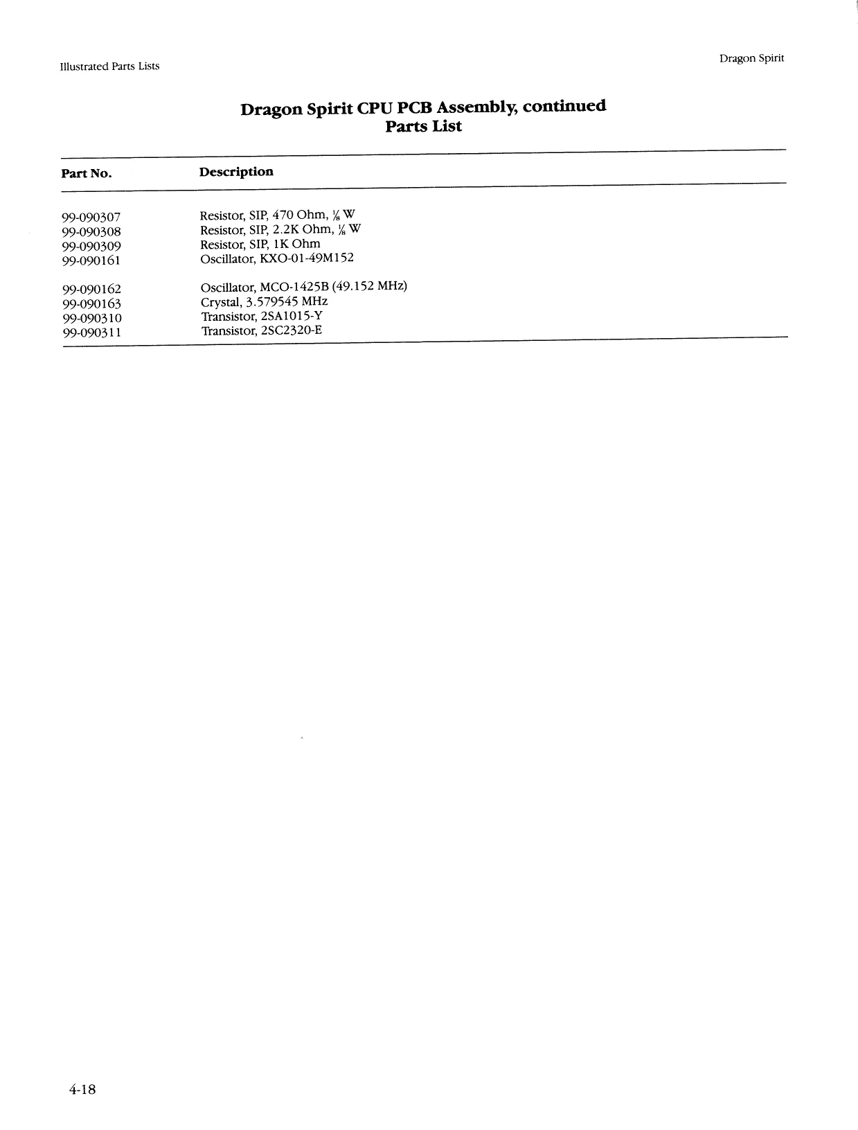
99-090111 IC, 74LS08 99-090114 IC, 741832 99-090115 IC, 741874 99-090120 IC, 74LS157 99-090122 IC, 74LS173 99-090124 IC, 7418245 99-090125 IC, 74LS257 99-090245 IC, 74LS365 99-090130 IC, 74LS377 99-090131 IC, 7418378 99-090288. IC, 74F04 99-090289 IC, 74F08 99-090290 IC, 74HC86 99-090291 IC, 74HC175 99-090292 IC, 74HC646 99-090133 IC, 4069
99-090135, IC, 68A09EP 99-090134 IC, HDG8A09E 99-090136 IC, TMM2018D-45 (45 ns) 99-090293 IC, TMM2064P-150 (150 ns) 99-090294 IC, M5M5165P-120 (120 ns) 99-090141 IC, TMM2064P-10 (100 ns) 99-090140 IC, M5M5165P-10 (100 ns) 99-090295, IC, TMM2018D-55 (55 ns) 99-090142 IC, M5M5165-70 (70 ns) 99-090146 IC, TMM2064P-70 (70 ns) 99-090295 IC, TMM2018D-55 (55 ns) 99-090142 IC, M5M5165-70 (70 ns) 99-090296 IC, M5M5256AP-70 (70 ns) 99-090297 IC, HM65256BP-150 (150 ns) 99-090298 IC, HM62256P-150 (150 ns) 99-090299 IC, PAL, 16L8B-2 99-090147 IC, YM2151 99-090148 IC, Custom 27 99-090149 IC, Custom 30 99-090150 IC, Custom 39 99-090154 IC, Custom 48 99-090300 IC, Custom 116 99-090301 IC, Custom 117 99-090302 IC, Custom 120 99-090303 IC, Custom 121 99-090304 IC, Custom 133 99-090194 Resistor, 4.7K Ohm, 5%, %4 W 99-090199 Resistor, Meg Ohm, 5%, 4 W 99-090262 Capacitor, Ceramic, 22 pF 12 V 99-090175 Capacitor, Ceramic, 0.1 pF, 25 V 99-090305 Resistor, SIP, 100 Ohm, ¥, W 99-090306 Resistor, SIP, 2.7K Ohm, 4 W
4-17
This page is a drawing, shown as the original scan.
Dragon Spirit Illustrated Parts Lists
Figure 4-6B Dragon Spirit ROM PCB Assembly 99-090287
Ilustrated Parts Lists Dragon Spirit
Dragon Spirit ROM PCB Assembly
Parts List
Part No. Description
99-090108 IC, 74LS00 99-0903 12 IC, 74F02 99-090117 IC, 74LS138 99-090118. IC, 74LS139 99-090244 IC, 7418244 99-090124 IC, 74LS245 99-090125 IC, 7418257 99-090126 IC, 7418273, 99-090127 IC, 74L8373 99-0903 13, IC, 74F138 99-090314 IC, 74F244 99-090315 IC, 74F374 99-090246 IC, 4066 99-090132 IC, 74HC257 99-0903 16 IC, 74HC374 99-0903 17 IC, Custom 64
99-090157 IC, Custom 99 99-090318 IC, Custom 123 99-090155 IC, Custom 95 99-090158 IC, DAC, YM3012 99-090319 IC, PAL, 16L8B-2 99-090320 IC, 78L06 99-090248 IC, Op-Amp, TLO84CN 99-090160 IC, Power Amplifier, LA4460 99-090321 IC, LA4520 99-090322 IC, TA7630 99-090323 IC, LB1760 99-090324 IC, MB3771 99-090250, Diode, 181588 99-090325 Diode, 151885 99-090326 Diode, 126.2 99-090327 ‘Transistor, 2SC1815 99-090310 Transistor, 2SA1015-Y 99-090328, Transistor, 25C2236-Y 99-090187, Resistor, 4.7 Ohm, 5%, 4 W 99-090255 Resistor, 100 Ohm, 5%, 4 W
99-090189 Resistor, 330 Ohm, 5%, 4 W 99-090191 Resistor, 470 Ohm, 5%, 4 W 99-090192 Resistor, 560 Ohm, 5%, 4 W 99-090329 Resistor, 1.5K Ohm, 5%, 4 W 99-090257 Resistor, 2.2K Ohm, 5%, 4 W 99-090194 Resistor, 4.7K Ohm, 5%, 4 W 99-090195 Resistor, 6.8K Ohm, 5%, 4 W 99-090196 Resistor, 1OK Ohm, 5%, 4 W 99-090330 Resistor, 12K Ohm, 5%, 4 W 99-090200 Resistor, 18K Ohm, 5%, 4 W 99-090261 Resistor, 47K Ohm, 5%, 4 W 99-090331 Resistor, 100K Ohm, 5%, 4 W
4-20
Illustrated Parts Lists Dragon Spirit
Dragon Spirit ROM PCB Assembly, continued Parts List
Part No. Description
99-090199 Resistor, Meg Ohm, 5%, 4 W 99-090332 Resistor, SIP, 1K Ohm, ¥, W 99-090333 Resistor, SIP, 1.2K Ohm, 4 W 99-090334 Resistor, SIP, 1K Ohm, 4 W
99-090185 Resistor, SIP, 4.7K Ohm x 8, 4 W 99-090335 Resistor, SIP, 10K Ohm, % W 99-090336 Resistor, SIP, 1OK Ohm, % W 99-090253 Resistor, SIP, 5K Ohm x 8
99-090274 Inductor, 100 4H, SP0406-101K 99-090337 Capacitor, Cer, 2200 pF, 25 V 99-090174 Capacitor, Ceramic, 0.01 pF, 25 V 99-090175, Capacitor, Ceramic, 0.1 pF, 25 V 99-090338 Capacitor, .0047 pF, 50 V 99-090339 Capacitor, .033 E50 V 99-090340 Capacitor, 12 hE, 50 V 99-090341 Capacitor, .01 wF, 50 V 99-090342 Capacitor, 1 pF, 25 V 99-090343 Capacitor, Electrolytic, 47 uF, 66.3 V 99-090344 Capacitor, Electrolytic, 470 uF, 10 V 99-090345 Capacitor, Electrolytic, 2.2 pF, 16 V
99-090346 Capacitor, Electrolytic, 4.7 pF, 16 V 99-090269 Capacitor, Electrolytic, 10 pF, 16 V 99-090347 Capacitor, Electrolytic, 22 pF, 16 V 99-090270 Capacitor, Electrolytic, 47 pF, 16 V 99-090348 Capacitor, Electrolytic, 220 pF, 16 V 99-090349 Capacitor, Electrolytic, 1000 uF, 16 V 99-090350 Capacitor, Electrolytic, .47 uF, 50 V 99-090351 Potentiometer, 10K Ohm 99-090352 Switch, DIP, 8-Circuit 99-090255 Resistor, 100 Ohm, 5%, 4 W 136055-1101 IC, ROM, Dragon Spirit, DS PRG-0, H10 136055-1102 IC, ROM, Dragon Spirit, DS PRG-1, K10
136055-1103 IC, ROM, Dragon Spirit, DS PRG-2, L10 136055-1104 IC, ROM, Dragon Spirit, DS PRG-3, M10 136055-1105 IC, EPROM, Dragon Spirit, DS1 P4, N10 136055-1106 IC, EPROM, Dragon Spirit, DS1 P5, PIO
136055-1107 IC, EPROM, Dragon Spirit, DS1 P6, $10 136055-1108 IC, EPROM, Dragon Spirit, DS1 P7, T10 136055-1109 136055-1110
136055-1111 136055-1112 136055-1113 136055-1114 IC, EPROM, Dragon Spirit, DS1 SO, A10 IC, EPROM, Dragon Spirit, DS1 S1, B10
IC, ROM, Dragon Spirit, DS OBJ-0, A9 IC, ROM, Dragon Spirit, DS OBJ-1, B9 IC, ROM, Dragon Spirit, DS OBJ-2, E9 IC, ROM, Dragon Spirit, DS OBJ-3, F9
Ilustrated Parts Lists Dragon Spirit
Dragon Spirit ROM PCB Assembly, continued Parts Lists
Part No. Description
136055-1115 IC, ROM, Dragon Spirit, DS OBJ-4, H9 136055-1116 IC, ROM, Dragon Spirit, DS VOLO, A4 136055-1117 IC, ROM, Dragon Spirit, DS VOI-1, B4 136055-1118 IC, ROM, Dragon Spirit, DS VOI-2, E4
136055-1119 IC, ROM, Dragon Spirit, DS VOL-3, F4 136055-1120 IC, ROM, Dragon Spirit, DS VOI-4, H4 136055-1121 IC, ROM, Dragon Spirit, DS CHR-O, A8- 136055-1122 IC, ROM, Dragon Spirit, DS CHR-1, B8
136055-1123 IC, ROM, Dragon Spirit, DS CHR-2, E8 136055-1124 IC, ROM, Dragon Spirit, DS CHR-3, F8 136055-1125 IC, ROM, Dragon Spirit, DS CHR-4, H8 136055-1126 IC, ROM, Dragon Spirit, DS CHR-5, K8
136055-1127 IC, ROM, Dragon Spirit, DS CHR-6, L8 136055-1128 IC, ROM, Dragon Spirit, DS CHR-7, M8 136055-1129 IC, ROM, Dragon Spirit, DS CHR-8, U8
Dragon Spirit
NOTICE TO ALL PERSONS RECEIVING THIS DRAWING CONFIDENTIAL: Reproduction forbidden without the specific written permission of Atari Games Corporation, Mipitas, CA. This drawing is only Conditionally issued, and neither recep nor possession thereof confers or transfers any right in, oF license lo use, he subject matte’ ol the Grawing, Or any design oF technical information shown thereon, nor any right to reproduce this drawing or any part thereo!, Except for manutacture by vendors of Atan Games Corporation, and for manufacture under the corporation's writen license, no right is granted to reproduce ths drawang Or the subject matter thereof, unless by watfen agreement wath or watten permission from the corporation IMlustrated Parts Lists
ci bas 299999 20) 2% seeeeeee? on oe
Te | oa. ae CONTROL 2. A jpeoocccee be} ; a woe Ot Ato
v2
& SELF TEST
SERVICE ‘sw
LIFIITITILITILET IIIT RI +o 9 R7 ~ 8 ecoccce °° 5 31 ‘ VIDEO Re v3
Lg 4 $6505 belle a tl a cocccd COIN ‘PKR 333322 -
a Figure 4-7 End PCB Assembly A044201-01 A
End PCB Assembly Parts List
Designator Description Part No.
Capacitors c1-C21 1 ¢E, 50 V Ceramic Capacitor 122002-104
C32, C33 C34-C36
CRI, CR2
R8
L1-L3 cc+,CC+ TP3 001 pE, 50 V Ceramic Capacitor 470 pF, 100 V Ceramic Capacitor 1 wE, 50 V Ceramic Capacitor 01 pF, 25 V Ceramic Capacitor 1 wE, 50 V Ceramic Capacitor Diodes Type-1N4001 Diode Connectors 11-Ckt., .1-Inch Cur, Header Connector 6-Ckt., .156-Inch Ctr. Header Connector 9-Ckt., .156-Inch Ctr. Header Connector 6-Ckt., .1-Inch Ctr. Header Connector 56-Ckt., Right-Angle Edge Connector (Acceptable substitute is part no 179240-156) Resistors OQ, 45%, % W Resistor Miscellaneous Ferrite Bead Test Point, .187 x .031 Test Point, .250 x .031 SPDT Miniature Slide Self-Test Switch 2-Ckt., .1-Inch Ctr, Header Connector (Service Switch) 122002-102 122016-471 122002-104
122005-103 122002-104
131048-001
179118-011 179213-006 179213-009 179118-006 179240-056
110005-001
141003-005 179051-001 17905 1-003 160040-001 179118-002
4-23
Ilustrated Parts Lists Dragon Spirit
N O T E S
4-24
AC Alternating current; from zero it rises to a maximum positive level, then passes through zero again to a maximum negative level.
ACTIVE STATE The true state of a signal. For example: The active state for START is low.
ADDRESS A value that identifies a specific location of data in memory; normally expressed in hexadecimal notation.
ANALOG Measurable in an absolute quantity (as opposed to on or off). Analog devices are volume controls, light dimmers, stereo amplifiers, etc. ANODE The positive (arrow) end of a diode. AMPLIFIER A device used to increase the strength of an applied signal. AMPLITUDE The maximum instantaneous value of a waveform pulse from zero. ASTABLE Having no normal state. An astable device will free-run or oscillate as long as operating voltage is applied. The oscillation frequency is usually controlled by external circuitry. AUXILIARY COIN SWITCH A momentary-contact pushbutton switch with a black cap located on the utility panel. The auxiliary coin switch adds credits to the game without activating a coin counter. BEZEL A cut, formed, or machined retention device, such as the conical device used to mount a pushbutton switch to a control panel, or the formed device used to frame the video display screen. BIDIRECTIONAL Able to send or receive data on the same line (e.g., the data bus of a microprocessor). BINARY A number system that expresses all values by using two digits (0 and 1). BIT A binary digit; expressed as 1 or 0. BLANKING ‘Turning off the beam on a cathode-ray tube during retrace. BLOCK DIAGRAM A drawing in which functional circuitry units are represented by blocks. Very useful during initial troubleshooting. BUFFER 1, An isolating circuit designed to eliminate the reaction of a driven circuit on the circuits driving it (e.g., a buffer amplifier).
- A device used to supply additional drive capability. BUS An electrical path over which information is transferred from any of several sources to any of several destinations. CAPACITOR A device capable of storing electrical energy. A capacitor blocks the flow of DC current while allowing AC current to pass. CATHODE The negative end of a diode. CHIP An integrated circuit comprising many circuits on a single wafer slice. CLOCK A repetitive timing signal for synchronizing system functions. COINCIDENCE Occurring at the same time. COIN COUNTER ‘A G-digit electromechanical device that counts the coins inserted in the coin mechanism(s). COIN MECHANISM A device on the inside of the coin door that inspects the coin to determine if the correct coin has been inserted. COMPLEMENTARY Having opposite states, such as the outputs of a flip-flop. COMPOSITE SYNC Horizontal and vertical synchronization pulses that are bused together into a single signal. This signal provides the timing necessary to keep the display in synchronization with the game circuitry. COMPOSITE VIDEO Complete video signal from the game system to drive the display circuitry, usually comprising H SYNC, V SYNC, and the video.
Glossary
CREDIT One play for one person based on the game switch settings. CRT Cathode-ray tube. DATA General term for the numbers, letters, and symbols that serve as input for device processing. DARLINGTON A two-transistor amplifier that provides extremely high gain. Dc Direct current, meaning current flowing in one direction and of a fixed value. DEFLECTION YOKE Electromagnetic coils around the neck of a cathode-ray tube. One set of coils deflects the electron beam horizontally and the other set deflects the beam vertically. DIAGNOSTICS A programmed routine for checking circuitry. For example: the self-test is a diagnostic routine. DIODE A semiconductor device that conducts in only one direction. DISCRETE Non-integrated components, such as resistors, Capacitors, and transistors. DMA Direct memory access. DMA is a process of accessing memory that bypasses the microprocessor logic. DMA is normally used for transferring data between the input/output ports and memory. DOWN TIME The period during which a game is malfunctioning or not operating correctly due to machine failure.
EAROM Electrically alterable read-only memory (see ROM). The EAROM is a memory that can be changed by applying high voltage. EPROM Erasable programmable read-only memory (see ROM). FLYBACK A step-up transformer used in a display to provide the high voltage.
gl-l
GATE
- A circuit with one output that responds only when a certain combination of pulses is present at the inputs.
- A circuit in which one signal switches another signal on and off.
- To control the passage of a pulse or signal HARNESS A prefabricated assembly of insulated wires and terminals ready to be attached to a piece of equipment HEXADECIMAL A number system using the equivalent of the decimal number 16 as a base, The symbols 0-9 and A-F are usually used.
HISTOGRAM A special type of bar graph that shows how quantities are distributed. Histograms are included in the self-test of most Atari games, and typically show how long players play that game. Ic Integrated circuit. An electronic circuit in which all elements and the connections are made in or on a single semiconductor substrate. See also chip. IMPLODE To burst inward; the inward collapse of a vacuum tube
Vo Input/Output, IRQ Interrupt request. IRQ is a control signal to the microprocessor that is generated by external logic. This signal tells the microprocessor that external logic needs attention. Depending on the program, the processor may or May not respond. LED The abbreviation for a light-emitting diode.
LOCKOUT COIL Directs coins into the coin return box when there is no power to the game. LOGIC STATE The binary (1 or 0) value at the node of a logic element or integrated circuit during a particular time. Also called the logic level. The list below shows the voltage levels corresponding to the logic states (levels) in a TTL system, Logic 0, Low = OVDC to +0.8 VDC Grey Area (Tri-State Level) = +0.8 VDC to + 2.4 VDC Logic 1, High = +2.4VDC to +5 VDC MULTIPLEXER A device that takes several low-speed inputs and combines them into one highspeed data stream for simultaneous transmission on a single line. NMI Non-maskable interrupt. NMI is a request for service by the microprocessor from external logic. The microprocessor cannot ignore this interrupt request
PAGE A subsection of memory. A read-only memory device (see ROM) is broken into discrete blocks of data. These blocks are called pages. Each block has X number of bytes PCB ‘The abbreviation for a printed-circuit board
PHOTOTRANSISTOR A transistor that is activated by an external light source. POTENTIOMETER
- A resistor that has a continuously moving contact which is generally mounted on a moving shaft. Used chiefly as a voltage divider. Also called pot (slang).
- An instrument for measuring a voltage by balancing it against a known voltage. RAM Random-access memory. A device for the temporary storage of data
RASTER-SCAN DISPLAY A display system whereby images are displayed by continuously scanning the cathode-ray tube horizontally and vertically with an electron beam. The display system controls the intensity of the electron beam. RETRACE Ina raster-scan display, retrace is the time during which the cathode-ray tube electron beam is resetting either from right to left or from bottom to top RESISTOR A device designed to have a definite amount of resistance. Used in circuits to. limit current flow or to provide a voltage drop ROM Read-only memory. A device for the permanent storage of data SIGNATURE ANALYSIS A process of isolating digital logic faults at the component level by means of special test equipment called signature analyzers. Basically, signature analyzers (e.g., the ATARI® CAT Box) convert lengthy bit streams into four-digit hexadecimal signatures. The signature read by the analyzer at each circuit node is then compared with the known good signature for that node. This process continues until a fault is located.
TROUBLESHOOT The process of locating and repairing a fault
VECTOR A line segment drawn between specific X and Y coordinates on a cathode-ray tube
WATCHDOG A counter circuit designed to protect the microprocessor from self-destruction if a program malfunction occurs. If a malfunction does occur, the counter applies continuous pulses to the reset line of the microprocessor, whi causes the microprocessor to keep. resetting, X-Y DISPLAY A display system whereby images are displayed with vectors ZENER DIODE
A special diode used as a regulator. Its
main characteristic is breaking down at a specified reverse-bias (Zener) voltage.
Warranty
Seller warrants that its printed-circuit boards and parts thereon are free from defects in material and workmanship under normal use and service for a period of ninety (90) days from date of shipment. Seller warrants that its video displays and laser video disc pI: s(in games supplied with displays and video-disc players) are free from defects in material and workmanship under normal use and service for a period of thirty (30) days from date of shipment. None of the Seller’s other products or parts thereof are warranted. If the products described in this manual fail to conform to this warranty, Seller's sole liability shall be, at its option, to repair, replace, or credit Buyer's account for such products which are returned to Seller during said warranty period, provided:
- Seller is promptly notified in writing upon discovery by Buyer that said products are defective;
- Such product
- Seller’s examination of said products discloses to Seller's satisfaction that such alleged defects existed and were not caused by accident, misuse, neglect, alteration, improper repair, installation, or improper testing. are turned prepaid to Seller's plant; and
In no event shall Seller be liable for loss of use, incidental or consequential damages. of profits, Ic
Except for any express warranty set forth in a written contract between Seller and Buyer which contract supersedes the terms herein, this warranty is expressed in lieu of all other
sssed or implied, including the implied warranties of merchantability and
for a particular purpose, and of all other obligations or liabilities on the Seller’s part, and it neither assumes nor authorizes any other person to assume for the Seller any other liabilities in connection with the sale of products by Seller.
y non-Atari parts may void your warranty, according to the terms of the waraffect the safety of your game and upplied components The use of an’ ranty. The use of any non-Atari parts may also adversely cause injury to you and others. Be very cautious in using non-Atari-s with our games, in order to ensure your safety. Atari distributors are independent, being privately owned and operated. In their judgment they may sell parts or accessories other than Atari parts or accessories. Atari Games Corporation cannot be responsible for the quality, suitability or safety of any non-Atari part or any modification including labor which is performed by such distributor.
This page carries no recoverable text. It is a drawing or a photograph. See the original scan.