Battlezone DP-156-2nd-01B
Battlezone (rev 2) (Atari, 1980) · Drawing Package · 1 pages · original scan
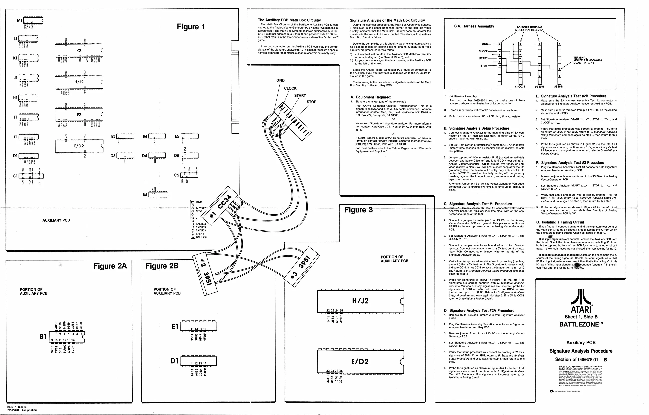
The Auxiliary PCB Math Box Circuitry Signature Analysis of the Math Box Circuitry . ‘The Math Box Circuitry ofthe Battlezone Auxifary PCB is con During the softest procedure, the Math Box Circuitry s quized.
| Figure | 1 | nected tothe Analog Vector Generator BCB va the PCB harness | T displayed in the upper ighthand comer | of the selttest video | S.A. Harness Assembly | +2¢1RCUIT HOUSING |
| terconnector. The Math Box Circuitry receives addresses EABO thru | display indicates that the Math Box Circuitry does not answer the | MOLEX P.N. 09-50-7121 |
ABS (extemal address bus 0 thru 4) and proves data EDEO thru _—_question inthe amount of time expected. Therefore, aT ncicates a
| nT | . | . | DB7 thal results inthe three-dimensional video ofthe attlezone™ — | Math Box Circuitry fale, | ||||||||
| : | GHORSAAAAAAAEAAASAaA, | Due to the complexity ofthis circuitry, we offer signature analysis | GND— | = | 7 | |||||||
| i | + | : | A second connector on the Auxiliary PCB connects the control | as a simple moans of iolting fling circuit. Signatures for this | ia | |||||||
| K2 | signals of the signature analyzer (SA). This header accepts a special | circuitry are presented in two forms: | ‘clock. | te] | ||||||||
| — | | | S | hamess connector that makes signature analysis extremely easy. | 4) | atthe actual test points in the Auxiliary PCB Math Box Circuitry | | | q | |||||
| ee | Schematic diagram (on Sheet 3, Side 8), and | ant | 4 | TERMINAL | ||||||||
| Ti | | | to the lft ofthis text, | Li | Quan | 38 | |||||||
| 2883 | 1 | stop—— | [ot4 | eH | _| | |||||||
| H | ‘Since the Analog Vector-Generator PCB must be connected to | iJ | ||||||||||
| i | | | the Aunilay PCB, you may take signatures while the POBS ar in | | | C | ||||||||
| i Cse | = | : | stalled inthe game, | a | H | tal | ||||||
| HH | H/J2 | a | ‘Tne following isthe procedure for signature analyls ofthe Math | a | Hy | O | ||||||
| HE | a | Box Cireuitry ofthe Auxiliary PCB: | UO | fice | eosi | nant | ||||||
| ‘A. Equipment Required: | 2. | SA Hames Assembly | E. Signature Analysis Test #2B Procedure | |||||||||
| 4. | eeaie Anca ne cf te owineh | ‘Atari part number A03680601. You can make one of these | 1. | Make sure the SA Harness Assembly Test #2 connector is | ||||||||
| rset, Above isan ilustration ofits construction. | lagged | onto Signature Analyzer neader on AUxllary | PCB. | |||||||||
| Atari C*A*T Computer-Assisted Troubleshooter. This is a | bi | Planar | * | si | vt | |||||||
| signature analyzer and a RAMIROM tester combined. For more. | ‘Three | jumper | wires with “hook” connectors on each er | ‘Make | sure | jumper | is removed from pin 1 of IC B6 on the Anal | |||||
| information contact Ala, ne. Feld SerielCoinOp Dison, | 4 | Tegel | Wie | ht Re | connect | te | ® | MocorSenartor PCB, | om hn | ToH1C | BS onthe | Analog |
| 0 Box 427, Sunnyale, CA S486. | 4, | Pullp esatras follows: 1K to 15K ohm, 4 watt resistor. |
oR Set Signature Analyzer START to_/~, STOP to “Land KureKasch Signature II signature analyzer. For more informa: CLOCK to“.
| tien oo NM | Ta | Signature Analysis Setup Procedure | 4. | Verify that setup procedure was correct by probing +5V for a | ||||||||
| —— | = | al | 1. | Connect Signature Analyzer to the matching pins of SA con- | signature of 2961. If not 3951, return to B. Signature Analysis | |||||||
| ras | 5 [, | rector on the SA Harness assembly. In other words, GND | ‘Setup Procedure and once agaln do stop 3, then return to this | |||||||||
| [Le | - | HowiottPackard Model | SOO4A signature analyzer. For more in | Tees Cas wien oe | ston | |||||||
| : | : | formation contact Hewet Packard, Sclentic instruments DN, | ||||||||||
| 8 | id | 1501 Page Mil Road, Pal Alto, CA S430, | 2: | Sot Solt-Test Somen of pannezona™ pam 19 ON: Aner Spor | robe for sgnatures a8 shown in Figure #28 to the et If al | |||||||
| 3 | For local dealers, check the Yellow | Pages | under | “El | imately three seconds, the TV monitor should display the self- | signatures are correct, continue with F. Signature Analysis Test | ||||||
| _ | i | Eos cel dir, check te | Yalow | Fagen | ender | “loonie | Inala | ee | secon | ly | Spends ie sitae sere. eo | eine |
| D4 | ps [,° | i |
3, Jumper top end of 1K-ohm resistor R129 (located immediately between and below C [center] and L eft] COIN test points) of ‘Analog VectorGenerator PCB to ground five times, or until video display is blank. You will hear a short beep after the Sth ‘grounding; also, the screen will display only a tiny dot in its Center. NOTE: To avoid accidentally turning off the game by ‘brushing against the interlock switch, we recommend putting tape over the switch. ‘Altemate: Jumper pin 5 of Analog Vector-Generator PCB edge- ‘connector J20 to ground five times, or until video display is . Signature Analysis Test #3 Procedure Plug SA Hamess Assembly Test #3 connector onto Signature ‘Analyzer header on Auxiliary PCB. ke sure jumper is removed from pin 1 of IC B6 on the Analog Vector Generator PCB. ‘Set Signature Analyzer START to_/— , STOP to. and blank. CLOCK to. | 4. Verily that setup procedure was correct by probing +SV for 3951. If not 3961, retuin to B. Signature Analysis Setup Pro- ‘cedure and once again do step 3, then retum to this step. C. Signature Analysis Test #1 Procedure
| 4 Plug-SA Harness Assombly Test #1 connector onto Signal | 5. | Probe for signatures a8 shown in Figure 43 to the lft. If all |
Analyzer header on Auxiliary PCB (the black wire on the con: signatures are correct, then Math Box Circuitry of Analog rector should be atthe top. Vector Generator PCB Is OK AUXILIARY PCB [ooo o0000000m
2. Connect a jumper between pin 1 of IC 88 on tho Anal
| VectorGenerator PCB and ground. Tis places a continuous | -—-G. | ISolating a Failing Circuit |
RESET tothe mlroprovessor onthe Aralog Vector Generator you ind an nce signature, id the signature test point of Pe tho ath Box Greuity on Shot 3, Sido 8. Locate tho fom which the slgnatur eben output Chock a inputs of tat
- Set Signature Analyzer START to, STOP to, and
| Cock too | tan ng inatrs are comet: Remove the Aula | PCB rom |
thot Check tho cet trace common tothe fang © inn
| 4. | Connect a jumper wi to each end of a 1K to 18K ohm | —_buth the top and baton ofthe PCB for shorts to another ctl |
fetter Gonnott one joper wir (0 +3V test pont on Aix’ _tacell hochoult vac ae ot shored tan replace Ie ang Hiary POB. Connect other jumper wire to the tip of the ‘Signature Analyzer probe. It an input signature is incorrect: Locate on the schematic the IC PORTION OF soure ofthe fling signature. Check the Input signatures ofthat
| AUXILIARY PCB | 5 | Verity that setup procedure was corect by probing ouching | [Gal | ng signature ae comec, then tals the faling Chis | |||
| ; | Fi | 2A | Fi | 2B | probe to) the SV test pont. The Signature Analyzor should | ICs fling input signature | continue “upstream in the cr. |
| igure | igure | Pec Leh vetoes holamperer octets | fopmrtnmlneut lana |
- Rtum to 8. Signature Anlyts Setup Procedure and once again oo step 2.
| 6. | Probe for signatures as shown in Figure | 1 to the left. If all |
signatures are correct, continue with D. Signature Analysis Test #2A Procedure. If any signatures are incorrect, probe for
| PORTION OF | PORTION OF | SoSooo | ooo | ee of coe ontey test ot. | ai Cots | morn |
| lumper from pin ol | um to B. | Signature | -Analyels | |||
| AUXILIARY'PCB | ‘AUILIARY PCB | Setup Procedure and once again do stop | ll +S (3 C684, |
H/J2 rolerto &.lolting a Pang Creu 22 23 2425 D. Signature Analysis Test #2A Procedure ATARI
| prt | 1 | Repo 1K | ohm ampere fom Slate An | Sheet 1, Side B |
sefeass ERae ™,
| BSBSkSes | 2. | Plug | SA Harness Assembly Test #2 conne | nto | Signature | T T |
| S2Se3e8 | El | Analyzer header on Aualiany BOB. | nsw ono | Snare | BATTLEZONE | |
| esa oe | 2. | Remove jumper from pin 1 of 16 88 on the Analog Vector |
Generator PCB.
| 9 | 4. | Set Signature Analyzer START to_/— , STOP to “L, and | Auxiliary PCB |
f&esses Clock to
| S8s2S5 | 5, | Verity that setup procedure was correct by probing +5V for a | Signature Analysis Procedure |
signature of 3951. If not 9951, retum to B. Signature Analysis. Setup Procedure and once again do step 3, then return to this step. Section of 03567801 B DI
| egee | 6. | Probe for signatures as shown in Figure #2A to the lft. If all | msomeascemmeeecnars |
eege signatures are correct, continue with &. Signature Analysis. S<sr Test #2B Procedure. \\ a signature is incorrect, refer to G. Isolating a Falling Circut
ee ‘Sheet 1, Side B DP-15601 2nd printing