Head-On
Head On (2 players) (Gremlin, 1979) · Manual · 47 pages · 33 sections · original scan
@aRT NO. 420-01 93 MANUFACTURED BY
Industries, inc.
©
OWNERS MANUAL
HEAD ON
OPERATING INSTRUCTIONS
AND
SERVICE MANUAL
HEAD ON OWNER'S MANUAL
Copyr ight(C)1979 by Gremlin Industries, Inc. All Rights Reserved
All the information contained herein is the exclusive proprietary property of GREMLIN INDUSTRIES and is disclosed in confidence and may not be duplicated nor copied in whole or part, nor be used for any purposes other than that for which disclosed.
TABLE OF CONTENTS
Page INTRODUCTION 1
REPACKAGING INSTRUCTIONS 3
GAME CONCEPT 4
MAINTENANCE PROCEDURES 6
TRANSFORMER VOLTAGE CONVERSION INSTRUCTIONS 8
SCHEMATICS Following Pages
INTRODUCTION
This is an electronic game that makes extensive use of digital integrated circuitry and television monitor circuitry. This manual assumes the maintenance technician possesses a general knowledge of solid state circuitry,microprocessor, TTL digital integrated circuitry and T.V. monitor concepts. Any individual NOT knowledgeable in these areas SHOULD NOT attempt repair of the electronic portion of this game. IT SHOULD BE NOTED THAT ANY ATTEMPT TO REPAIR THE GAME IN THE FIELD WITH- OUT EXPRESS CONSENT OF THE FACTORY WILL IMMEDIATELY VOID THE WARRANTY:
NEVER replace any components with anything other than exact replacement parts. (See Parts List located on Service Schematics.
NEVER remove circuit boards/connections while power is on.
DO NOT replace the fuse with anything other than the proper value. A blown fuse indicates an overload condition within the game. Replacing the fuse with a higher value can cause severe damage to internal components if an overload occurs.
ALWAYS consult the manual before attempting repairs.
CORRESPONDENCE regarding this game should be addressed to:
GREMLIN INDUSTRIES, INC.
8401 Aero Drive
San Diego, California 92123
(714) 277-8700
An important service note is posted in this game and is repeated here for emphasis:
|F AT ANY TIME THE T. V. SCREEN SHOWS A MEANINGLESS DISPLAY
OR THE GAME OTHERWISE MALFUNCTIONS, SIMPLY DROP A COIN INTO
THE COIN MECHANISM. THIS SHOULD CORRECT THE PROBLEM. IF
NOT, THE GAME REQUIRES SERVICE.
The circuitry in this game has been arranged so that the insertion of a quarter through the coin mechanism will reset the system. This clears up temporary problems caused by power line disturbances, static, etc.
SERVICE TECHNICIAN NOTE:
The system reset circuitry described above requires that the coin counter is attached to the system. If there is a coin counter problem and no replacement is available, the game will function properly if a 10K Ohm resistor is connected across the coin counter input pins to the video logic board.
REPACKAGING INSTRUCTIONS
Should it be necessary to ship this game, follow the instructions below for game recrating:
A) If the original shipping bolts have been discarded (Ref.1), obtain four 5/16-18x1 3/4!' hex head bolts with 5/16" flat washers. Carefully lay the game on its side and attach skid (Ref.2).
B) Place game upright. Tape game keys to upper flange of operator's panel (Ref.3). Crate the game using appropriate shock-absorbent packing material (Ref.4). Include padding on all four corners of the game (Ref.5). After crating is completed, secure package with strapping (Ref.6).
GAME CONCEPT - HEAD ON
HEAD ON is a single-player video driving game. A player steers his car around the screen track, gaining as many points as possible in the time allotted. By maneuvering his car through the lanes, the player erases the markers in each lane for high score. But, the game has an additional element of challenge- the computer's car. It also moves around the track, in the opposite direction, and presents a test of skill by challenging the player to
outsmart its moves and avoid a crash.
Both the player's car and the computer's car (it's the hollow one) start at the bottom of the screen. As the player moves his car around the track, he clears the lane markers and adds points to his score. He must judge which lane to stay in or move to, depending on where the computer's car is. With the control panel joystick and accelerator button, the player controls not only his car's speed, either fast or slow, but also the number of lane changes he can make. For example, the player sees he can avoid the other car by making a lane change. Depending on how fast he is moving, the player can maneuver his car to change one or two lanes. If the car is moving fast, the player can make only one lane change; at slow speed, two lane changes are possible. Play continues in this manner, with the player continually trying to predict where the computer car will go, so that the two cars won't crash. If they do, the game resets the cars to the starting line and the lane markers reappear. The player again tries to clear as many lane markers as possible before time runs out. While game time is 90 seconds, play continues after that time to allow the player a last chance to clear any remaining lane markers. If he does this, the game gives a bonus time of 30 seconds. If he crashes, the game ends. The bonus time is awarded any time the player clears all the lane markers without crashing.
Each lane is given a point value, as shown in the track infield. At game start, each lane is worth 5 points. This value increases by 5 points each time the player clears all the lane markers. Also, the three highest scores to date are displayed on the track infield.
GAME CONCEPT cont'd.
As mentioned above, the computer's car adds challenge to the game action. At first, the player may have no difficulty avoiding the computer's car; but, as the game progresses, and the player's score increases, predicting which way the computer car will go becomes harder. This feature allows for a-variety of player skill levels.
HEAD ON is played with two controls- a joystick and push button. The joystick allows the player to make a lane change up, down, or left or right, depending on which part of the track his car is located. The push button controls the speed: Push down to move the car faster; release it to slow the car down.
HEAD ON has a complete set of sounds to highlight the action. Each car has its own engine sound; both the player's car and computer's car have different sounds for fast and slow speeds. Also, both cars produce a screech sound at each corner of the track, and when changing lanes. A sensational explosion occurs whenever the cars collide.
There are two options in HEAD ON: The number of coins per game (1,2,3,or 4) and, sound off during advertising. To select 2, 3, or 4 coins per game (the game is shipped in the 1 coin per game mode) a jumper is connected from ground {pin 10 on the player control connector on the logic board) to pin 3 for 2 coins per game, or to pin 4 for 3 coins. Both pins 2 and 3 are grounded for 4 coins per game. To turn off the advertising sound, simply turn the sound switch, located iinside |the coin door, to "'OFF''.
MAINTENANCE PROCEDURES- HEAD ON
I. Pi 1.
2.
1. OWER SUPPLY (refer to drawing #815-0020, sheet 4)
Remove output connectors from power supply. Make these initial tests: (GND to BLACK lead on c18, 9000 mfd cpacitor)
- +9 V DC on POSITIVE terminal of C18
- +17-19 V on C6 (4700 mfd. cap.)
- -17-19 V on C5 (4700 mfd. cap.)
- -12 V at pin 11 (adjustable by trim pot R42)
- +12 V at pin 12 (adjustable by trim pot R8 )
- +5 V at pins 18-20 (adjustable by trim pot R9)
- GND (ground, 0 V) at pins 14-16
- 2-3 V AC at pin 13 (Don't forget to change meter scale to AC) Check these voltages again with the logic board connected. If any are wrong, a loading problem exists in the logic board, most likely. Possible causes of a short on the logic board could be: U73, C21, C25, or C26.
SOUND BOARD (refer to drawing #822-0002, sheet 6)
If no sounds are produced:
- check connections between logic board (labelled '"'Sound Out") and Sound board (pins 1 through 14) and between the Sound board and the Power Supply.
- If they are good, check IC U16 on the logic board, pins 2,5,6,9,12, 15,16,and 19 for outputs when each sound is produced.
- If the outputs are present, check the output of the sound board, pin
- If the signals are present here (use an oscilloscope for best results) check the amplifier circuit on the power supply, specifically, U4, Q8, and Q9.
If some sounds are produced, but not all:
- repeat steps a and b, above.
- If these prove OK, check the specific circuit for each sound:
| SOUND TYPE: | SOUND BOARD PIN #: | CHECK THESE PARTS: |
| Crash | Pin 1 | Q2, U2, U1, U13 |
| High Speed | Pin 2 | Q8, U9, U8, U7 |
(computer car)
| Car on | Pin 3 | Q9, 6, U9, UI2, QI0, |
U6, U5
MAINTENANCE PROCEDURES- cont'd.
| High Speed | Pin 4 | Q12, QUO, U12, U6, U5 |
(player car)
| Screech #1 | Pin 6 | Q14, U10, D7 |
| Screech #2 | Pin 7 | Q13, U10, D6 |
| Bonus | Pin 8 | Q5, U4, U10, D8, C19 |
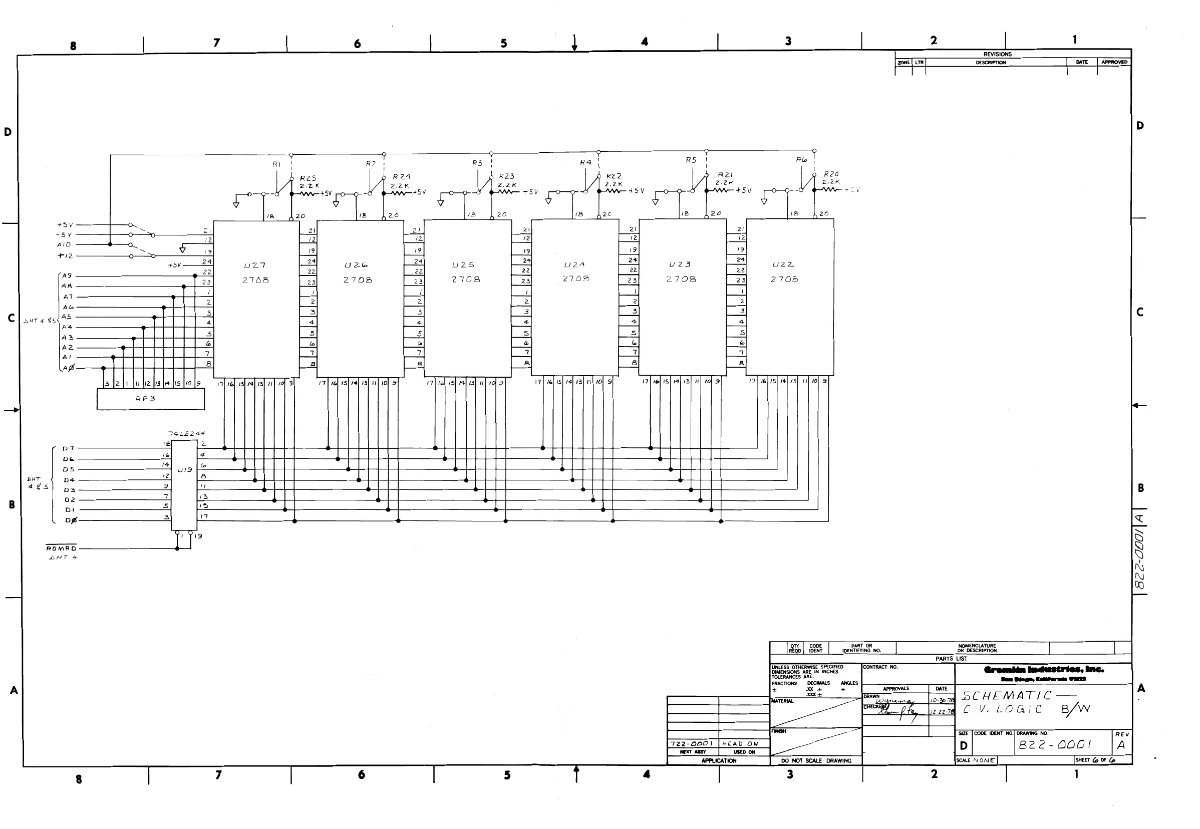
111. LOGIC BOARD (refer to drawing #822-0001, sheets 4,5, and 6)
- Game does not reset at power on: (see sheet 5) a)
No a) check connector pin 3 on logic board for 3 V AC signal. Also, check Q10, Q11, U55, U54, and U71. video: (see sheet 5) check U48 (part #315-0042)for video signals. Also, check U41, Q6 and Q7 for the video signals. Game does not coin: (see sheet 5) a)
b)
c)
d)
e)
+ No
a) b)
» No
a) Check coin switch connections to the logic board; make sure the coin switch is wired correctly.
Check U12, pins 3 and 11 for a pulse each time the coin switch is activated. Also, check U11 and U13.
Check also for the 4 msec. pulses at pin 7 of U10. These pulses serve as timing for the video circuit. Check also pin 5 of U11; pin6, U13. \f a game is started only occas .ionally,when a coin is deposited, the coin switch wire may need to be adjusted for a lighter, or heavier, tension. If the coin counter does not activate, check U12, pin 3 for a pulse each time the coin switch is activated; also, check QI and Q2. (see sheet 5)
@1 clock pulses to the microprocessor: (see sheet 4)
check for pulses at the crystal, Y1. check for pulses at pin 6 of U68; at pin 6 of U49; and at pin 4 of U54.
player control: (see sheet 5)
make sure the player control connections from the switches to the
MAINTENANCE PROCEDURES~ cont'd.
logic board are intact. Ensure that each switch is connected.
- If these are good, check for an output from U1 as you push each
switch.
- Random display on the screen:
- If the screen shows what appears to be a meaningless display, and it cannot be cleared by activating the coin switch, several different parts of the circuit should be considered:
One or more RAM's, U56 through U63 (sheet 5)
One of the programmed IC's, or EPROM's (sheet 6)Check their sockets. The reset circuit is not working.(see #1, above) The microprocessor is bad. (sheet 4) Data or address bus problem (e.g. U33 or U34, sheet 4, could be bad)
TRANSFORMER VOLTAGE CONVERSION INSTRUCTIONS:
To convert the game transformer to 100, 115, or 230 VAC, refer to the following chart:
For 100 Volts: Connect the voltage INPUT lines to terminals 1 and 2 on the transformer.
For 115 Volts: Connect the voltage INPUT lines to terminals 1 and 3.
For 230 Volts: Connect the voltage INPUT lines to terminals 1 and 4, with terminal 3 connected to the LAMP circuit.
Also, the TV monitor must be converted to the same voltage input as the game transformer. Refer to the monitor manual included in the game.
. | PARTS | TITLE 722-000! a ea TOP ASSY HEAD ON pw NO ae |LTR| DATE | Dear | CHECK | PR pA | | RELEASED aay It, ar FORM NO. 001-1500
TITLE SH2
TOP ASEY. HEAD ON A
OF § | REV
DESCRIPTION
Tor ASSY HEAD ON. PARTS 122-000)
LIST DWG NO
| QTY PER ASSY |
SPEAKER GAME
SPEAKER COVE
COVER JI-BoOx CABINET HEAD -ON MONITOR 19" Lec< COIN MECH. BEZEL SPEING RETAINER MOULDING CLIP SWITCH FRENT. CASH COCR MOP. PANEL MON. sce. FANEL LOGO CLIP WIkS CABLE TIE NUT WieceE LAMP FLOR. LAMP FIX. PECAL 4/N PECAL CAUTION II56Y DECAL IMPORTANT Note
TITLE
Gremlin Industries, Inc. ma a TOP ASEY HEAD -ON San Diege, California 92123
PART NO
QTY PER ASSY
DESCRIPTION
DECAL S/N SM.
DECAL TIP N TELL
INST CRATING
WRAP AROUND SIDE TOP COVER CORM. STRIP. MANUAL WELLS GAKRPNER. GRAPHIC SIDE LEFT GRAPHIC SIDE RIGHT GRAPHIC INTERIOR. MANUAL HEAD -ON B2KT SUPPORT CRT. J -BOX SPKR HARNESS COIN MECH HARNESS VID LOGIC BD. aN w
SOUND BD. HARNESS CONTIEOL PNL. HARNESS PWwe./SOUND JUMPER HARNESS MONITOR HARNESS Saldialalsla}s|s[sl slajsalalylsly/ ele) s/R SiR ase FORM NO. 001-1501
HABGNESS COIN CTE.
TITLE Gremiin Industries, Inc. PARTS TOP ASeY. HEAD-OK) SH4 A San Diege, Califernis 92123 OF 8 | REV
QTY PER ASSY PART NO 1 DESCRIPTION
PALET HEAD-CN 220-0008 COUNTER PIGITAL
SCR PHL PAN UD ¥ 6 X3/8° SUT MTL SCR,#% SUT, RD. WD. CRS REC lh SCR ¥8X'f2 SAT RD.AD PHL NUT HEX # 10-32 MACH SCR #8-32X 1¥z SLOT HD BOLT,CARRIAGE 10-24 X13/4 MACH. SCR 210-32 X 1.0 PAL PAN WASHER, LOCK, SPLIT #/0 ao Nn Q
WASHER, FLAT ¥8 WASHER, LOCK SPLIT 8 WASHER FLAT *\G NUT,HEX * 10-24 NUT, HEX * 6-32 NUT, WING 10-24 8-32 X 3/4 CRES TAMPER PROOF g & 2) & & & N Io iW) a fe] FORM NO. 001-1501
TITLE a [ast CONTIZOU. PANEL Asey | B22- A
DWG NO NO OF
REV LTR DATE |
- APPR
REVISION DESCRIP 10N
DRAFT | CHECK | APPR | FORM NO. 001-1500
PARTS | TITLE Gremlin industriesvine, | ic | CONTCOL PANEL Assy] B22- orp SH21 A
DWG NO OF 3 | REV
QTY PER ASSY
PART NO = DESCRIPTION REF DES
CONTROW PANEL. Ase. zn
CONTROL. PANEL /HEAD- ON BUTTON PLUNGER BLK. ew. ASEY WICO
ew. ASEY JOY STICK
GRAPHIC CONTIZOL PANEL CABG. BOUT S-2e@«"/2 Ak ozZce WAGHER FLAT *S NUT STD. HEX. 8-32 TAB 2VET SFACSE wico ow. VEE SUSE) S mG lo
GREMLIN IND ING TITLE SHI | A SAN DIEGO CA.92123] ASSY,POWER SUPPLY | 815-0020 4
DWG NO OF q | REV REVISION DESCRIPTION | prartT | CHECK | APPR | RELEASED prox’ | wife : SSD” SIZE SHT 4 18 ‘<¢@’S1ZE
a Title SH 2 Reo ca gicy EES ]ASSY, POWER SUPPLY | BIS- 0020 | ee |
DESCRIPTION CHASSIS, POWER SUPPLY 150-0022 CARE, 9OOONF 12V 2ll- QOOS CONN CRIMP LOCK 211- 0007 CONN, KEY , POLARIZING 211- OO'T CONN, QUICK, 1/4°FEM 211-0019 CONN, SPADE LUG 1/4” 212-0016 CONN, FEM 10 PIN 213-0006 SOCKET, TO-3 280 -OO1A STAND- OFFS, CLIPS . 280 - 0056 CLAMP, CAP. VR4_ 11/2” 481-0009 DIODE, MBA 3500 482-0007 XISTOR,2N3055 560-0003 XFMR.MODEL §-10345B 815-002) POWER SUPPLY ASSY (PCB) BIB- CO20
SCHEM. ASSY.PWR. SUPP. | CREFERANCE) SCREW-MACH P.HD86-32 KS NUT HEX #6-32 SCREW-MACH RD, HD 44-40 X37 NUT HEX # 4-40 | RIVET,POP 3/16 |SCR, MACH, HEX, WAS,HD 1/4-20 X SCR,MACH, PHD. %6-32%1.0"
BlS-00721 DWG NO
DESCRIPTION
PLR - Powe SuPPly CAP_E 47004uF,15V CAP. CER .oOSUF, DO GAP. CEL |IOOPF, SOV
CAP. CER .0Ol uF, SOV
EAP. CER. .01 uF, SOV | 012,614, CIL CAP, CE2, -luF, SOV CAP. TANT 1OWF, 25Y G1, 02,07, CIZ,US 150-0019 15\- 000)
J he|=[R]-[R CONN M_10 PIN) GONN M_ 4 PIN | 2 | 2, & a Ul
RIN 2(8
ic (M774 Us IC LM741 EN OI, U2, U4 RES 10o RX Jzw, 5% Res IK WL, Yew, S%__[€517,20,22- 24,36, 36,38, 34 Bes 10K, Aw, 5% | ei, e14, R21, R37 RES 100K, V2W) S% Res |-2EA, LW, S%e RED 1-5KN, RW) 5% RES Z.71KA, Yew, S% RES 3.3K, /2wW, S% 41, -0104 411 - 012%
SSSA A|N
parts [TITLE PC ASSY-
LIST POWER SUPPLY
[ OTY PER ASSY |
PART NO DESCRIPTION
4il- 2a "
| 4 | =
Bis-00721 [843 |B
DWG NO OF REF DES
Rid. ‘i
Bes 5.CE_L AW, 5% Res O-S L IW 1 S%e res Onl, sw, Veo 3BB
Por i TEIMMER For 2K TRIMMER Sams piobe Meso! Diope INA14 DIODE ZENE INSZS |
- |X| Gass
TEANSSTOR ZN4403 TRANSISTOR TIP IO TRANSISTOR 2N44o/ TEANSISTOR TIP INS TRANSISTOe TIP 24 aga im AE FS ST | S| \—t
FORM NO. 001-1500
TITLE TY PER ASSY PART NO g DESCRIPTION REF DES m N|~|% 751-00 CAP CER 10) pf SOV |C8,/3,17,32,2), 22 (51-0012 CAP CER of pF SOV 25,012,C26,C27 (52-0001 CAP FILM at pt 100V £3)C20,025 ul 152-O0/2 CAP FILM 047 pt 2O00V C2, 023,024 152- O0018|3. LAPFILM .Ot
f 250v | c3,CGt!9 152-0020 CAP FILM La T yf 100V C1, C18, Cl6 153-000! CAPTANT /8 pet 25V Cld,cl C28-C30,Cc3 153-0002 CAP TANT / nf 25V [533-0003 CLAP TANT 2 25V 153-0004 CAP TANT 4.7,f 25V 7 170-0154 + P@B HEAD ON SOUND + CONN M 12 PIN cS iS) tl
1C LM7T4!1 EN DIP 12 LM324+8 DIP [C NESS5 DIP 4013 4081 MM 5837 4049
PARTS | TITLE
HEAD ON SOUND
Gremiin industries, inc.
B2
DESCRIPTION
& REV
REF DES
F7l1-O10l
100 OHM 2W 5% 4F7I-O102
1K OHM i/2W 5%
R4,R5,RB,R14,R2Z2,R35 R45,R55,R72, R48 47(- O103
/OK OHM “2W 5%
RIO,RIZ,R13,R 25, R43,R46,R 50,R56-R6O RO4RG7ZRGB, R15 47/-O1lOF
100K OHM /1/2W5%
R15 —R21,R24,R 34,R 36 R41,R242,R 62,RE5,RGY R71,R16 47/-O!045
|] MEG OHM
RA,RIO.RIT 471-O!124
120K OHM 47/-O153
RES 15 K_OHM
R47, R5|1,R63,R6G F7/- O1S4
RES 150k OHM 471-0220
RES 22 OHM 471-OCZ24
RES 220K GHM \f2W5% 47/-O 294
RES 390 K OHM I/2W 5%
R2C6~R31,R44,R73 47/-O0472
4.7K OHM I72W 5%
R&G,R52,R 14 F7l~OF73
RES 47K OHM /2W 5%
R33 47/-D0474 us foo | —|~T N]~ G9] ny Alp
RES 470K OHM I/2W 5%
R9,RI 471-0682
RES Ge 3K OHM 1/2W 5%
R53,R54 A#AIS~OOOG NIN
POT 100K
R,R1 4ZB1- COOG
(23)
DIODE IN9/4/1N 4148
Dl-D8
PARTS | TITLE yo ine. ! yn c j - { Gremlin Industries, Inc. LIST HEAD ON Ss 0 UND 8 oe a A
QTY PER ASSY
DESCRIPTION REF DES
PART NO
482-00060/2 XSTR_ 2N440% 4@,G10 482-00 14/9 XSTR ZN440! 22,0 5,9 7-93,QII-g/4
XSTR_ 2N 4093 63,94 4232-0023|2 47/- 0O723|1 RES 22K OAM W/aw 5% R37 FORM NO. 001-1501
SAT 3 "E" SIZE P SHT 45,6 "D" SIZE a, (2-22-78 |APPR [LTR| DATE | DRAFT | CHECK | APPR
’ FORM NO. 001-1500
: SH | WV. GAC . OF @ we
PARTS {TITLE 45 Gremtin Industries, Inc. a A22Z-OOU! A San Btope, Catitornis 92973 UST POLY LOGIC BD, DWG NO OF G! REV
TE OTY PER ASSY
NO PART NO DESCRIPTION REF DES
I 3IS- 0919 @ {2 £ PROM 2708 U22-U27 2)| BoO-so3l | [+ | ASSY BASIC VuL2.BOARD oon FORM NO. 001—1501
TITLE
<requtin matastrios, we. rier | ASSY BASIC U.C.BD| 8300-003! pH A SHT 5 “E" SIZE nati
lcHECK f/f, 12-22-70 [APPR ILTR] DATE REVISION DESCRIPTION DRAFT | CHECK | APPR | PA [225] BEEASES FORM NO. 001-1500
TITLE fait DESCRIPTION 151-0004 |! LAP CER GBD pf 50Ov 1St-OOl2 4 CAP CER ./ pf SOV 152-0001 [1 ( A EF !152-O0!17 153-000/ 153-0002
CAP TANT /0 pf 25V CAP TANT 1 yt 6] ~ | 1- 0004 Eee oO i
10 PIN {2 PIN
XU G5, XU6G ~ yy 313-002 NEE 3I1¢-000! l2 010,055 me" 901-1501 ~ ~~ [a
TSSSEO0SSS SSG Fe Fy
This page reads as a drawing: its text was drawn rather than typeset, and comes out in fragments. See the original scan.
PART NO
| QTY PER ASSY |
DESCRIPTION
REF DES
471-0104
RES 100K OHM WV2W 5%
R42 — R44 RED 2.2K OHM V2W S%
R20 —R25 RES 22K OHM /2W 5%
R3 RES 330 OHM
R30,R 31,8 33,R 34,245) R46 47/1 -OF7!
RES 4¢70 OHM
R49 471-O472
RES +.7K OHM
R5,R47, R48 tT! =075011
RED 75 OHM
R41] 475-0001
POT 10K PCMTV
RF 477-0002 : cE EI A
RES PACK I5X 2.2K 4+231- 0006
DIODE INI/4/1N 4148 482-0004
XSTR 2N 4403 ro {
XSTR PE BOS5O XBTR 2@NFsO!l
91,67, 610,41 HEAT AINK 295-1
(os @ 45 44,
; i Typ. 2 PLCS. OBO
539X514! +@) w CEQGo
)
4 o5\o8 (58 (2X2
- (4) (4) a) CG) EJ 6 ©)
59, @ ‘one | A|RELEASED.
fut Lu men
section ATA ie ed Sen Diego, Californie 92023
TOP ASSEMBLY HEAD-ON
DRAWING WO.
7 6 5 4 3 2 1 REVISIONS ZONE, St ‘DESCRIPTION ‘DATE gFED a] RELEASED = Mis-2-75 Lg
@ 12
c ) Oo wa
™ Neer: 40-0O3B TEM 23
REAR DOOR a
w |
@ @
i
: [=
section B-B SV==——~ 2s —— On OESERITION PARTS LIST ie Gromiin Industries, Inc. Sam Binge, Cabitornia 92023 = Bod APPROVALS: ATE view © -€ ee ee CRREY [te |3-27| TOP ASSEMBLY HEAD-ON d
SEE [C005 TERT RO [BRAWN FO ws D 722-0001 A sear 17 BEET G OFS 8 7 6 5 4 2 1
VIDEO LOGIC BD. aS ee JJ viD€o HARNS. 4822-0008
t
CONTROL PNL. /7822--0005 2 1 REVISIONS. ae DeScRITON Dare | mRIRED RELEASED SM ea i
ryt f-—st-2 2|2|-—sa-2 l
| ala | VIDEO | vivo |
ala sis. CRT MODULE |e |— sze-2 ely bo cone. COIN ACCEPTOR
- GOIN ACCEPTOR
| 6/8 | — s20-2 | J5-3 | ! | |||||
| 3 |9 |-— sac-2 | SW ADVERT. | COUNTER = SWCOIN | AN COIN, | ys-4 —] | 2/2 | ||
| 1010 f— st-1 — | \ | us-7 | 3 | ||||
| oo | SPEAKER | votume | —[FXI | $4 | $5 | test | 4 |
vse-2 5
| J3 COIN CNTR. HRNS./622 0010 | _ | | eee — | j | |
| ] | Ree -- | ve-5 | 7 | |
| al2z | rH | us-6 | 8 | |
| 3/3 | - | JS-10 | 3 | |
| a)4 |—ex-2 | cl | | | fp} seis | ° |
| MECH/815-0028 | | | J | YSZ, | |
| t% | 4 | SOUND_BD. | ||
| 3/3 | 33 | x | aS |
ala s|s ele} po
ale se} a 1010 SOUND J5 sound/822 -0006; JS PLAYER CAz sft J sea-4 ——4 SOUND PLAYER SKID <j 2 | 2 |; -— JSA-6 —— . CRASH 3/3 JSA-1 eure cag 44/4 | —ssa-2 — JUNCTION BOX cMTg SkiD #1} 5/5 / UBA-7 gous «4 ¢}o | —ea-2——j SOUND ON/OFF 7/7 [-— J5A-3 —— ale 9/9 +12” <4} 10! 10} — ys5a-9 — -12v ae J5A-10 — GND. i212 -— 5A-12 —-
| — | ' | am | WIRING DIAGRAM |
JUMPER HRNS.// 822-0007 J6A =="
| JB-1 | 00] B_|_soenthFvine wo. | On DESERT | l |
{ PARTS LST
| wea | Roe | por | Gremlin industries, Ine. |
TOLERANCES ARE: San Biege, california 97723 FracTonspecMALS ANGLES = es ROS pes pa
| ea | paren | eeea7 TF | TOP ASSEMBLY HEAD -ON |
| ¢ | ia | SHEE | COGE TERT NO] RAWING RO™ | =e |
POWER SUPPLY s r |D T22- OOO! A. rod ro
| APPLICATION | Do_NOT SCALE_DRAWING | scar | par tor 6 | |||
| 7 | 6 | 5 | 4 | 3 | 2 | 1 |
REVISIONS,
TOP ASSEMBLY HEAD-ON AT RELEASED oR =|
(OPPOSITE <IDE
CONTAINER DETAIL
REVISIONS TESCRIFTION bate | arPnoveD
D
4 PLACES [-- © ,O©O
/
yi c / / a
<
i ;
Seon I [ ASSY UTEM_|) PARTS LIST _E_EE- S Gremlin industries, Inc. eras ANS, San Diege, Coliforms ©2923 [ “sare A W278] CONTTEIOL PANEL Ase. 2 22 78, Co SE] SOOT OER Wo SRE RO | D | 962- COD4 A scare 17 tT [sneer Sor 3
This page reads as a drawing: its text was drawn rather than typeset, and comes out in fragments. See the original scan.
REVISIONS. [zone | ur DESCRIPTION rod
7 GAME POWER SUPPLY
JUMPER
NOMENCLATURE OR DESCRIPTION
- SeidentiFY AssY _ PARTS LIST n TH Nc. BIS-cOzl & LbTE ST REV DECIMALS ANGLES. xx = = 20+ MATERIAL
(CODE IDENT RO
DO NOT SCALE DRAWING
== RIP BACK s APPROX
—sl___ 560-0003
QAALL POWER TRANSISTORS TO BE MOUNTED WITH 26 ae eer “one
A WH@ ooo SEG A-A ees , COBO
- (2) / (2a)
HEAT SINKING PASTE £ INSULATING HARDWARE ALL WIRE TC BE AWG 226A NOTES! yntess OTHERWISE SPECIFIED B20
- (4) TRANSFORMER CAPACITOR
TO0-3 SOCKET
PN
ij Pine MOLEX CONN
WIRING DIAGRAM
SEE DETACHED PARTS LIST 8/5-0020
PARTS UST Gremiin Industries, inc. fan Bags, Gaited ORES ASSY POWER SUPPLY
ST GT Wo [RS REV 815-0020] A [pars 4
GND PLANE, 2 1
REVISIONS: ZONE | UTR DESCRIPTION DATE REESE 8-19) ECNZ73 1-25-19 ABDENDUNZEPA| 1-25.99
5EE DETACHED PARTS LIST
Qo] err | onthF ne no. Se SeRIPTN 5 PARTS LIST
TONLESS OTHERWISE SPECIFIED BIMENSIONS. ARE IN INCHES TOLERANCES ARE: FRACTIONS DECIMALS ANGLES. Ke OK
722-0001 [HEAD ON NEXT ASSY ‘USED ON Gremlin Industries, Ine. ‘San Diogo, California 91028
[APPLICATION DO_NOT SCALE DRAWING: DATE Te) PL ASSEMBLY
zx} HEAD ON SOUND
[DRAWING RO. 8z2-0002|B
This page reads as a drawing: its text was drawn rather than typeset, and comes out in fragments. See the original scan.
0067 [HERS Om 5]
15 NOT SEALE GRA ron
om PC ASSEMBLY — Cv. LOGIC B/w
822-000! amcor SEE DETACHED PARTS LIST
This page reads as a drawing: its text was drawn rather than typeset, and comes out in fragments. See the original scan.
REVISIONS BHT 4 oe DESCRETON TATE | Approve
a M2 Mi ERC BRL MSB
z +5v
All 33
| AIO | 34 | 463 | us? | |
| a9 | 3is- | 3is- | 24401 | |
| a9 | 0039 | loo 39 | +5¥—o | Ral |
| ne | 3 | VIDEO | ||
| a | vas | VRAS | 74108 RBI | |
| an | 315-0042 | 5HT4 4} | Erne —4) | Vici | |
| Ae | i | yeas SN ol2 19 | +sv—5 | |
| a | yeas, | “Dole | 741208 |
AS: vowR————4} si Sur
| a fa) a4 | 4 | FT | 1) ie | vieo |
a Eu ogy 4 ci7, az 0 cif at 44
We 10 at te +
7408125 5 2 io, 1 7415128 var
VDRO WHT 4
De. ol
oz
SHT Ds 446 be SHT 4 Flo
De
OUTPUT SHT 4 1 Ag sHT ate 7 ma00 | Cal INPUT SHT4 i 2 QS) ay sutra xo
te ' 45 2 it 3 13 4 R n ra 10: 7 3 B
RESISTOR PACK
TMG ed [|
7445125 sat pee : 446 Sem Begs, Catstormin Somme
| into | Jo | SCHEMATIC —— |
1 74L 5125 pete fh, lel CV. LOGIC B/W io po on ee ee GET FO DR
| 3K BOURNS REBISTOR PACK | COIN | 3 [oor | REV |
| SWITCH COIN | D | B22-D00! | A |
NOTES: peas [wert S oF
8 7 6 5 &22-000.
This page is a drawing, shown as the original scan.
” GAME POWER SUPPLY
/ 4 SeidentiFY Assy wiTH No. 815-002! & Latest Rev JUMPER
Qty | CODE PART OR REQ | IDENT IDENTIFYING No. NOMENCLATURE OR_DESCRIPTION
ONLESS OTHERWISE SPECIFIED DIMENSIONS ARE IN INCHES TOLERANCES ARE: PARTS LIST Grensiin Industries, ine. Sun Biage, Caltveram SEND FRACTIONS DECIMALS ANGLES PQ ASsSY- POWER SUPPLY
‘SWE —_ [DRAWING NO. BIS-002|
This page reads as a drawing: its text was drawn rather than typeset, and comes out in fragments. See the original scan.