Red Baron Sit-Down DP-171-1st-01A
Red Baron (revised hardware) (Atari, 1980) · Drawing Package · 1 pages · original scan
International Power Supply Schematic (035887-01 A)
A. ATARI
Drawing Package Supplement
to
RED BARON™
Sit-Down™ U.S. Power Supply Schematic (036352-01A)
seco
eked J« we er
Operation, Maintenance and Service Manual
Contents of this Drawing Package
Game Coin Door and Power Supply Wiring Diagram Auxiliary PCB Signature Analysis Procedures Microprocessor Analog Vector-Generator Coin Door and Switch Inputs, and Video Output Analog Vector Generator Auxiliary PCB, Control Panel input, ‘Audio Output and Math Box
‘Sheet 1, Side A DP:171.01 st printing Sheet 1, Side A Sheet 1, Side B Sheet 2, Side A
Sheet 2, Side B Sheet 3, Side A
Sheet 3, Side B Je weer Dual Coin Mech Schematic (036597-01 A)
21006 4001 (42)
Red Baron Sit Down Wiring Diagram (036991-01 A)
foro O17 bawesme o96352-01
[essen] ey EW Regulator Audio II PCB Schematic (035435-02 C)
sas vee ces)
The Reg lating th plitying the
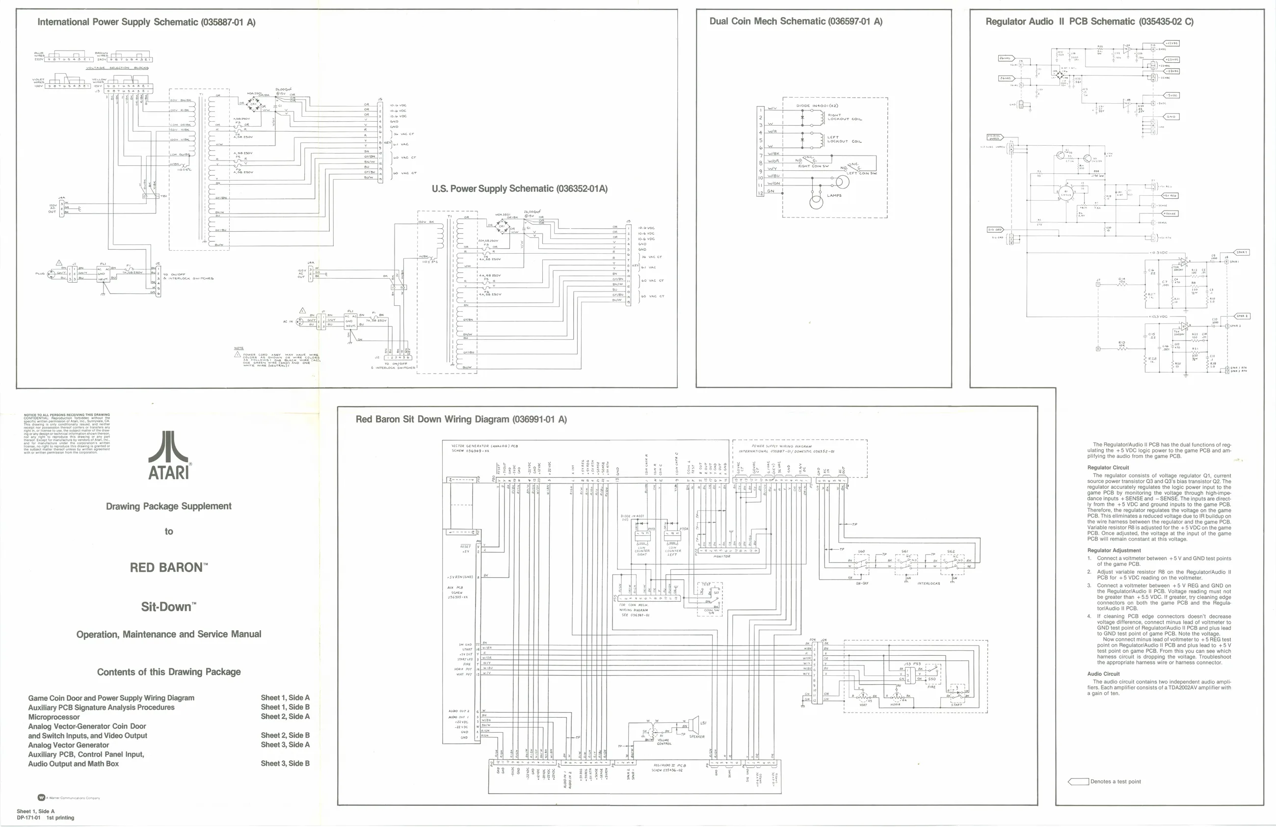
Regulator Circuit The regulator consists of voltage regulator Qt, current source power transistor Q3 and Q3's bias transistor G2. The regulator accurately regulates the logic power input to the game PCB by monitoring the voltage through highimpedance inputs + SENSE and ~ SENSE. The inputs are direct. ly from the +5 VDC and ground inputs to the game PCB. Therefore, the regulator regulates the voltage on the game PCB. This eliminates a reduced voltage due to IR buildup on the wire hamess between the regulator and the game PCB. Variable esistor R6 is adjusted for the +5 VDC on the game PCB. Once adjusted, the voltage at the input of the game lator/Audio ll PCB has the dual functions of reg- VDC logic power to the game PCB and am: uudio from the game PCB,
PCB will remain constant at this voltage.
Rogulator Adjustment
- Connect a voltmeter between +5 V and GND test points of the game PCB.
- Adjust variable resistor RB on the Regulator/Audio II PCB for +5 VDC reading on the voltmeter.
- Connect a voltmeter between +5 V REG and GND on the Regulator/Audio I PCB. Voltage reading must not bbe greater than +5.5 VOC. If greater, try cleaning edge Connectors on both the game PCB and the Regula: tor/Audio Il PCB. If cleaning PCB edge connectors doesn't decrease voltage difference, connect minus lead of voltmeter to GND test point of Regulator/Audio Il PCB and plus lead to GND test point of game PCB. Note the voltage. 'Now connect minus lead of voltmeter to +5 REG test ppoint on Regulator/Augio l PCB and plus lead to +5 V test point on game PCB. From this you can see which hhamess circult is dropping the voltage. Troubleshoot the appropriate harness wire or hares connector.
‘Audio Cireult The audio circuit contains two independent audio amplifiers. Each amplifier consists of a TDAZOQZAV amplifier with a gain of ten,
| << oenates a test point