Lunar Lander DP-136-3rd-01B
Lunar Lander (rev 2) (Atari, 1979) · Drawing Package · 1 pages · original scan
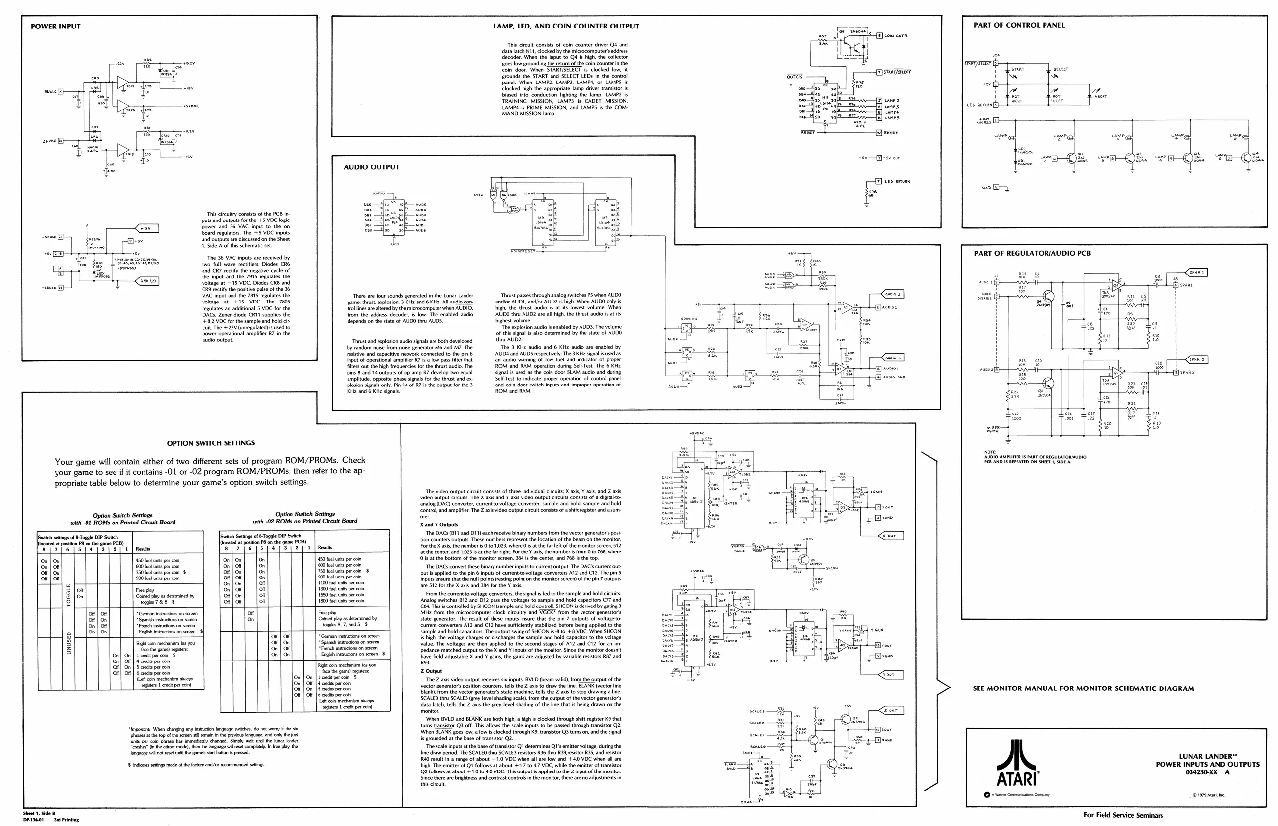
POWER INPUT
Fore ce Oe We EP
This circuitry consists of the PCB inputs and outputs for the +5 VDC logic power and 36 VAC input to the on board regulators. The +5 VDC inputs and outputs are discussed on the Sheet 1, Side A of this schematic set. The 36 VAC inputs are received by LAMP, LED, AND COIN COUNTER OUTPUT
This circuit consists of coin counter driver Q4 and. ‘data latch N11, clocked by the microcomputer’ address decoder. When the input to Q4 is high, the collector g0es low grounding the return ofthe coin counter in the coin door. When STARTSELECT is clocked low, it
AUDIO OUTPUT frounds the START and SELECT LEDs in the control Ecad panel. When LAMP2, LAMP3, LAMPS, or LAMPS is my clocked high the appropriate iamp driver transistor is biased into conduction lighting the lamp. LAMP? is TRAINING MISSION, LAMP3 is CADET MISSION, Z] wane 2 sare LAMPS is PRIME MISSION, and LAMPS is the COM: i] canes MAND MISSION lamp. fe] wanes fe] canes
sv —a)+sv oor
Leo nero
a PART OF CONTROL PANEL
‘| PART OF REGULATORIAUDIO PCB |
| : | Pee | ‘wo full wave rectifiers. Diodes CR6 | seg | ge | |||
| on | . | ‘and CR7 rectify the negative cycle of | . | _ | |||
| io) | the input and the 7313 repulates the | nett | oo | ¢ | |||
| voltage at —15 VDC. Diodes CR8 and | ma. | a | woe + | ANA | |||
| VAC input and the 7815 regulates the | There are four sounds generated in the Lunar Lander | Thrust pases through analog switches PS when AUDO | bp | ~n—E | i | ||
| voltage at | +15 VDC. | The 7805 | ‘game: thrust, explosion, 3 KHz and 6 KHz. All audio com | andor AUDI, andor AUD? is high. When AUDO only i, | * | a | : |
| regulates an additonal 5 VDC forthe | frollines ae seedy themicrocomputerwhen MUDIG. | igh, the thst ado i at Ks lowest volume. When | = | Soe] | 7Su | ' | |
| DACs. Zener diode CRN supplies the | from the odes deoder | low The enabled audio | AUD tr AUD ave al high the us uit | i | aa | H | |
| $102 VDC forthe sample and old ei | dlpends onthe tate of AUDO thru AUDS. | Wighest volume | % | H | |||
| uit The +22V onepuated i wsed to | “he explosion audio is enabled by AUD3.The volume | Pa | ' | ||||
| power operational amplifier R7 a the | of ths signal b also determined by the state of AUDD | cs | 8 | H | |||
| audio output. | ‘Thrust and explosion audio signals are both developed | thru AUD2. | H | ||||
| ty random nove fom nose generator Mand M7. The | The 3 KHz audio and 6 Kliz audio are enabled by | H | |||||
| tebe and capactivenework connected tothe pn'@-—-AUDtand AUDS respectively The 3K sgl sued ot | ‘ | H | |||||
| = | input of operational amplifier R7 isa low pass filter that | ‘an audio waming of low fuel and indicator of proper | a | me | ss | Lerma | |
| filters out the high frequencies for the thrust audio. The | ROM and RAM operation duting Self-Test. The 6 KHz | al | ag | ae | TF | ||
| bins 8 and 14 outputs of op amp R7 develop two equal | signal is used as the coin door SLAM audio and during | ae | a3 | Tt | aS | ti) sean 2 | |
| amplitude, opposite phase signals for the thrust and ex: | Self-Test to indicate proper operation of control panel | We | wie | 83 | = | ||
| plosion signals ony. in 14 of | isthe output forthe 9 | and com door switch Inputs and inproper operation of | Biel | ar | cu | ||
| KHz and 6 KHz signals, | ROM and RAM. | Aas | ge | cnac | tt |
OPTION SWITCH SETTINGS I Your game will contain either of two different sets of program ROM/PROMs. Check ADORE MUTED IS PARE GF REGULAZORIAUDAO) your game to see if it contains -01 or -02 program ROM/PROMs; then refer to the appropriate table below to determine your game’s option switch settings.
Snag (DAC) comer, eurenttovoltge Converter sample and bal, sample and hold
| Option Switch Settings | Option Switch Settings | peas | pier. | The | on | [ | |||
| with -01 ROMs on Printed Circuit Board | with -02 ROMs on Printed Circuit Board | X and ¥ Outputs | |||||||
| [bench | acing of Toso DP Such | wich Sein of 6 Tonge DIP Such | "he DAC(01 ad Bech ci Binary mbes om he ec ors os | ||||||
| ming | Bon DW | Sth | sch Senos of ome IP | Sut | tion courts | outputs. These nue Fepresert the location of the beam on the moor | |||
| SUT pers | Te | Ley 2 | 2 | Rese | err | yere | ye] | e | ted} | eae | Forte X an, the numbers | Oto 1.029 where Os athe fret ofthe montor sree, 512 |
the center and 1023 a the aright Forth Vx the umes ro to 8 where
| on | on | 150 aus prin | onfon] | [om | 0 fl wt pe om | sat the bottom of the monitor screen, 30s he center and 768i the top. | ||
| On| | of | {20 fod us prin | onl | or| | fon | 0 fl apron | The DACS convert these binary number inputs to curent output. The DAC cure out |
| Of | On. | 750 fuel units per coin $ | Off | On. | On | ‘750 fuel units per coin $ | put is applied to the pin 6 inputs of current-to-voltage converters A12 and C12. The pin 5 | ||
| oH | on | 900 fa unt er on | or} | ot | | |.on | ed epee | inputs ensure tha he rl pons esting point on the monitor screen) of the pn 7 outputs | |
| a | ‘On| | On | on | ber tri | are 512 for the X axis and 384 for the Y axis. | ||
| Sor | Fe py | onl | or] | Jor | 10 unis pr eon | ||
| Blo | Ganed py 2s termine by | oon] | Joe | 180 fo use pr nn | From the curenttoveltge converters, the signals fed othe sample and hold cits | ||
| 8 | waerae § | oefor] | [oe | 10 fo wt pr ln | Analog sutces 812 and OY2 pass the voltages to sample and bold capacitors C77 and |
e Cat Ths conoled by sCONtample an hold conta SHICON is deve y sain >
| al | te | “Geman tucson oe | oF | Fee | Miz from the microcomputer clock ceutry and WOCR® from the vector gonerators | |
| Ot | | “Spahr onsen | & | Caned py as tern by | Sate genrator. The reo ofthese Inputs ure thatthe pi 7 cuts of wage | L | |
| On| | oF | “Rech wus on ser | perry | Current converters AZ and C12 have sufclenly stablized before berg applied tothe | ||
| a] | foofon | Edhar onsen § | - | Sample and hold capacitors. The output sving of SHCON sto. +8 VDC When SHCON | ||
| 2 | of | oF | ‘Geman inrucons on sreen | is high, the voltage charges or discharges the sample and hold capacitor to the voltage | |||
| 3 | Right coin mechani (as you | 0 | On | {Spanih isructons on sen | value. The voltages are then applied to the second stages of A12 and C12 for an im- | ||
| 5 | Da Speaoe mar aa | Lod | I) | fact pentane | sao) | pedance matched output to the X and Y inputs of the monitor. Since the monitor doesn't |
| On| | On| | 1 credit per coin $ | On | On | cel sab | arate | hhave field adjustable X and Y gains, the gains are adjusted by variable resistors R87 and |
| On| | ot | dant prea | io | ||||
| 4] | On | Seedy pe con | Tia con meron a 0 | ||||
| Ot | Of | Gaede percon | tet gu) ise | Z output | |||
| (Left coin chan cays | en m | Hpies ated s | ‘The Z axis video output receives six inputs. BVLD (beam valid), from the output of the | |||
| registers | Per | poeree | abet | ‘vector generator’ position counters, tells the Z axis to draw the line. BLANK (vector line | ||
| | | On| | Son | cn | blank fom the vector generators state machine tls the Z axis to stop drawing a ne | SEE MONITOR MANUAL FOR MONITOR SCHEMATIC DIAGRAM |
{Lat coin mechani aloays 'SCALEO thru SCALE3 (grey level shading scale), from the output of the vector generator’s
| Bey | death tl the | te ey tel Shing ot tne tg tone |
‘When BVLD and BTARR ar both igh, high clocked through shit register KO that a . tums tansstor QB off This allows the scale put to be pased through Wansstor
| npomme Vite ing any | con langinge she, do nt ony | vans | = |
| iesss othe Gps te easy cin He | jovi Meguage, Ad cay fa fo | When BLANK goes low, a low is clocked through K9, transistor Q3 turns on, and the signal | oh |
| tras per con as astray cng, Sng ok | ar ar | ‘sounded a the base of tansstor 2. | ail |
| ‘Tater (bans model ten engage let comp. | fe ly, the | The scale inputs atthe base of transistor QI determines Q's emir voltage, during the |
‘Sos note ult ue at a ree, line daw prod The SCALEO thy SCALES restr: R36 th 9 resstor RS, and esto [R40 result in a range of about +1.0 VDC when all are low and +40 VDC when all are LUNAR LANDER™
| '$ indicates settings made at the factory and/or recommended settings. | high. The emitter of Q1 follows at about +1,7 to 4.7 VDC, while the emitter of transistor | POWER INPUTS AND OUTPUTS |
QB olows st aboot +10 to.40 VOC. Ths output applied tothe Z input of the monitor , past Since there ae bighines and contrast controls nthe monitor, thee are no adjustment ATARI mx A this circuit. ZZ © bnew concn ony 107 a For Field Service Seminars DPA3601 3rd Printing