Asteroids Deluxe DP-165-3rd-01B
Asteroids Deluxe (rev 3) (Atari, 1980) · Drawing Package · 1 pages · original scan
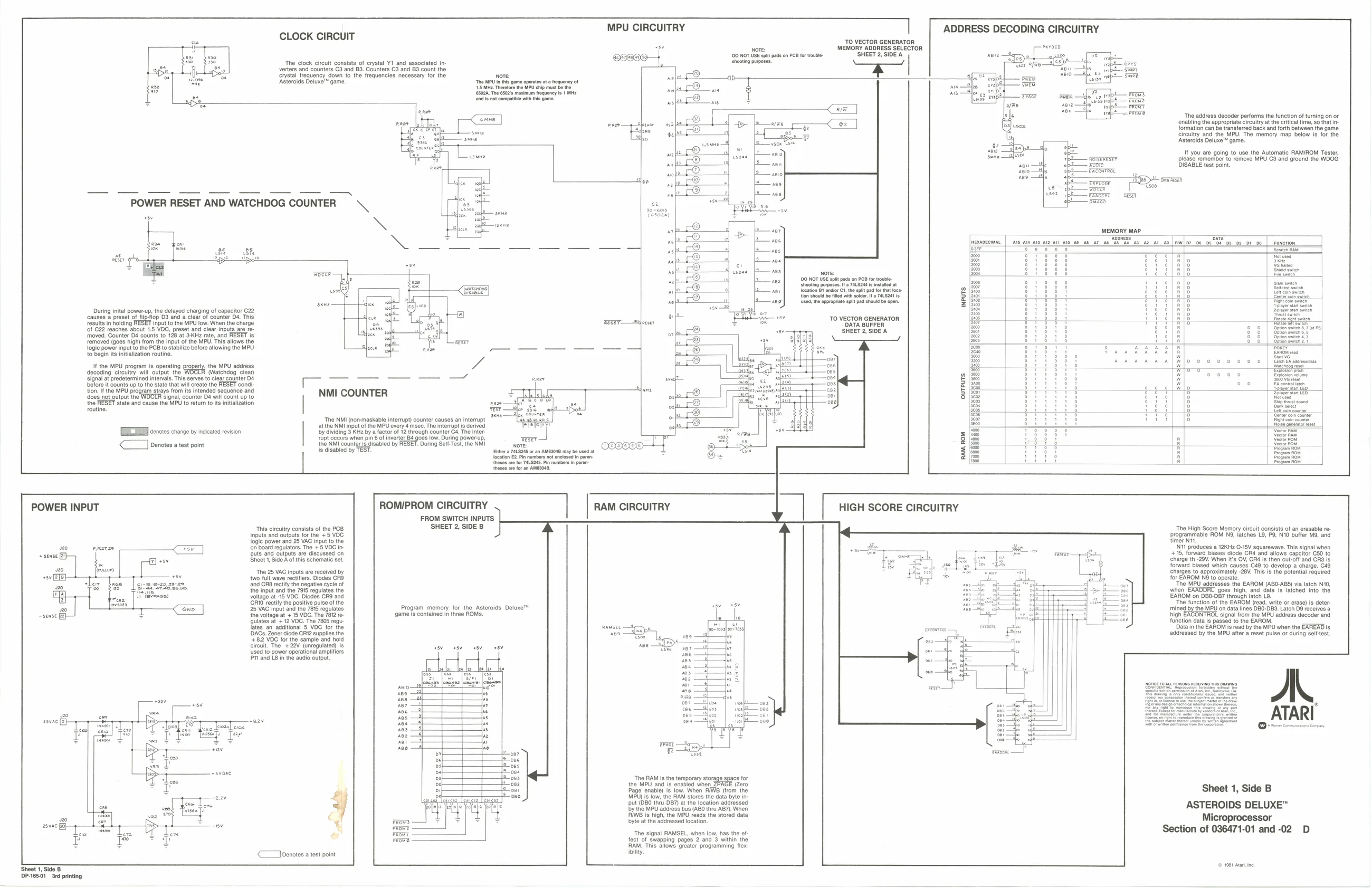
CLOCK CIRCUIT
The clock circuit consists of crystal Y1_and associated in-
verters and counters C3 and B3. Counters C3 and 83 count the
crystal frequency down to the frequencies necessary for the ‘Asteroids Deluxe" game, The {SH Thraore the MPU chip mu Nore: PU in this game operate at equency of be the (5028. The 6502s maxim Woquency fe} MME
of sone not compte wih ths game
Bh.
MPU CIRCUITRY
Nore:
shooting purposes. 120 NOT USE spit pads on PCB for trouble TO VECTOR GENERATOR (MEMORY ADDRESS SELECTOR ‘SHEET 2, SIDE A a a
ADDRESS DECODING CIRCUITRY
aime ea
{2 — anne to
(e368) ;
During inital power-up, the delayed charging of capacitor C22 ‘causes a preset of fliptiop D3 and a clear of counter D4. This
FRESET input tothe MPU tow. When the charge
5 VOC, preset and clear inputs are removed. Counter D4 counts to 128 at 3KH2 rate, and RESET is removed (goes high) from the input of the MPU. This allows the
lowing the MPU
results in holding (of C22 reaches about
logic power input to the PCB to stabilize before 10 begin its initialization routine.
If the MPU program is operating decoding circuitry will output the ‘signal at predetermined intervals. This serv
the routine,
TEI cerctes crane by nsicate revision
< Denotes a test point sy, the MPU adress (Watehdog cia clear goantr Dt Betre aunts up toe sata hat il rata no RESET con ton. the MPU progam stays om its intended sequence an {docs not output the WOCTR signal, counter b4 wil count up to ‘State and cause the MPU To return to ntaizaion Cirired
NMI COUNTER
‘The NMI (aonmaskable interrupt) counter causes an interrupt atthe NMI input of the MPU every 4 msec. The interrupt is derived by dividing 3 KH2 by a factor of 12 through counter C4, The inter: ‘pl gece when pn of invert Ba gos iow. During power up, the NMI counter Ig disabled by uring Self-Test, the NMI Is disablod by TEST. hor 74.5285 or an AMBSOEB may bo ute a location E2 Pin number not enclosed in pre theses no for 74LS2. Pn numbers in pron esos ar or an AMESONB. Reece ee
Nore 100 NOT USE spit pads on PCB fr trouble: Shooting purposes a 785244 i intl a location Bt andlor Ci, he spit pad or hat lee. tion shoud be fed with soir PaL.S249 fe ‘used the appropriate spit pad should be ope.
TO VECTOR GENERATOR DATA BUFFER SHEET 2, SIDE A
bau eae
rues ses, es isi al
ooseao—l}
POWER INPUT
sense
-seuse i
osvone
‘Sheet 1, Side B P6501 Sed printing ROMIPROM CIRCUITRY
This circuitry consists of the PCB SHEET 2, SIDE B Inputs and outputs for the +5 VDC logic power and 25 VAC input to the (on board regulators. The +5 VDC inputs and outputs are discussed on Sheet 1, Side A of this schematic set “The 25 VAC inputs are received by two full wave rectifiers. Diodes CRO ‘and CR8 rectly the negative cycle of the input and the 7916 regulates the voltage at -15 VOC. Diodes CR9 and CRO rectify the positive pulse of the 25 VAC input and the 7815 regulates the voltage at + 15 VOC. The 7812 reulates at + 12 VDC. The 7805 regu lates an additional § VOC. for DACs. Zener diode CRt2 supplies +82 VDC for the sample and hold circuit. The +22V (unregulated) is Used to power operational amplifiers Pt and LB in the audio output ‘contained in three ROMs. ams FROM SWITCH INPUTS
Program memory for the Asteroids Deluxe™
aez — faz
cay
Dee
<Joenotes a test point RAM CIRCUITRY
‘The RAM is the temporary storage space for the MPU and is enabled when. (Zero Page enable) is low. When RAB (from the MPU) is low, the RAM stores the data byte in put (DBO thru DB7) at the location addressed by the MPU adaress bus (ABO thru AB7). When IB is high, the MPU reads the stored data byte at the addressed location.
‘The signal RAMSEL, when low, has the of: fect of swapping pages 2 and 3 within the RAM. This allows greater programming flex ‘bility
| t26 * aysph | Pare | asst wap |
Is |e Ls saab ‘The address decoder performs the function of turning on or formation can be transferred back and forth between the game circuitry and the MPU. The memory map below is for the ‘Asteroids Deluxe™ game.
P 4 If you are going to use the Automatic RAM/ROM Tester, : cues taal ane MUS and gow he WOO sou—2e BiSsbc ea pt
sps— exrcoor ay us > abe wen sez be ‘ERROTPL RESET
smn map
| ze | 07 | t | ee |
| = | pidi | mH | Tow |
ie Pitt art oe | Seeened
iis : ae
HIGH SCORE CIRCUITRY
rece —y ‘The High Score Memory crcult consists ofan erasable eprogrammable ROM Niches 18, P, NiO bute Mond timer Nit Nit produces a 12KHz 045V squarewave. This signal when +15, forward biases ode CR& and allows capctor C30 to charge th-20V. When i's Ov, ORE fs then cual and GRO is forward biased which causes C49 to develop a charge. C48 Charges to approximately “26V, Tiss the potent reauted for EAROM NO to operte “The MPU addresses the EAROM (AB0-ABS) via latch N1O, wen goes igh, and data ie latched Into the EAROM on DB0-DB7 trough atch L2. “he function of the EAROM (ead, write or eras) is deter mined bythe MBU on data ines DBO-DBS. Latch BO veces high EACONTROL signal from the MPU addross docoder and function data ie pasea tothe EAROM. Data inthe EAROM is read bythe MPU when the ERRERD is creased by the MPU after a reset pulse or dung suttest.
AL ATARI
Sheet 1, Side B
ASTEROIDS DELUXE™ Microprocessor Section of 036471-01 and -02 D
© 1981 Ata, te