Lunar Lander DP-136-1st-02B
Lunar Lander (rev 2) (Atari, 1979) · Drawing Package · 1 pages · original scan
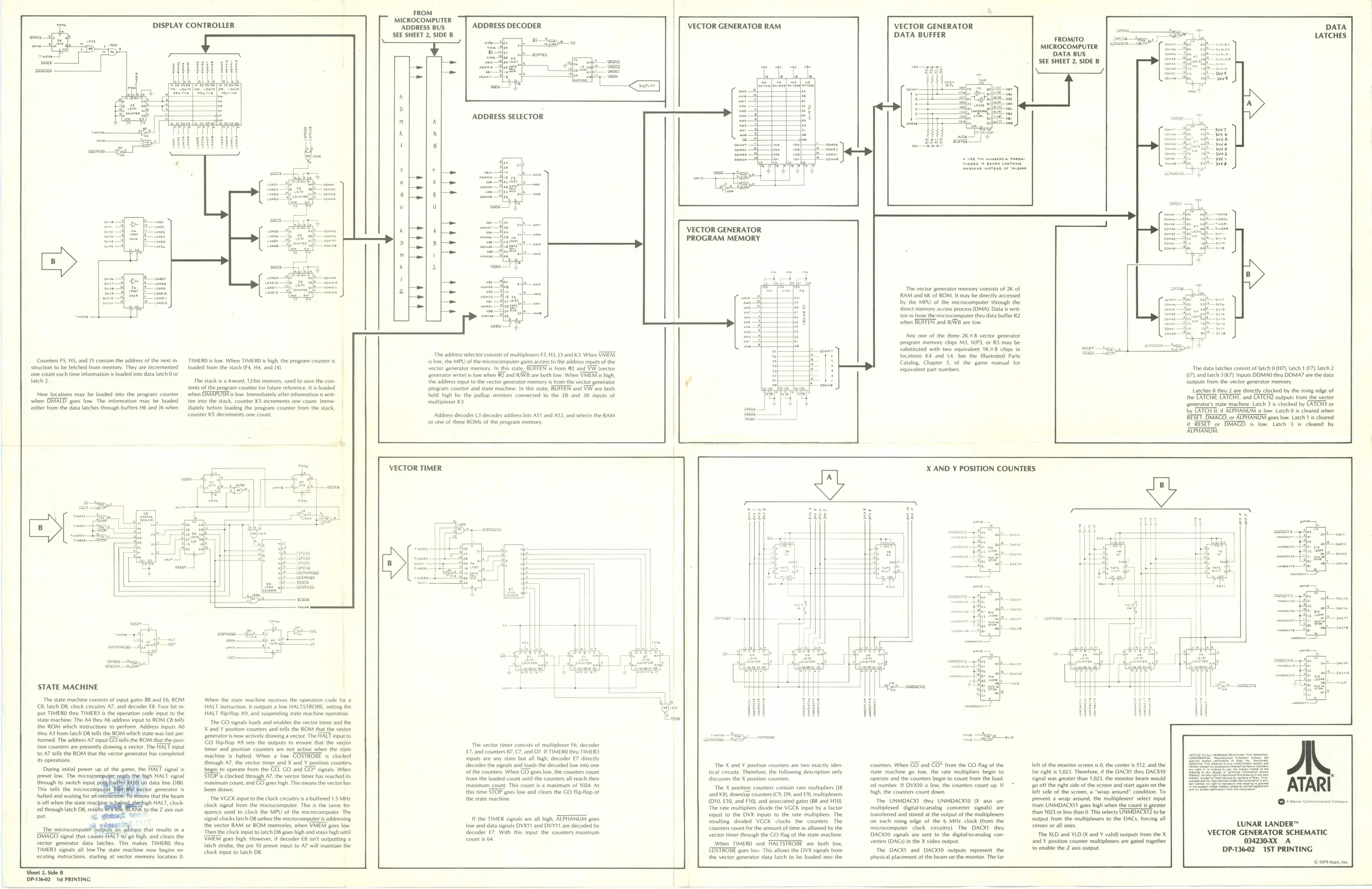
MICROCOMPUTER DISPLAY CONTROLLER ‘ADDRESS BUS. ADDRESS DECODER [Vector GENERATOR RAM VECTOR GENERATOR ET 2, SIDE B ‘SEE SHEE sl — = DATA BUFFER FROMITO. [Slee cae } = MICROCOMPUTER DATA BUS
id SEE SHEET 2, SIDE B
A
> ' i ADDRESS SELECTOR
q Lh t 6
am. - The bhi 3 — : " whe = Ce ee re
¥ v
‘small &
> 5
wn Lela B 4 2
‘owe i Jom = ate ‘i ‘The vector generator memory consists of 2K of me RAM and 6K of ROM. Itmay be directly acessed nan oo by the MPU of the microcomputer though the ne ee dlrect memory access process (OMA) Data writ met ae ten in from the microcomputer thru data buffer R2 when BUFFER’ and RAWB are low
‘Any one of the thee 248 vector generator program memory chips M3, NIP3, of R3 may be
- Substituted with two equivalent 1KX8 chips in The adres selector consists of multinlexersF, M3, and K3, When VETER, locations K4 and La. See the Mlustated Parts Counters F5, 15, and J5 contain the address ofthe next ir TIMEROD i low. When TIMERD i high, the program counters ‘slow, the MPU ofthe microcomputer gins access to the addres inputs of the Catalog, Chapter 5, of the game manual for struction to be fetched from memory. They ate incremented loaded from the stack (F4, H4, and 4) ‘vector generator memory. In ths sat BUFFEN i from @2 and WW (vector equivalent part numbers “The data latches consist of latch 0 (H7), latch 1 (F7), latch 2 ‘one count each time information is loaded into data latch 0 or _generator write) is low when $2 and RWB are both low. When VMEM ts high, U7), and latch 3 (K7). Inputs DDMA0 thru DDMA7 are the data Tatch 2. The stacks a 4ord, 72 memory used to save the con- the adress input tothe vector generator memory from the vector generator ‘outputs from the vector generator memoy. tents of the program counter for future reference. It is loaded ‘program counter and state machine. In this state, BUFFEN and VW are both Latches 0 thru 2 are directly clocked by the risi of New locations may be loaded into the program counter when OMAPUSH is low. Immediately after information is writ- ‘held high by the pullup resistors connected to the 2B and 38 inputs of the TATCHO, LATCHT, and aren pale tontaeae when DMATD goes low. The information may be loaded ten into the stack, counter KS increments one count. Imme- multiplexer K3, ‘generator’s state machine. Latch 3 is clocked by TATCHS or [ther from the data latches tough butfers H6 and J when ately before loading the program counter Irom the stack, by LATCH, ALPHANUM slow. Latch 0s cleared when “counter K5 decrements one count. Address decoder L3 decodes address bits A11 and A12, and selects the RAM. RESET. DMAGO, or ALPHANUM goes low. Latch 1 is cleared or one of tree ROMS of the program memory RESET or DMACO low. Latch 3. cleared. by ‘APHANUM
VECTOR TIMER:
STATE MACHINE
The state machine consist of input gates BB and £6, ROM 8, latch DB, clock circuitry AT, and decoder EB. Fout bit i> ‘put TIMERO thru TIMER3 isthe operation code input to the ‘ate machine. The Ad thru A6 addres input to ROM CB tells the ROM which instructions to perform. Address inputs AO {tr A3 from latch D8 tells the ROM which state was last pee formed. The address A7 input GO tells the ROM thatthe post
tion counters are presently drawing a vector. The HALT input
to A7 tells the ROM thatthe vector generator has completed is operations Dring inital power up of the game, the ALT signal is preset low. The microcomp ‘the high HALT signal through its switch input fn data line DBO. This tells the. microcompy tor generators halted and waiting for ani are thatthe beam is off wen te sate maching aaah HAL, lock ed through latch 08, results to the Z axis out put. m genee or The microcomputePoutpulean adress that rests in a BMAGO signal that causes HALT to go high, and clears the vector genrtor data latches, Thi makes TIMER TIMERS sls fow:The sts mochie tow begee or teutngnsuctons sarng at vector memory beaten 0. When the state machine receives the operation code for a HALT instruction it outputs alow HALTSTROBE, setting the HALT flipflop AS, and suspending state machine operation ‘The GO signals loads and enables the vector timer and the X and Y position counters ad tells the ROM thatthe vector
sgenerators now actively drawing a vector. The HALT input to through A7, the vector timer and X and Y position counters
Go fliptlop 9 sets the outputs to ensure that the vector timer and positon counters are not active when the state machine is halted. When 2 low GOSTROBE is clocked
begin to operate from the GO, GO and GO* signals. When
STOP'is clocked through A7, the vector timer has reached its
‘maximum count, and GO goes high. This means the vector has
been drawn The VGCK input tothe clock circuitry is a buffered 15 MHz clock signal from the microcomputer. This isthe same fre ‘quency used to clock the MPU of the microcomputer. The signal clocks latch D8 unless the microcomputer is addressing the vector RAM or ROM memories, when VMEM goes low. “Then the clock input to latch D8 goes high and stays high until \VMEM goes high. However, if decoder E8 isn't outputting 2 latch strobe, the pin 10 preset input to A7 will maintain the clock input to latch D8. FROM
The vector timer consists of multiplexer F6, decoder 7, and counters B7, C7, and D7. IF TIMERO they TIMERS, inputs are any state but all high, decoder €7 directly decodes the signals and loads the decoded low into one ‘of the counters. When GO goes low, the counters count ‘rom the loaded count until the counters all reach their maximum count. Tis count isa maximum of 1024. At this time STOP goes low and clears the GO flipflop of the state machine
If the TIMER signals are all high, ALPHANUM goes low and data signals DVXT1 and DVY11 are decoded by decoder £7. With this input the counters maximum count i 64 The X and ¥ position counters are two exactly iden tical circuits. Therefore, the following description only ‘discusses the X position counters, The X position counters contain rate multipliers (18 and K8), down/up counters (C9, D8, and £9), multiplexers (O10, 10, and F10), and associated gates (B8 and H10) ‘The rate multipliers divide the VGCK input by a factor equal to the DVX inputs to the rate multiplies. The resulting divided VGCK clocks the counters. The Counters count forthe amount of time as allowed by the vector timer through the GO flag of the state machine When TIMERO and HALTSTROBE are both low, EDSTROBE goes fo. This allows the OVX signals from the vector generator data latch to be loaded into the X AND Y POSITION COUNTERS
counters, When GO and GO* from the GO flag of the state machine go low, the rate multipliers begin to ‘operate and the counters begin to count from the load: ‘ed number. If DVK10 is low, the counters count up. If high the counters count down, The UNMDACXT they UNMDACKTO 0 axis unmultiplexed. digitaltoanalog converter signals) are transferred and stored at the output of the multiplexers ‘on each rising edge of the 6 MHz clock (from the microcomputer clock citcuity). The DACKT the DACX1O signals are sent to the digitalto-analog converters (DACS) in the X video output The DACKI and DACXTO outputs represent the physical placement ofthe beam on the monitor. The far left of the monitor screen i 0, the centr is $12, and the far right is 1023. Therefore, ifthe DACX1 thru DACKIO signal was greater than 1,023, the monitor beam would {0 off the right sie ofthe screen and start again on the left side ofthe screen, a “wrap around’ condition. To prevent a wrap around, the multiplexes’ select input from UNMDACX11 goes high when the count is greater than 1023 ores than OT selects UNMIDNORT to be ‘output from the multiplexers to the DACS, forcing all 2er0es or all ones The XLO and YLD (K and ¥ valid) outputs from the X and Y position counter multiplexers are gated together to enable the Z axis output + vere comma Comciny
LUNAR LANDER™ VECTOR GENERATOR SCHEMATIC 034230-XX_ A. DP-136-02 1ST PRINTING |i ean Sheet 2, Side 8 DP-13602 Ist PRINTING
- i |