Asteroids Deluxe DP-165-3rd-02B
Asteroids Deluxe (rev 3) (Atari, 1980) · Drawing Package · 1 pages · original scan
INPUTS OUTPUTS
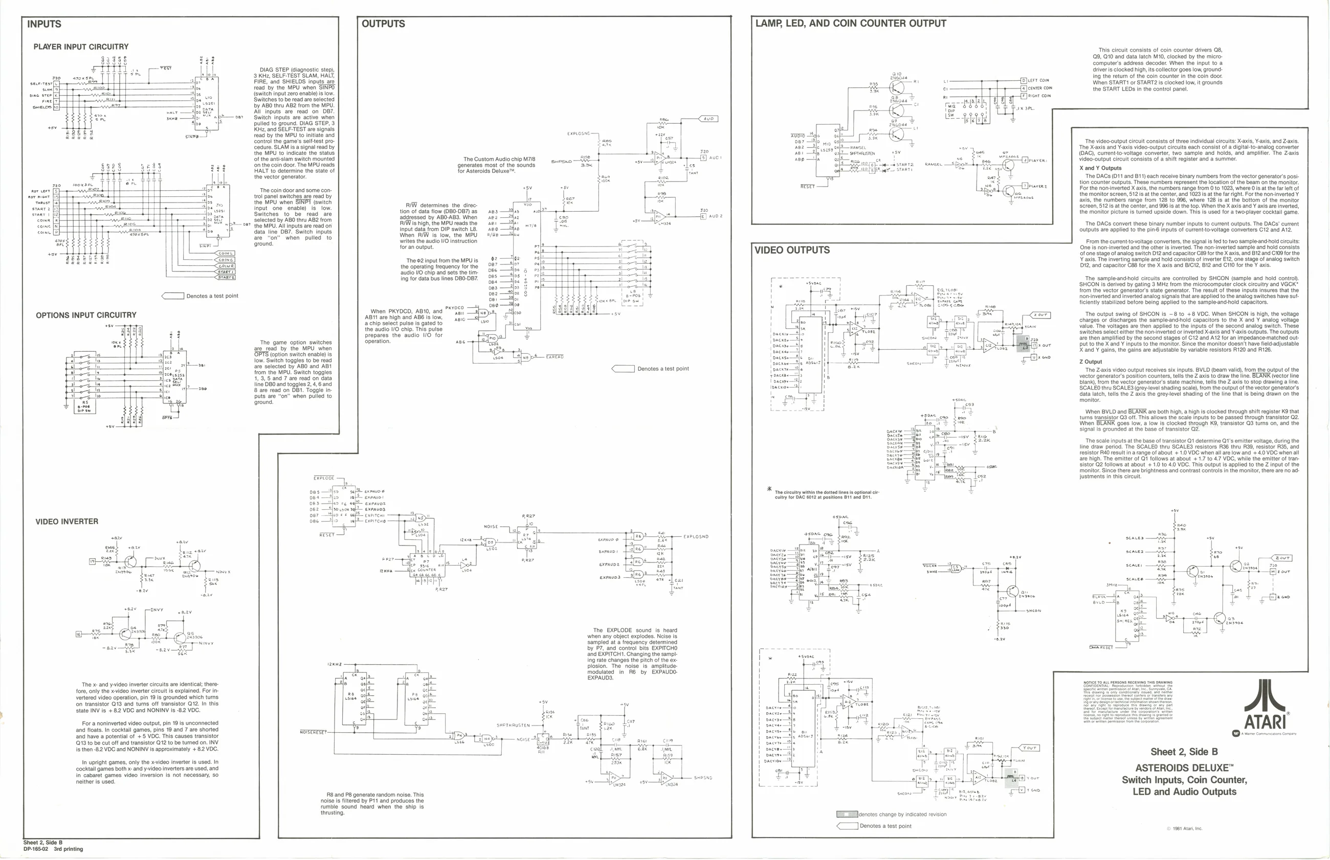
PLAYER INPUT CIRCUITRY
Passel DIAG STEP (diagnostic step),
ne soasee |] ‘3. KHz, SELF-TEST SLAM, HALT,
| seceresr[e) | soe | FIRE, ‘and SHIELDS inputs are |
Semel I read ‘by the MPU when SINPO. pine sree {switch input zero enable) is low.
pone — ‘Switches to be read are selected
‘suocs fo) — bby ABO thru AB2 from the MPU. All inputs are read on O87. nbt—oe Switch inputs are active when
pulled to ground. DIAG STEP, 3
kHz, and SELF-TEST are signals Cedure, SLAM isa signal read by
read by the MPU to initiate and control the game's selttest pro-
the MPU to indicate the status of the anti-siam switch mounted
for an output.
When PKYDCD, ABI0, and {AB1t are high and ABE is low,
‘a chip select pulse is gated to
the audio 1/0 chip. This pulse prepares the audio 1/0 for ‘The game option switches operation, are ead by the MPU when ‘OPTS (option switch enable) is low. Switch toggles to be read are selected by ABO and ABI from the MPU. Switch toggles 1, 3, and 7 are read on data line 080 and toggles 2, 4, 6 and 8 are read on DBI. Toggle inbuts are “on” when pulled to ‘groun
oarroe
oes — 064 425
2 exravo3,
VIDEO INVERTER
‘The x- and y-video inverter circuits are identical; there: fore, only the xvideo inverter circuit Is explained. For in vertered video operation, pin 19 is grounded which tus fn transistor Q13 and turns off transistor Q12. In this state INV is +82 VOC and NONINV is -82 VDC.
For a noninverted video output, pin 19 is unconnected and floats. In cocktall games, pins 19 and 7 are shorted
| ‘The? input rom the | MPUis | 8 | —Z18? |
the operating frequency for the = ‘audio VO chip and sets the timing for data bus lines OB0-DB7. ‘The Custom Audio chip M78, exevosne:
| e528 | gedd | ‘on the coin door. The MPU reads | generates most of the sounds | =P | S5 |
| S253 | Sous | HALT to determine the state of | for Aster | Deluxe™. |
F1Iilil,, iif the vector generator. mo twooxsee | ii a on
| et | + | The coin door and some con- | i | ma | ||
| deat | creat | trol panel switches are read by | 5 | her | ||
| rice | vont | the MU when SINT (ach | IW doting tno dee | <a | bi | |
| saan [r | t | frou one enable) | 18, | le | tion of data flow (O80:DB7) as | no |
| sane | [| | t | t | Buliches,t6 | hes ceed at | ‘addressed by ABO-AB3. When | eS |
| oxi | oer | t | faut stom DI och U8 | |||
| pared | a | satin ar sate ae | Input | ai rom I | oe |
are “on” when pulled to wes the audio 10 instruction ‘ground. .
| 87 | —t{>r | ee |
66 —Hoe 5 00s —4hos ¢ bee —oe 3
| bes | —}os | ae |
bee Hoag
te
swernmusren —4
‘and have a potential of +5 VOC. This causes transistor <7 penotes a est point
exPLOsNO
‘The EXPLODE sound is heard when any object explodes. Ncise Is sampled at a frequency determined by P7, and control bits EXPITCHO and EXPITCH1. Changing the sampling rate changes the pitch of the explosion. The noise is amplitude: Modulated in R6 by EXPAUDO- EXPAUDS.
13 to be cut off and transistor G12 to be turned on. INV Is then -82 VDC and NONINV is approximately + 8.2 VOC.
In upright games, only the x-video inverter is used. In cocktail games both x-and y-video inverters are used, and in cabaret games video inversion is not necessary, 50 neither is used.
‘RB and P8 generate random noise. This noise is filtered by P11 and produces the rumble sound heard when the ship is thrusting, Lhe cue wh]_Ss7 LAMP, LED, AND COIN COUNTER OUTPUT
Burr com
UB Ad. cen com
VIDEO OUTPUTS
“The culty witia the dotted tn {uly for ORG 6012 postions 81 ana BY
fe Fs et
aod he alt
[Woorotes change by indicated revision << Jpenotes a test point
‘Sheet 2, Side B 1DP-165-02 rd printing ‘This circuit consists of coin counter drivers 08, (09, Q10 and data latch M10, clocked by the micro computer's address decoder. When the input to a drivers clocked high, its collector goes low, ground ing the return of the coin counter in the coin door. When START! of START2 is clocked low, it rounds the START LEDs in the control panel.
The video-output circuit consists of three individual circuits: X ‘The X-axis and Y-axis video: output circuits each consist ofa digital-to-analog converter (OAC), curentio-voltage converter, two sample and holds, and amy Video-output circuit consists of a shift register and a summer. X and Y Outputs ‘The DACs (011 and B11) each receive binary numbers from the vector generator's position counter outputs. These numbers represent the location of the beam on the monitor. For the nom-inverted X axis, the numbers range from 0 to 1023, where Os at the far eft of the monitor screen, $12 atthe center, and 1023 is atthe far right. For the non-inverted Y axis, the numbers range from 128 to 996, where 128 is at the bottom of the monitor Screen, 612s at the center, and 996 is atthe top. When the X axis and Y axis are inverted, the monitor picture is tured upside down. This is used for a two-player cocktail gam:
‘The DACs convert these binary number inputs to current outputs. The DAGs' current outputs are applied to the pin inputs of currenttovoltage converters C12 and A12, From the current-tovoltage converters, the signal fed to two sampleand-hold circuits: (ne is non-inverted and the other is inverted. The non- inverted sample and hold consists of one stage of analog switch D12 and capacitor C89 forthe X axis, and B12 and C109 forthe Y axis. The inverting sample and hold consists of inverter E12, one stage of analog switch 12, and capacitor C88 for the X axis and BICI2, B12 and C110 forthe Y axis.
The sample-and-hold circuits are controlled by SHCON (sample and hold contro), ‘SHCON is derived by gating 3 MHz from the microcomputer clock circuitry and VGCK" from the vector generator's state generator. The result of these inputs insures that the nominverted and inverted analog signals that are applied tothe analog switches have su ficiently stabilized before being applied to the sample-and-hold capacitors.
‘The output swing of SHCON is ~8 to +8 VOC. When SHON is high, the voltage charges or discharges the sampleand-hold capacitors to the X and Y analog voltage value. The voltages are then applied to the inputs of the second analog switch. These Switches select either the non-inverted or inverted Xaxis and Y-axis outputs. The outputs are then amplitied by the second stages of C12 and A12 for an impedance:matched output to the X and ¥ inputs to the monitor. Since the monitor doesn't have field-adjustable X and ¥ gains, the gains are adjustable by variable resistors R120 and R126.
Z Output ‘The Z-axis video output receives six inputs. BVLD (beam valid), from the output of the vector generator’s position counters, tells the Z axis to draw the line. BLANK (vector line blank, ftom the vector generator’s state machine, tells the Z axis to stop drawing a line. SCALEO thru SCALES (grey-level shading scale), from the output of the vector ganerator’s data latch, tells the Z axis the grey-level shading of the line that is being drawn on the ‘monitor. ‘When BVLD and BLANR are both high, ahigh is clocked through shift register K9 that tumns transistor Q3 off. This allows the scale inputs to be passed through transistor Q2. When ‘908s low, a low is clocked through K9, transistor Q3 turns on, and the signal is grounded at the base of transistor 2. ‘The scale inputs atthe base of transistor Q1 determine Q1's emitter voltage, during the line draw period. The SCALEO thru SCALES resistors R36 thru 39, resistor R35, and resistor RAO result in arange of about + 1.0 VDC when all are low and + 4.0 VOC when all are high, The emitter of Qi follows at about + 1.7 o 4.7 VDC, while the emitter of transistor @2 follows at about + 1.0 to 40 VOC. This output Is applied to the Z input of the ‘monitor. Since there are brightness and contrast controls in the monitor, there ae no adjustments in this circuit
Sheet 2, Side B ASTEROIDS DELUXE™ Switch Inputs, Coin Counter, LED and Audio Outputs