T2 Judgement Day (16-40009-101-1) Dec 1991
Terminator 2: Judgment Day (L-8) (Williams, 1991) · Manual · 74 pages · 41 sections · original scan
December 1991 16-40009-101-1
e MIDWAY
TM and © 1991 Carolco
TERMINATOR 2&2
@¢ JUDGMENT DAY
THE VIDEO
Operations Manual
- Game Operation & Adjustments
- Game Testing & Problem Diagnosis
- Parts Information
- Wiring Diagrams & Schematics
oad
TERMINATOR 2 Game Rules
You need two credits to start a game, and one credit to continue.
For a single player game press either of the Red, Player 1 Start Buttons after coins have been inserted. For a two player game, press either of the Red, Player 1 Start Buttons and, either of the Blue, Player 2 Start Buttons after coins have been inserted.
Press the trigger to shoot at targets. Press the Red Bomb Button on the gun to launch rockets. Pick-up “Power-ups” by shooting them.
Mission 1 In the future... Join up with Sgt. John Connor - leader of the Human Resistance - to destroy the Machines of Skynet. Infiltrate Skynet Headquarters to ultimately control the Time Field Generator.
Mission 2 In the present... Sent back through the Time Field Generator to protect young John Connor at all costs! Destroy Cyberdyne Systems to save the world from Judgment Day!
MIDWAY MANUFACTURING COMPANY RESERVES THE RIGHTS TO MAKE MODIFICATIONS AND IMPROVEMENTS TO ITS PRODUCTS.
THE SPECIFICATIONS AND PARTS IDENTIFIED IN THIS MANUAL ARE SUBJECT TO CHANGE WITHOUT NOTICE.
Terminator 2
TABLE OF CONTENTS Section 1 Operation and Troubleshooting
Set-up Procedure Installation & Inspection. Location Requirements... Front Cabinet Assembly Diagram. Rear Cabinet Assembly Diagram.
Game Features Starting-up... Player Controls. Control Panel Diagram. Game Operation Control Switches Control Switch Location Diagram Menu System Operation Hee bob Anko
eee
Operation.. + 1-10 Main Menu - 1-10 Diagnostic Tests. 1-11 Switch Test. 1-11 DIP Switch Test & Table. . 1-12 CPU & Sound Tests. 1-13 Monitor Patterns . 1-14 Burn-in Test 1-15 Coin Bookkeepin; 1-16 Game Audits...... 1-17 Game Adjustments. 1-19 Standard Pricing Tab! 1-22 Custom Pricing Table. 1-23 Utilities........ 1-24 Calibrate Gun: 1-25 Troubleshooting... 1-26
Section 2 Parts Information Cabinet, Speaker, Manuals, & Monitor... PC Boards, Transformer & Lamp Assy, Cables... Power Suppl: CPU Board... Sound Board. Coil Lamp Driver Boar Gun Assembly............. Dual Flashlamp & LED Boards
Section 3 Diagrams and Schematics CPU Board. Dual Flashlamp & LED Boards. Sound Board............ Coil Lamp Driver Boar JAMMA Chart & Power Wiring Diagram Cabinet Wiring & Main Harness Wiring Control Panel Wiring.
© Copyright 1991 MIDWAY Manufacturing Company
Terminator 2
SECTION one
Operation
Safety Notices
The following safety instructions apply to all game operators and service personnel. Specific warnings and cautions will be found throughout thismanual where they apply. We recommend that you read this page before preparing your game for play.
ZN CAUTION AC POWER CONNECTION, Before connecting the game to the AC power source, verify that the "line voltage selection chart" Jumper wires are installed correctly for the line voltage in your area. For details, refer to Section 3.
PROPERLY GROUND THEGAME. To avoid electrical shocks, do not plug in the game until it has been inspected and properly grounded. MIDWAY games should only be plugged into a grounded 3-wire outlet. Shocks will also result, if the control panel is not properly grounded! After servicing any parts on the panel, assure that the ground wires are secure. Only then should you lock up the game.
DISCONNECT POWER DURING REPAIRS. To avoid electrical shock, disconnect the game from the AC power source before removing or repairing any part of the game.
USE THE PROPER FUSE. To avoid electrical shock, use the replacement fuse which is specified in the parts list for this game. The replacement fuse must match the original fuse in fuse type, voltage rating, and current rating.
MONITOR PRECAUTIONS. When removing or repairing the monitor, extra precautions must be taken to avoid electrical shock because high voltages may exist within the monitor circuitry and cathode ray tube (CRT) even after power has been disconnected. Do not touch internal parts of the monitor with your hands or metal objects! Always discharge the CRT by the following method: Attach one end of a large, well-insulated, 20-kV jumper to ground. Momentarily touch the free end of the groundedjumper to the anode by sliding it under the anode cap. Wait two minutes and discharge the anode again,
HANDLE FLUORESCENT TUBE AND CRT WITH CARE. If you drop a fluorescent tube or CRT and it breaks, it will implode! Shattered glass can fly eight feet or more from the implosion,
ATTENTION ! PROPERLY ATTACH ALL CONNECTORS. Make sure that the connectors on each printed circuit board (PCB) are properly connected. If they do not slip on easily, do not force them. A reversed connector may damage your game and void the warranty. All connectors are keyed to fit specific pins on each board.
1-2
Setup Procedure
INSPECTION & INSTALLATION
l. Remove all items from shipping container and set them aside. Inspect the exterior of the cabinet for any damage. Remove the shipping cleats from the bottom of the cabinet.
- Remove keys from the taped coin return slot. Unlock and open thecoin and cash box doors. (Leg levelers and spare parts are stored in the cash box.)
- Tilt or lay the cabinet down. Locate the four threaded holes on the bottom of the cabinet (one in each corner), and install one leg leveler (with its hex nut) in each hole.
- Stand the cabinet upright and make certain that it is in a stable position. Level the cabinet.
- Remove the rear door of the cabinet. Inspect the interior for any signs of damage. Check all major assemblies to assure that they are mounted securely.
- Refer to the game's Cabinet Wiring Diagram (Section 3), and check to see that all cable connectors are correctly secured. DO NOT FORCE CONNECTORS. Watch for damaged connectors and avoid making reversed connections.
via Determine the value of your line voltage with a meter. Then, check the power input wires to the main power supply transformer on your game to be sure they are connected to taps which correspond to your local line voltage value. If necessary, reconnect the power input wires to the transformer in accordance with the Tranformer Chart in Section 3.
- Lay the line cord (connected to the Power Chassis) in the slot along the bottom edge of the rear cabinet door. Replace the rear cabinet door and screw (lock) it securely. Close and lock the front coin and cash box doors.
- Plug the line cord into a grounded (3-terminal) AC wall outlet.
- Switch On the game, using the On/Off switch located on the upper left rear of the cabinet, to verify proper operation.
- If the following message appears on the screen when the game is turned On, the guns must be calibrated.
**CMOS RAM Error** Unable to read gun calibration values.
Do not attempt to calibrate by opening the guns and adjusting the potentiometers manually. Gun calibration instruction are on page 1-25 of this manual. 1-3 Game Location
Requirements
Power Domestic 115V @ 60 Hz Foreign 230V @ 50 Hz
Temp. 32° F to 100° F (0° C to 38° C)
Humidity Not to exceed 95% relative.
Height of game
Apx. 74"
Wei Apx. 300 pounds
( Note ) Check Gun calibration when you receive your game. Guns might of been jarred during shipping and need to be recalibrated.
(Note
The Gun Assemblies are calibrated from the factory. However, if you change boards or replace ROMs, RAMs, or the battery, you must recalibrate the guns. Guns do not operate unless they are calibrated.
Cabinet Assembly
31-1632-40009
- Screened Marquee
01-10283 Speaker Grille
31-1633-40009 Screened Glass
joa= = A-14415 Gun Assembly
20-9687-3 Player 1 Start Button” A-14975 Coin Door Assembly 20-9687-1 Player 2 Start Button
A-14764 r, Control Panel Assembly
A-14794-1 | Chassis Panel Assembly
Front View
1-4
Cabinet Asse mbly
©
Y 5640-10932-00
31-1643 Screened Mirror
03-8497-1 Bezel
5675-12787-00 —} Monitor
A-14732-40009 Sound Board ——+
A-14205 Power Supply _|
B-13086 Casters — & A-13340 Line Cord
Rear View
1-5 On/Off Switch
A-14415 / Gun Assembly ok rr
A-14818-40009 CPU Board
A-14915 _Coil Lamp Driver Board
5610-12945-00 Transformer
To remove the control panel for bench servicing, reach through the coin door opening and release the latches located on the sides of the contro] panel. Be careful not to reach straight back through the coin door opening as you might damage the Monitor Control Board. Carefully, tilt the control panel forward until the guns rest against the viewing glass. Disconnect the cables and the ground strap. Lift the control panel out of the game cabinet.
( Caution
The monitor DOES NOT contain an isolation transformer in its chassis (it is mounted instead in the Power Chassis Assembly located on the floor of the cabinet). When servicing the monitor on a test bench, YOU MUST ISOLATE THE MONITOR FROM THE LINE VOLTAGE WITH AN ISOLATION TRANSFORMER.
Servicing
Servicing the Control Panel Switch Off power to the game. The control panel is held in place by four latches (located inside the cabinet, on the left and right sides of the control panel) which provide constant pressure on the strikes. The latches can be reached through the coin door opening. To release the latches, lift the latch handle and unhook the wire fasteners. Carefully, use the guns to lift the control panel. Carefully, tilt the control panel forward until the guns rest against the viewing glass. THIS CONTROL PANEL DOES NOTHAVEASUPPORT BRACKET. To reinstall the control panel, check for proper cable connections, including the ground strap, and use the guns to lower it into Position, avoiding pinched wires. Reclamp the latches.
Servicing the Chassis Panel Switch Offpower to the game and open the coin door. The chassis panel is accessible through the front door. The front door is held in place by the same type of latch that holds the control panel. The latch, located at the top of the front door, can be reached through the coin door. Lift the latch handle and unhook the wire fastner. Push the front door from the inside of the cabinet and remove it. Use the hand hole to slide the chassis panel forward.
Removal of Viewing Glass
Switch Off power to the game, and open the control panel. Carefully lift the glass from its bottom groove and lift it clear of the cabinet.
Removal of Monitor Bezel Switch Off power to the game. Remove T-15 torx screws holding the rear door. Remove the rear door. Remove the four screws holding the bezel. Lift the bezel off the monitor.
Monitor Replacement Werecommend that you read the WARNINGS section thoroughly before beginning this procedure. Switch Off power to the game. Remove the rear door, the viewing glass and the monitor bezel. Completely disconnect the monitor from all of its cabling, including its chassis ground strap. Remove the four bolts securing the monitor's mounting flanges to its mounting panel. Pull the monitor carefully from the back of the cabinet.
1-6
i Flashlamp Replacement Switch Off power to the game. Open the control panel in order to remove the viewing glass; then, replace the control panel. Open the rear door. Remove the two screws holding the mirror retainer. Carefully, pull the mirror retainer out of the cabinet. The flashlamp boards are accessible from the front of the cabinet once the mirror is out.
li Removal of the Marquee Switch Off power to the game. Remove the five #8 hex washer head screws in the black plastic strip on top of the cabinet. Remove the strip and carefully lift the plastic marquee and the clear glass. Store the marquee and glass carefully to prevent damage.
The fluorescent tube is now accessible for replacement. Grasp the tube, give it a quarter turn, and remove it from its socket. Carefully place a new tube into the socket, and turn to reinstall.
Wf Removal of the Fluorescent Light Assembly Switch Off power to the game. Remove the marquee glass. Disconnect the fluorescent light assembly from its power cable. Remove the screws fastening the assembly to the cabinet and lift out the assembly.
mw Removal of the Speakers Switch Off power to the game. Remove the marquee. The speakers pull out from the front of the cabinet. Be sure to disconnect the cabling and remove the nuts on the mounting bolts before attempting to pull the speakers out of their enclosure.
Hl Volume Control, Test/Diagnostics Switch, and Service Credit Switch Open the coin door to locate the game's volume control and Diagnostic switches on the small panel atop the cash box cover. The Volume Control is the white knob on left end of the panel. Turning the knob clockwise increases the volume. The upper right switch on the bracket is the Test/Diagnostics Switch that enables activating the game's Menu System. The lower right switch is the Service Credit Switch, which allows adding credits to a game for service testing without affecting the game's bookkeeping total.
1-7
When an error is detected during Start-up Tests, game start-up pauses. Press any Start Button to continue. Game Features
STARTING UP Switch On power to the game. A "rug" pattern appears onthe CRT screen. When the "rug" pattern ends, the screen shows CHECKING SCRATCH RAMS, and then CHECKING ROMS. The next screen shows Terminator 2 REVISION LEVEL, CMOS TEST OK and the COIN SETTING. The game then moves to the Attract Mode.
Insert the desired amount of coins or tokens. Select which player receives the credit by pressing the appropriate Player Start Button.
PLAYER CONTROLS
Start Button Each player has two Start Buttons located on the left and right sides of the guns. The Start Buttons allow one or two players to begin or continue play.
Guns Each player has a gun. The guns allow the player to aim for and shoot at moving targets.
Bomb Button Each player has a Bomb Button located on the front left side of their gun. This button allows the player to fire bombs at targets.
LEDs Each player has two LEDs located on the top of their gun. The Red LED indicates the player is targeted and being shot at. The Green LED indicates that the player is on target to shoot.
Bomb Button
/] © O
Control Panel
1-8
Game Operation
The Terminator 2 Control Switches are located inside the coin door. These switches allow the operator to customize some features of the game.
CONTROL SWITCHES The COIN DOOR SLAM TILT SWITCH detects any forceful vibrations against the Coin Door. This eliminates pounding for free games.
The VOLUME CONTROL allows increasing or decreasing the volume level of the game music and speech. For greater profits, set your game's volume level at its maximum.
The TEST/DIAGNOSTICS SWITCH allows you to activate the game's Menu System. Move the Test Switch to access the Main Menu. To exit the Menu System, select EXIT TO GAME OVER from the Main Menu, then press either trigger to activate your selection.
[i The SERVICE CREDIT SWITCH isa special feature switch that allots credits without affecting the game's bookkeeping total.
Slam Tilt Switch
Control Switch Locations ‘Volume Control
Test/Diagnostics
1-9
Menu System Operation
OPERATION All Game Audits, Adjustments, and Diagnostics are options of the Main Menu. Each option, in turn, has itsown menu, listing several choices that you may act upon as desired.
Move the Test Switch (on the cashbox lid panel), or close Switch #8 of DIP Switch Bank #2, to activate the Main Menu (shown below). Game adjustments, bookkeeping, and diagnostics are all accessible from this menu.
Press either Player 1 Start Button to move up the menu. Press either Player 2 Start Button to move down the menu. Notice that the options are highlighted in sequence. Press either trigger to activate a highlighted option.
P1 START= UP/P2 START=DOWN ACTIVATE WITH TRIGGER
DIAGNOSTIC TESTS
COIN BOOKKEEPING
GAME AUDITS
GAME ADJUSTMENT
UTILITIES
CALIBRATE GUNS
EXIT TO GAME OVER
Main Menu
1-10
DIAGNOSTIC TESTS To enter the Diagnostic Tests from the Main Menu, press any Start Button to select (highlight) the Diagnostic Test option, then, press either trigger to activate the option.
P1 START= UP/P2 START=DO' ACTIVATE WITH TRIGGER
SWITCH TEST
DIP SWITCH TEST
CPU BOARD TEST
SOUND BOARD TEST
MONITOR PATTERNS
DRIVER BOARD TEST
BURN-IN TEST
RETURN TO MAIN MENU
Diagnostic Menu
Switch Test The Switch Test allows the operator to test the switches on the control panel and the coin door.
During the Switch Test, the top of the screen is black and the bottom of the screen shows the coin door switches. Pressing a Start Button or trigger causes the name of the switch activated to light on the top of the screen. Pressing a coin door switch causes the switch location activated to light on the bottom of the screen. Releasing the switch causes the location to return to normal.
Press a Player 1 Start Button and Player 1 Trigger to return to the Diagnostic Menu.
1-11
DIP Switch Test
The DIP Switch Test allows the operator to check the position of the two 8-position DIP Switches on the CPU Board. The operator can also change the setting of each position of each DIP Switch during this mode.
Use any Start Button to select the DIP Switch Test and either trigger to activate it. The screen displays a layout of their current settings.
To change a DIP Switch setting, press the switch to the desired setting, then press the reset button on the CPU next to the DIP Switches. Check the screen to verily that the switch now shows the new setting.
Press either trigger to return to the Diagnostic Menu.
DIP Switch 1 Settings Table
Mirror Display Mirror Non-mirror
Coin Settings
Ger 1 USA 1 Ger 2
Fr ECA N/U N/U
German French Not Used
One Counter Two Counters
2 Players 1 Player
Not Used
Video Freeze
Test Switch Game Mode Test Mode
- Indicates Factory Setting.
1-12
CPU Board Test The CPU Board Test (much like the Start-up Test) allows the operator to check the RAMs and ROMs.
Select the CPU Board Test with any Start Button then, press either trigger to activate the automatic test of the CPU Board's RAMs and ROMs. When this test is activated, a"rug” pattern appears on the screen. The screen then changes to show the layout of the RAMs, and ROMs on the CPU. Any chip that is shown as black with a white outline is part of the CPU and should turn either red or green during the CPU Test. Any chip that is shown as gray with a white outline is not installed in the game. During the test, chips are good, if they turn green; they are faulty, if they turn red.
Press either trigger to exit back to the Diagnostic Menu.
Sound Board Test The Sound Test allows listening to some of the sounds that the game is capable of producing. This test also emits a tone for each fault that is detected.
Select the Sound Board Test with any Start Button then, press either trigger to activate the test. The screen displays two test options:
GENERAL TEST analyzes the sound circuitry. A successful test causes a single "tone" to sound. Detection of a fault causes a series of tones or no tone at all to sound. To enter this test, or exit back to the Sound Test Menu, press either trigger.
PLAY SOUNDS tests synthesized & digitized sounds from the Sound Board. Enter and advance through this test by pressing either trigger. Repeat a sound by pressing the Bomb Button. Exit this test by pressing any Start Button.
Select RETURN TO MAIN MENU or BACK TO DIAGNOSTIC. MENU with any Start Button. Press either trigger to activate your selection.
ACTIVATE WITH TRIGGER P1 START= UP/P2 START=DOWN
GENERAL TEST
; PLAY SOUNDS
| RETURN TO MAIN MENU | BACK TO DIAGNOSTICS MENU
Sound Test Menu 1-13
Monitor Patterns The Monitor Patterns Test provides a menu for testing the monitor. Select the test with any Start Button and activate it with either trigger. Once the Monitor Test is activated, use any Start Button to select a Monitor Test option; press either trigger to activate the option.
- sie a P1 START= UP/P2 START=DOWN ACTIVATE WITH TRIGGER |
RED SCREEN
GREEN SCREEN
BLUE SCREEN
COLOR BARS
CROSSHATCH PATTERNS
BACK TO DIAGNOSTICS MENU
RETURN TO MAIN MENU
Monitor Pattern Menu
The RED, GREEN, and BLUE SCREEN tests fill the screen with either red, green or blue. Select a screen test with any Start Button. Press and hold either trigger to see the color screen. Release the trigger to return to the Monitor Pattern Menu.
The COLOR BARS test fills the screen with several shades of colors to help with red, green and, blue level adjustments. Each color should appear sharp and clear. Press and hold either trigger to see the color bars screen. Release the trigger to return to the Monitor Pattern Menu.
The CROSSHATCH PATTERNS test fills the screen with a grid and a series of dots. The grid and the dots should be clear. The dots should appear round. Press and hold either trigger to see the crosshatch patterns screen. Release the trigger to return to the Monitor Pattern Menu.
If any of the Monitor Pattern Tests shows a need for adjustment, use the proper white knobs on the Monitor Board.
Use any Start Button to select RETURN TO MAIN MENU or BACK TO DIAGNOASTIC MENU and activate your selection with either trigger.
1-14
Driver Board Test The Driver Board Test provides the operator with a way to test the Gun Coils, the Flashlamps, and the Gun LEDs. Press any Start button to select the Driver Board Test. Press either trigger to activate the test.
This test cycles through and pulses the Gun Coils (left, then right), the Flashlamps (left side, then right side), and the Green and Red LEDs (left gun, then right gun). To stop the cycle and continually pulse a particular coil, lamp or LED, press and hold the Service Credit Switch when the desired coil, lamp or LED is activated. As each device is activated, the name is displayed on the screen.
Press any Start Button to return to the Diagnostic Menu.
Burn-in Test The Burn-in Test continually repeats the CPU Board Test.
Press any Start Button to select the Burn-in Test; then, press either trigger to activate the test. When the Burn-in Test detects an error, the test stops and displays an error message onthe screen. The Audit Table specifies the number of Burnin cycles successfully completed. Use this test to find intermittent CPU problems.
To exit this test, switch the game Off then On again.
1-15
COIN BOOKKEEPING To enter the Coin Bookkeeping from the Main Menu, press any Start Button to select the Coin Bookkeeping option; then, press either trigger to activate it.
The Coin Bookkeeping Table records the coinbox totals and game play counters. The left side of the table names the bookkeeping item; the right side shows the number of coins, credits, or plays for each item. To exit Coin Bookkeeping, press any Start Button to select RETURN TO MAIN MENU; then, press either trigger to activate it.
LEFT SLOT COINS
RIGHT SLOT COINS
THIRD SLOT COINS
FOURTH SLOT COINS
SERVICE CREDITS
PAID CREDITS
GAMES STARTED
GAMES CONTINUED ~~ — = TOTAL PLAYS
PLAYS UNTIL HIGH SCORE RESET 5000
MORE DETAILED DATA | RETURN TO MAIN MENU
Coin Bookkeeping Table
° LEFT SLOT COINS |
RIGHT SLOT COINS
THIRD SLOT COINS
FOURTH SLOT COINS o.U€°8 oc. .°
TOTAL COLLECTIONS
| CLEAR COINMETERS | |
RETURN TO MAIN MENU
Total Collection Table
1-16
GAME AUDITS To enter Game Audits from the Main Menu, press any Start Button to select the Game Audits option; then, press either trigger to activate it. To advance to the next (or return to the previous) page of the Game Audit Table, press any Start Button to select either "Next Audit Page", or "Previous Audit Page"; then, press either trigger to change the page.
The Game Audits Table records the game play statistics. The left side of the table names the Audit item; the right side shows the amount of play.
TOTAL PLAYS
GAMES STARTED
GAMES CONTINUED
TOTAL PLAY TIME | TOTAL GAME UPTIME
AVERAGE TIME/CREDIT
TIME 1 PLAYER ONLY
TIME 2 PLAYERS SIMULTANEOUS
NEXT AUDIT PAGE RETURN TO MAIN MENU °
oo.8o:.l 68 °
°
Page 1 of Audit Table
1-17
GAME AUDITS Continued
TOTAL PLAYS
GAME CONTINUES OFFERED
GAME CONTINUES TAKEN
PERCENTAGE OF CONTINUES TAKEN oo ocmUmUCODlUlUCO
AVERAGE CREDITS/GAME
AVERAGE WAVE REACHED oO
GAMES PLAYED TO COMPLETION oO
MAXIMUM WAVE COMPLETED oO
NEXT AUDIT PAGE PREVIOUS AUDIT PAGE RETURN TO MAIN MENU
Page 2 of Audit Table
BURN-IN LOOPS SUCCESSFULLY COIN DOOR SLAMS o | #| COMPLETED |
WATCHDOGS TRIGGERED
| PREVIOUS AUDIT PAGE RETURN TO MAIN MENU Oo;
START FAILURES °
Page 3 of Audit Table
To exit the Game Audit Table, press any Start Button to select RETURN TO MAIN MENU: then, press either trigger to activate your selection.
1-18
GAME ADJUSTMENTS Press any Start Button to select the Game Adjustment option on the Main Menu; then, press either trigger to activate it.
The Game Adjustments Menu allows the owner/operator to change the Game Pricing and Game Difficulty.
The Game Adjustments Menu offers several options. Each option has its own menu. Press any Start Button to select an option; then, press either trigger to activate that option. On the next menu screen, press any Start Button to select the item you wish to modify; then, press either trigger to activate that item. The activated item provides a setting choice. Press any Start Button to change the current setting value; then, press either trigger to lock in the new setting value. Pressing the Player 1 Start Button increases the setting value. Pressing the Player 2 Start Button decreases the setting value.
To exit the Adjustments Menu, press any Start Button to select RETURN TO MAIN MENU; then, press either trigger to activate your selection.
P1 START= UP/P2 START=DOWN ACTIVATE WITH TRIGGER
RETURN TO MAIN MENU
STANDARD PRICING
CUSTOM PRICING
FREE PLAY
GAME DIFFICULTY
ENERGY PER PLAY
BOMBS PER PLAY
MIN. TIME PER PLAY
ATTRACT MODE SOUND
AUTO HIGH SCORE RESET
HIGH SCORE ENTRY
ALLOW GAME CONTINUE
RETURN TO MAIN MENU
Game Adjustment Menu
1-19
GAME ADJUSTMENTS Continued
Standard Pricing Standard Pricing allows the operator to choose any of the "Standard" selections for the Standard Pricing Table.
Custom Pricing Custom Pricing allows the operator to install pricing other than that of the Standard Pricing Table. Custom Pricing also allows the operator to select the maximum amount of credits per game, the amount of credits required to start agame, and the amount of credits required to continue a game.
Free Play This option allows the operator to select free play. The settings for the adjustment are:
- No (factory)
- Yes
Game Difficulty The operator chooses the the difficulty level of the game. The settings for this adjustment are:
- 1 Easiest
- 5 Medium (factory)
- 10 Hardest
Energy Per Play The operator chooses the amount of energy a player receives each time he/she starts or continues a game. The setting range for this adjustment is:
- 5 Lowest
- 100 Medium (factory)
- 200 Highest
Bombs Per Play The operator chooses the amount of bombs a player receives each time he/she starts or continues a game. The setting range for this adjustment is:
- 1 Lowest
- 25 (factory)
- 99 Highest
Minimum Time Per Play* The operator chooses the minimum time in seconds each player is guaranteed to receive for each play. The setting tange for this adjustment is:
- 30 Lowest
- 45 (factory)
- 300 Highest
- Not in effect during end-of-wave confrontations: For example, Tank Hunter Killer.
1-20
Attract Mode Sound The operator determines whether the game will make sounds during the Attract Mode. The settings for this adjustment are:
- On (factory)
- Off
Auto High Score Reset The All -time High Score Table is reset to factory values each time this many plays occur. The setting range for this adjustment is:
- Off
- 250 Lowest
- 5000 (factory) -25, 000 Highest
High Score Entry The operator determines whether the game will allow High Score Entry and Table display. The settings for the adjustment are:
- No
- Yes (factory)
Allow to Continue The operator determines whether the game allows a player to continue after all the players are dead. The setting for this adjustment are:
- Never
- Sometimes
- Always (factory)
1-21
Standard Pricing Table
| NAME | SETTING | LEFT | |CENTER |RIGHT | FOURTH | ||
| Credit /Coin | CHUTE | CHUTE | |CHUTE | CHUTE | |||
| USA 1 | 1/25¢ | 25¢ | 25¢ | ||
| USA2 | 1/S0¢ | 25¢ | 25¢ | ||
| USA3 | 1/50¢, 3/$1,00 | 25¢ | 25¢ | ||
| USA 4 | 1/50¢, 4/$1.00 | 25¢ | 25¢ | ||
| USAS | 1/25¢, 4/$1.00 | 25¢ | $1.00 | 25¢ | |
| USA6 | 1/50¢, 2/$1.00 | 25¢ | $1.00 | 25¢ | |
| USA7 | * /50¢, 3/$1.00 | 2s¢ | $1.00 | 25¢ | |
| USA 8 | 1/50¢, 4/$1.00 | 25¢ | $1.00 | 25¢ | |
| USA ECA | 1/25¢, 4/$1.00 | $1.00 | 10¢ | 25¢ | 5¢ |
| German 1 | 1/1DM, 6/5DM. | 1DM | 5DM | ||
| German 2 | 1/1DM, 7/5DM | 1DM | SDM | ||
| German 3 | 1/1DM, 8/5DM | 1DM | 5DM | ||
| German 4 | 1/1DM, 5/SDM | 1DM | SDM | ||
| German ECA | 1/1DM, 2/2DM, 6/5DM. | 5DM | 1DM | 2DM | |
| France 1 | 2/5F, 5/10F | SF | 10F | ||
| France 2 | 2/5F, 4/10F | SF | 10F | ||
| France 3 | 1/5F, 3/10F | SF | 10F | ||
| France 4 | 1/5F, 2/10F | SF | 10F | ||
| France 5 | 2/S5F, 5/10F, 11/2 10F | SF | 10F | ||
| France 6 | 2/SF, 4/10F, 9/2 x 10F | SF | 10F | ||
| France 7 | 1/5F, 3/10F, 7/2 x 10F | SF | 10F | ||
| France 8 | 1/5F, 2/10F, 5/2 x 10F | SF | 10F | ||
| France 9 | 1/3 x 1F, 2/5F | IF | SF | ||
| France 10 | 1/2 x 1F, 3/5F | iF | SF | ||
| France 11 | 1/3 x 1F, 2/5F, 5/2 x SF | 1F | SF | ||
| France 12 | 1/2x 1F, 3/SF, 7/2 x SF | 1F | SF | ||
| France ECA | 1/3 X 1F, 2/5F, 5/2 x 5F | 1F | 10F | SF | 10P |
| Canada | 1/2 x 25¢, 3/$1.00 | 25¢ | $1.00 | ||
| Swiss 1 | 1/1F, 6/5F | 1F | SF | ||
| Swiss 2 | 1/1F. 7/5F | ee | SF | ||
| Swiss 3 | 1/1F, 3/5F | IF | SF | ||
| Italy | 1/500 Lire | 500 Lire | 500 Lire | ||
| UK1 | 1/20P, 3/50P | 20P | SOP | ||
| UK2 | 2/20P, 5/50P | 20P | 50P | ||
| UK ECA | 1/30P, 2/50P, 4/£1.00 | £1.00 | 20P | SOP | |
| UK w/CCU | 1/30P, 2/50P, 4/£1.00 | ccu | |||
| Spain 1 | 1/25 Peseta, 5/100 Peseta | 25 Peseta | 100 Peseta | ||
| | Spain 2 | 1/25 Peseta, 4/100 Peseta | __|25 Peseta | 100 Peseta | ||
| Australia 1 | 1/3 x 20¢, 2/$1.00 | 20¢ | $1.00 | ||
| Australia 2 | 1/5 x 20¢, 1/$1.00, 3/$2.00 |20¢ | $1.00 | |||
| Japan 1 | 1/100 Yen | 100 Yen | 100 Yen | ||
| Japan 2 | 2/100 Yen | 100 Yen | 100 Yen | ||
| Austria 1 | 1/5Sch, 2/10Sch | 5Sch | 10Sch | ||
| Austria 2 | 1/2 x 5Sch, 3/2 x 10Sch | 5Sch | 10Sch | ||
| Belgium 1 | 1/20F | 20F | 20F | ||
| Belgium 2 | 3/20F | 20F | 20F | ||
| Belgium 3 | 2/20F | 20F | 20F | ||
| Belgtum ECA | _|1/25F, 4/100F. | SOF | SF | 20F | |
| Sweden | 1/3 x 1Kr, 2/5Kr | ikr | SKr | ||
| New Zealand 1 | 1/3 x 20¢ | 20¢ | 20¢ | |||
| New Zealand 2 | 1/2 x 20¢ | 20¢ | 20¢ | |||
| Netherlands | 1/1Hfi, 3/2.5Hfi | 1Hfi | 2.5Hfi | ||
| Finland | 1/1Mka. | 1Mka | 1Mka | | | |
| Norway | 1/2 x 1Kr, 3/5 x 1Kr | iKr | 1Kr | ||
| Denmark | 1/2 x 1Kr, 3/5Kr, 7/2 x SKr | 1Kr | SKr | |||
| Antilles | 1/25¢, 4/1 Guilder | 25¢ | 1 Guilder | | |
If option desired is not shown above, use custom pricing .
1-22
Custom Pricing
ACTIVATE WITH TRIGGER P1 START= UP/P2 START=DOWN
- LEFT CHUTE UNITS
- RIGHT CHUTE UNITS
- THIRD CHUTE UNITS
- FOURTH CHUTE UNITS
- UNITS/CREDIT
- UNITS/BONUS
- CREDITS TO START
- CREDITS TO CONTINUE
- COINS PER DOLLAR
- MAXIMUM CREDITS
RETURN TO ADJ. MENU
- MINIMUM UNITS REQUIRED
- Coins inserted accumulate units, This adjustment specifies the number of units given for each coin in the fourth chute (see “units/credit").
- This is the number of coin units required to buy one credit.
- One bonus credit is awarded after this many coin units have accumulated.
- No credits will be awarded until this many coin units have accumulated.
- Each player needs this many credits to begin a game.
- Each player needs this many credits to continue a game.
- The detailed bookkeeping screen shows total collections based on this many coins per dollar. (Set to zero to disable the display of money totals)
- This is the limit for the credits counter. Additional coins inserted will be lost. (factory setting: 30)
1-23
|. P1 START= UP/P2 START=DOWN UTILITIES
Press any Start Button to select the Utilities option on the Main Menu; then, press either trigger to activate it.
The Utilities Menu allows the owner/operator to clear the game's bookkeeping memory and to install a custom message.
ACTIVATE WITH TRIGGER |
| FULL FACTORY RESTORE CLEAR CREDITS
CLEAR COIN COUNTERS
CLEAR GAME AUDITS
RESET HIGH SCORE
DEFAULT ADJUSTMENTS
RETURN TO MAIN MENU
Utilities Menu
Press any Start Button to select an item from the Utilities Menu; then, press either trigger to activate that item. After an item has been activated, you are given the option of resetting that item or not. For example,
CLEAR CREDITS ? ARE YOU SURE ?
Press any Start Button to choose YES or NO; then, press either trigger to lock in your choice and to return to the Utilities Menu.
To exit the Utilities Menu, press any Start Button to select RETURN TO MAIN MENU: then press either trigger to activate your selection.
1-24
CALIBRATE GUNS
Press any Start Button to select the Calibrate Guns option on the Main Menu; then, press either trigger to activate it.
The Calibrate Guns option allows the operator to align the guns.
Once the option is activated, the screen gives the operator three targets to aim and shoot at. First with the left gun, then with the right gun. The targets are located in the top left, center, and bottom right of the screen.
When the guns are calibrated correctly, the message **Calibration Successful** appears on the screen and the data is stored in the CMOS RAM. The game automatically returns to the Main Menu. If gun calibration is not successful the following message appears; **CMOS RAM ERROR** Unable to write calibration values. Guns are not aligned. Press any button to continue. Begin again to calibrate the guns. If you make a mistake, press any Start Button to abort the procedure and start over.
To exit the Main Menu from the Calibrate Guns option, press the Player 2 Start Button to select EXIT TO GAME OVER: then, press either trigger to activate your selection. The Gun Assemblies are calibrated from the factory. However, if you change boards or replace ROMs, RAMs, or the battery, you must recalibrate the guns. Guns do not operate unless they are calibrated.
Check Gun calibration when you receive your game. Guns might of been jarred during shipping and need to be recalibrated.
It is necessary to turn Off the Test Switch in the coin door, and/or Switch #8 of DIP Switch Bank 2 on the CPU Board to enter the Game Over Mode.
Problem
No picture, or distorted picture.
Turn the game on and nothing happens.
No Sound.
No General Illunination.
Press the trigger and nothing happens.
Press the Start Button and nothing happens,
Press the Bomb Button and nothing happens.
No credits given when coins are inserted.
To many credits for the amount of coins inserted.
The game stays in the Test Mode.
Guns do not operate.
Guns do not shake during play mode.
Flashlamps do not light.
Flashlamps do not light. guns do not shake during play, and the LEDs on the guns do not light.
Troubleshooting
Possible Solution
$ Check for faulty video board or monitor. Check for discon- « nected video signal cable.
® Check line fuse. Check for +5Vde at pins C, D, 3, and 4 ofthe
CPU Board JAMMA Connector.
$ Check the speaker and speaker connection to pins Land 10 $ on the CPU Board JAMMA Connector. Check volume control
. * setting. Check for +12V de at pins F and 6 on the JAMMA
$ Connector. Check interboard wiring from CPU Board to the e Sound Board.
Check the 1A., S-B fuse on the floor, left of the front slide out door.
° Check for open wires between the trigger and CPU Board $ JAMMA Connector. Check for proper ground. Check the 4 trigger switch inside the gun assembly.
Check for open wires between the Start Button and CPU $ Board JAMMA Connector. Check for proper ground. Check ¢ Start Button switch.
$ Check for open wires between the Bomb Button and the CPU Board JAMMA Connector. Check for proper ground. Check the Bomb Button switch inside the gun assembly.
$ Check DIP switch coin setting. Check for contamination on
- coin switch contacts. Check for an open wire between Coin H Switch 1 and pin 16 on the JAMMA Connector or Coin Switch e 2 and pin T of the JAMMA Connector.
7 Check Game Pricing setting. Check for a short between pins $ T & 16 on the JAMMA Connector. ° $ Check that the Test Switch in the coin door and Switch #8 on e DIP Switch 2 are set to Off.
¢ Enter the Menu System and activate the Calibrate Guns f option. Calibrate both Guns.
- Coil inside gun assembly could be bad. Fuse 1 (Player 1), or $ fuse 2 (Player 2) on the Coil Lamp Driver Board could be open.
$ Flashlamp could be bad. Fuse 4 on the Coil Lamp Driver e Board could be open.
5 Fuse 3 on the Coil Lamp Driver Board is probably open.
1-26
Terminator 2
SECTION two
Parts
Cabinet Hardware
Cabinet Assembly Caster Wheel Leg Leveler Plate Leg Adjuster, 3.0"
Front Door Assembly Latch Bracket Wood Door
Coin Door Assembly Test Switch Coin Door Cable Coin Door Cable Coin Door, U.S.A. 50KQ Volume Control Pot. A-14762 B-13086 01-9155 08-7377
A-14763 01-6994 11-1022
A-14975 A-13115 H-13842 H-14923 09-20000-V-1 5014-12925-00
20" Vent Hole Cover 03-7602 Marquee Retainer 03-8252-2 Lamp Lock 03-8327 Glass Edge Channel 03-8358 25" CRT Bezel 03-8497-1 Clear Glass Marquee 08-7456-12 Wood Rear Deck 11-1021 Wood Mirror Support 11-1024 Toggle Latch 20-9347 Long Arm Key T-20 20-9620 Long Arm Key T-15 20-9680 Screened Marquee 31-1632-40009 Screened CRT Glass 31-1633-40009 Screened Mirror 31-1643
Speakers
Speaker & Cap Assembly A-14968 Speaker Cable H-14922 Cap. 10mF, NP, 50V 5045-12914-00 4Q, Tweeter Speaker 5555-12924-00 6", 4Q, Round Speaker 5555-12929-00 Speaker Grille 01-10283 Steel Speaker Screen 4506-01103-24B
Manuals
Monitor Manual 16-3000-103 Instruction Manual 16-40009-101
Monitor
Monitor Support Bracket A-14769 Monitor Support Bracket A-14770 25” Monitor
2-2 5675-12787-00
PC Boards
Chassis Panel Assembly A-14794-1 Wood Chassis Panel 11-990 Power Supply Assembly A-14205 Sound Board Assembly A-14732-40009 Y-Unit CPU Assembly A-14818-40009 Coil Lamp Driver Board A-14915 Dual Flashlamp Board A-15021 Twist Lamp Socket 24-8767 #906 Bulb 24-8802
Transformer Assembly
Power Pack Assembly A-15123 Line Cord Assembly A-13340 Power Pack Chassis Assy A-15124 Power Pack Jumper Cable H-13265 Line Filter Jumper Cable H-13344 Transformer Jumper Cable H-13378 Varistor, 130V, 10J 5017-09044-00 Line Filter, 5 Amp 5102-08895-00 Power Transformer 5610-12945-00 Fuse, SB, 5A, 250V 5731-0965 1-00 Fuse Holder, Panel 5733-10358-00
Fluorescent Lamp Assembly
Fluorescent Housing & Bracket C-12679 Housing Mounting Brkt 01-9146 Light Fixture 20-9590 18" Fluorescent Bulb, 15 W 24-8809
Control Panel
Control Panel Assembly A-14764 Gun Assembly A-14415 Control Panel Cable H-14920 Earth Ground Cable H-14950 Latch Bracket 01-6994 Wood Control Panel 11-1023 Toggle Latch 20-9347 Red Pushbutton 20-9687-1 Blue Pushbutton 20-9687-3
Cables
Line Voltage Cable Assembly Video Sw/Power Cable Power Pack Jumper Cable Line Filter Jumper Cable Transformer Jumper Cable Coin Door Cable Ground Jumper Cable Machine Gun Cable Main Harness Cable Video Signal Cable Secondary Jumper Cable Lamp/Speaker Cable Control Panel Cable Piezo Speaker Cable Coin Door Cable Video Extension Cable Sound Power Speaker Cable G.I. Cable Gun Ground Cable Control Panel Earth Ground A-14969 H-10217-4 H-13265 H-13344 H-13378 H-13842 H-13953 H-14904 H-14905 H-14949 H-14906 H-14907 H-14920 H-14922 H-14923 H-14924 H-14925 H-14926 H-14927 H-14950
A-14205
Power Supply Switcher Assembly
Part Number Description H-10217-4 Video Sw/Power Cable H-13953, Ground Jumper Cable 01-9254 Shield 01-9938 Mounting Bracket
Oo Oe @|/po oO ——= <5 =< s
SS-_ > os
n + FA » ot Lowes. Sgo2 i VIOLET I" BERSSaER || GRAVIGREEN 7 =i i (| wort, NU / BBR eel HN te GRAY/YELLOW
= =
U
GREEN GRAY BLACK BLACK
GROUND JUMPER
PRESENT WHEN GAME
Is PWuGGEO N
2-5
A-14818-40009
CPU Board Assembly
| H | SIBBE | ey = =) | Hi ST = ob |
bi ae = Tae = Tar gph saad ES 4 sf a) (ae zs ee Tiga 2) [wer 20 { a yo Br wa 30, a) (as x0 8, = = se if WES as Ed uss) (vee 30 we)
| & / | ¢ | poe ak 74 |
= zg t i)
| ¢ 4 | 3 | vais. |
A 6 & 6 ee) (ar = ws 36) a7 °0
- 4 a = a (le Oe = ret a a7 a Tae) Came 30) - ; = aes
| F | = | — | 20 a |
«6 a — 3 as a we as iS 6 & 9 vet 30 vee—<() [ue os dl 5 0
d
!
A-14818-40009 CPU Board Parts
| Part No. | Ckt.Designator | Description | Part No. | Ckt.Designator | Description |
| ® | Bare PC Brd, | 5043-08980-00 | B | Cap. .O1 fd 10V | |
| 5281-09737-00 | Ul | IC, 74LS86 XOR | 5040-08986-00 | C1, C2,C5, C10 | Cap. 100fd 10V. |
| 5317-12211-00 | ‘U2, U20, U24, U43 | IC, 74ALS541 | 5043-09845-00 | C3,C4 | Cap. .00lufd 10V |
| U61, U62, U70 | 504 1-09243-00 | C6-C9 | Cap. 10yfd LOV | ||
| 5317-12212-00 | U3, U6, U7, U21, U25 74ALS574 | 5043-8996-00 | cll | Cap. .lpfd | |
| USO, U58, U63, U64 | 5019-12611-00 | SR1, SR2, SRB | SIP, 4709, 5 Res. |
U71, U72, U74, U79, SRI, SR12, SRI U84, U85 SR18
| 5317-12208-00 | U4, U2, US4-U57 — 74ALS245 | 5019-09362-00 | SR3, SR4, SRE | SIP, 4.7KQ,9 Res. |
U59, U6O, U75-U78 SR7, SR11, SR15 U80, U81, U94,U110 SR17, SRI9-SR24
| 5340-12840-00 | U5, U23 | IC, 8Kx 8S RAM | SRC1-SRC3 | |||
| 5700-12047-00 | ‘U8, U52, U53,U65 —- 24-pin Socket | 5091-10143-00 | SR5 | ‘SIP, 4702, 9 Res, | ||
| 5340-12213-00 | U10, U11, U28-U33 | IC, 4461 VRAM | 5060-10396-00 | SRC4, SRC5: | SIP. 4.7KO. 470pf | |
| 5521-12934-00 | Ul6 | 50 MHZ Xtal | SRC10, SRC14 | |||
| 5521-10318-00 | Ul17 | 24 MHZ Xtal | SRC16 | |||
| 5283-10468-00 | U19, U45, | IC, 74F74 | 567 1-09019-00 | LED1, LED 2 | LED, Red | |
| 5019-10849-00 | U27, U34, U44,U48 | =1002 DIP Res. | 555 | 1-09822-00 | Li | Inductor, 4.7UH. |
| 5317-12305-00 | U35 | IC, 74ALS00 | 5645-09025-00 | DS1, Ds2 | DIP. Sw, 16 pin | |
| 5700-12253-00 | U36 | 68-pin Socket | 564 1-12551-00 | swl | Pushbutton Sw. | |
| 5280-09309-00 | U37 | IC, 7407 | 5881-12315-00 | Bl | Battery Holder | |
| 5281-09487-00 | U38 | IC, 74LS74 | 5791-10862-08 | J2 | 8-pin Header | |
| 5434-12255-00 | U39 | IC, MAX691 | 5791-12461-12 | J4 | 12-pin Header | |
| 5700-099 15-00 | U40-U42 | 20-pin Socket | 5791-10850-00 | J6, 57 | 26-pin Ribbon Conn. | |
| 5311-12287-00 | U47, U46, U87, UL00 IC, 7411C541 | 5791-12461-04 | J3 | 4-pin Header | ||
| U101, U103, U104 | 5791-12461-20 | JIA, JOB | 20-pin Header | |||
| 5700-10176-00 | uU49 | 28-pin Socket | 5791-09437-00 | JB | 20-pin Ribbon Conn. | |
| 5311-12285-00 | U51, U73, U82 | IC, 7411C573 | 5791-12461-10 | J12 | 10-pin Header | |
| 5340-12014-00 | U66-U69 | IC, 4464 DRAM | 5700-12252-00 | U12-U15 | 24-pin Socket | |
| 5283-10552-00 | U83 | IC, 74F04 | 5791-12461-05 | J13 | 5-pin Header | |
| 5370-12602-00 | U86 | IC, ULN2064B | A-14819 | CPU Sub-assembly | ||
| 5317-12023-00 | uss | IC, 74ALS138 | A-5346-40009-1 | Us | IC, PLD Color RAM Ctrl | |
| 5700-12088-00 | U89-U93, U95-U98 = 32-pin Socket | 5400-12220-00 | U36 | IC, TM34010-50, GSP | ||
| U105-U109, | A-5346-40009-2 | uU40 | IC, PLD Address Decode | |||
| Ull1-U114 | A-5346-40009-3 | U41 | IC, Video RAM Control | |||
| 5700-12254-00 | u99 | 144-pin Socket | A-5346-40009-10. | uU42 | IC, PLD Local Control | |
| 5317-12024-00 | U102 | IC, 74ALS139 | 5340-12558-00 | u49 | IC, Static RAM, 150ns | |
| 5700-08985-00 | Ul15 | 40-pin Socket | A-5346-40009-11 | U52 | IC, PLD Video RAM Seq. | |
| 5010-08991 -00 | R1,R24, R27 | Res, 4.7KQ 5% 1/4W A-5346-40009-6 | U53 | IC, PLD Image ROM Ctrl | ||
| 5010-10204-00 | R2, R7, RI2 | Res. 1KQ 2% 1/4W | —A-5346-40009-7 | U65 | IC, PLD Misc. Control | |
| 5010-10205-00 | RB, RB, R13 | Res. 2KQ 2% 1/4W_ | —-A-5343-40009-1 | uU89 | IC, Game EPROM | |
| 5010-10000-00 | R4, RO, R14 | Res. 3.9K 5% 1/4W A-5343-40009-2 | us0 | IC, Game EPROM | ||
| 5010-09219-00 | RS, R10, RIS | Res. 8.2KQ. 5% 1/4W A-5343-40009-3 | USL | IC, Game EPROM. | ||
| 5010-08772-00 | R6, R11, RI | Res. 15KQ 5%1/4W | —A-5343-40009-4 | u92 | IC, Game EPROM. | |
| 5010-09001-00 | R23, R25, | Res. 3302 5% 1/4W | A-5343-40009-5, | ug3 | IC, Game EPROM. | |
| 5010-09036-00 | RG, R29-R34, | Res, 1002 5% 1/4W | A-5341-12952-02 | U95 | IC, Image ROM, 2M-01 | |
| R5O, R51 | A-5343-40009-7 | U96 | IC, Game EPROM | |||
| 5010-09416-00 | R35-R37, R46-R48 | Res, 4702 5% 1/4W | A-5343-40009-8 | uU97 | IC, Game EPROM. | |
| 5010-08997-00 | R38-R45 | Res, 2.7KQ 5% 1/4W A-5343-40009-9 | U98 | IC, Game EPROM | ||
| 5010-09534-00 | W2, W8,W11,W12, — Res, 02 | 5410-12239-00 | u99 | IC, Custom ASIC | ||
| W14, W21, W22, W24, | A-5343-40009-10 | U105 | IC, Game EPROM | |||
| W27, W29, W30, W32, | A-5341-12952-03 | U106 | IC, Image ROM, 2M-02 | |||
| W34, W36, W39, W41, | A-5343-40009-12, | U107 | IC, Game EPROM | |||
| ‘W42, W45, W47, W48, | A-5343-40009- 13 | U108 | IC, Game EPROM. | |||
| W50, W52, W55, W57, | A-5343-40009-14 | U1l09 | IC, Game EPROM. | |||
| 'W58, WGO, W62, W65, | A-5341-12952-01 | Ulll | IC, Image ROM, 2M-00, | |||
| W68, W69, W71, W73, | A-5343-40009-16. | UlI2 | IC, Game EPROM | |||
| W75, W77, W80, W83 | A-5343-40009-17 | U1IS | IC, Game EPROM | |||
| A-5343-40009-18 | Ulla | IC, Game EPROM | ||||
| A-5346-40009-8 | ULIS | 1C, PLD Autoerase Ctrl | ||||
| 5880-11056-00 | BL | Battery, Lithium, 3V |
03-8338-1 1/4" Spacer
Notes: 1. See Section 3 for schematic
- *= Not available for individual sale.
2-7
*S,DI WAHLO ot Apadsau HAIN (.081) Qaiviow si sin a ae, Gu mag z *| a EES ca) CH cM gs Z
- Ce HH -Ca+ oa} cy cH Ps g E io oT A|quiassy preog punos 6000?T-ZELTI-V
INDICATES
KEYVING PIN
Part No.
5340-12958-00 5340-12959-00 5281-09850-00 5281-09215-00 5281-09851-00 5281-09487-00 5281-09745-00 5281-09246-00 5281-09733-00 5281-09486-00 5340-12278-00 5370-12260-00 5460-12743-00 5370-12960-00 5370-12730-00 5371-12727-00 5370-12963-00 5521-10931-00 5520-09020-00 5010-09534-00 5010-12961-00 5010-09039-00 5010-10170-00 5010-09036-00 5010-09187-00 5010-09160-00 5010-094 16-00 5010-09358-00 5010-08998-00
5010-08983-00 5010-10000-00 5010-08991-00
5010-09219-00 5010-09034-00
5010-09269-00 5010-09324-00 5010-09325-00 5010-09035-00 5010-10987-00 5010-10650-00 5010-08776-00 5010-10257-00 5010-12927-00 5010-09162-00
5010-12965-00 5010-09134-00 5010-12964-00 5048-11027-00 5043-10264-00 5043-09492-00
5048-12748-00 5048-11030-00 5048-12506-00 5048-11031-00 5048-11065-00 5048-12967-00 5048-11072-00 5048-12966-00 5043-08980-00
5045-12926-00 5043-08996-00 5048-12036-00 5040-09365-00 5040-09343-00 Ckt. Designator
U7, ULL, U24 U6, U10, U25. ulg U26 U21 U9, U22, U23 Us. U20 U7 US, U16 U2 u30 VRI U29 U32, U33 U1S U31 Y2 Yl ‘W2, W3, W5, W7, WB R72-R74 R89 R11-R21 R4, R30, RIO R27 R83. R32, R43, R41, RB2 R43, R68 R22-R24, R26, R59, R61 R28 R87 R1-R3, R5-R10, R25, RB4-R86, RI] R69 R62, R63, R67, R70, R80 R64 R58 R36 R29, R53, RB1 R77, R78 R38, R45, R51 R31, R71 R35 R79 R33, R48, R54, R55, R6O, R65 R39 R40, R44, R46, R52 R37, R42 C59, C60 C50, C62 C35-C45, C47, C49.
C54, C61, C96 C71 C78 C48, C55, C76 C69 C58 C51, C56 C52 C2-C26, C28, C29, €31-C33, C97, C99 C90-C92 C72, C74, C88, C89 C65, C68 C46, C53, C57, C64 C67, C73, C75, C81 C100, C102
Notes: 1. See Section 3 For Schematic
- * = Not for individual sale. A-14732-40009
Sound Board Parts
Description
IC, 26L831 IC, 26L832 Ic, 74LS11 IC, 741804 IC, 741814 Ic, 741874 IC, 7415138 IC, 7418139 IC, 7418174 Ic, 7418374 IC, Static RAM IC, 3340 Attenuator IC, 7809 Regulator IC, LM324 OP Amp IC, TLO84 OP Amp AD7524 DAC HA13116 Pwr. Amp. 8Mhz Oscillator 3.58Mhz Crystal 02 Resistor 3.30 Res., 5%, 1/2W 102 Res., 5%, 1/4W 472 Res., 5%, 1/4W 1002 Res., 5%, 1/4W 1500 Res., 5%, 1/4W 2200 Res., 5%, 1/4W
1KQ Res., 5%, 1/4W 2.2KQ Res., 5%, 1/4W
3.3KQ Res., 5%, 1/4W
4.7KQ Res., 5%, 1/4W
8.2KQ Res., 5%, 1/4W 10KQ Res., 5%. 1/4W
68KQ Res., 5%, 1/4W 75KQ Res., 5%. 1/4W 100KQ Res., 5961/40
130KQ Res., 5%, 1/4W 150KQ Res., 5%, 1/4W 820KO Res., 5%, 1/4W 33pF Cap., 10% 68pF Cap., 10% 100pF Cap., 10%
220pF Cap., 10% 470pF Cap., 10% 820pF Cap., 10% 1000pF Cap., 10% 2200pF Cap., 10% 2700pF Cap., 10% 3300pF Cap. 3900PFCap., 10% .O1mF Cap. -lmF Cap., 10% .ImF Cay
ImF, Cap., 10mF Cap., 16V, 20% Part No. Ckt Designator
5040-09332-00 C63, C66, C80 5040-09421-00 C70, C85-CB7, C103 5040-09506-00 C79, C83, C84 5040-12670-00 cos 5070-089 19-00 cRi 5160-12891-00 Ql 5551-09822-00 Li, L2 5700-09006-00 U28 5700-09915-00 us 5700-09004-00 ul4 5700-08985-00 u4 5700-12088-00 U3, U12, U13 5791-10862-04 PS, P7 5791-10862-06 P6 5791-09437-00 PL 01-10516 4406-01128-00 4006-0 1003-06 20-9690-18
5433-12962-00 Ul 5400-10320-00 U4 5371-11087-00 U28 5370-11086 ul4 A-5346-40009-9 Ul8 A-5343-40009-19 U3. A-5343-40009-20 U12 A-5343-40009-21 -U13.
03-8358-1 A-14733 Description
47mF Cap., 25V 100mF Cap., 25V 220mF Cap., 16V 2200mF Cap., 16V 1N4148 Diode MPS3646 Trans. 4.74H Inductor, 3A 16-pin Socket 20-pin Socket 24-pin Socket 40-pin Socket 32-pin Socket 4-pin Header 6-pin Socket 20-pin Header Heat Sink 6-32 Hex Nut 6-32 x 3/8 P-PH-S Spacer, 1-1/8 Bare PCB IC, OK16295 IC, 68B09E MPU IC, YM3012 DAC IC, YM2151 Sd Gen IC, PLD Sound IC, EPROM Assy IC. EPROM Assy IC, EPROM Assy Label PCB Mtg. Spacer Sub-assembly
A-14915
Coil Lamp Driver Board Assembly
KEYING PIN
i} wi wi = cr } Py
INDICATES
2-10
A-14915 Coil Lamp Driver Board Parts
Part Number
5315-12031-00 5372-12901-00 5311-12668-00 5311-12669-00 5434-12910-00 5162-12635-00 5160-10269-00 5010-09034-00
5010-09162-00
5010-09416-00
5010-09224-00 5010-08991-00
5010-08997-00
5010-12480-00
5010-09187-00 5010-10983-00 5012-12632-00 5010-09085-00 5010-09534-00 5070-09054-00 5043-08980-00
5043-09492-00 5040-12751-00 5048-11031-00 5040-10974-00 5551-09822-00 5100-09418-00 5730-06311-00 5730-12985-00 5731-09432-00 5733-12060-01 567 1-09019-00 5791-09437-00 5791-12461-06 5791-12461-10 5791-12461-13 5791-12461-04 5791-10862-05 5791-10862-06 5190-09016-00 03-8338-1 Ckt. Designator
Ul U2 U4, U6 US U3 Q1, 92, 917-924 Q3, 94, 99-916 R1, R3, R5, R7, R9, R11, R13, R15, R17, R19, R21, R23, R25, R27, R37, R38, R39, R40, R44, R45 R2, R4, R6, RB, R10, R12, R14, R16, R18, R20, R22, R24, R26 R28 R29-R36, R49, R53, R65, R69, R73, R77, R81, R85, R89, R93 R41, R42 R43, R48, R52, R64, R68, R72, R76, R80, R84, R88, R92 R46, R50, R62, R66, R70, R74, R78, R82, R86, R91 R47, R51, R63, R67, R71, R75, R79, R83, R87, R90 R54, R56, R58, R6O R55, R57, R59, R61 R94 R95 WI, W6, W7 CRI, CR2 C1-C3, C23, C24, €30-C32 C4-C7, C9-C22 c25 C26, C27 c28 L1, 12 BR1 Fl, F2 F3 F4
DS1, DS2, DS3 Pl, P2 P3 P4, P9, P1O PS P6 P7 Ps Q5-98
2-11 Description
IC, 74HCT244 IC, ADCO844 IC, 74HCT273 IC, 74HCT14 IC, MAX699. Trans., TIP102 Trans., 2N3904 Res., 1OKQ, 1/4W, 5%
Res., LOOKQ, 1/4W, 5%
Res., 470Q, 1/4W, 5%
Res., 270, 1/4W, 5% Res., 4.7KQ, 1/4W, 5%
Res., 2.7KQ, 1/4W, 5%
Res., 682, 1/4W, 5%
Res., 1502, 1/4W, 5% Res., 1.8KQ, 1/4W, 5% Res., .12Q, 10W, 10% Res., 1.5KQ, 1/4W, 5% Jumper Wire Diode, 1N4004, 1A Cap., .0lmF, 50V
Cap., 100pF, 50V Cap., 4.7mF, 10V Cap., .00lmF, 50V Cap., 100mF, 35V Ind., 4.74H, 3A. Bridge Rec., 100V, 35A Fuse, 3A, FB, 250V Fuse, 1A, FB, 250V Fuse, 7A, SB, 125V Fuse Holder LED Red 20-pin Header 6-pin Header .100 10-pin Header .100 13-pin Header .100 4-pin Header .100 5-pin Header .156 6-pin Header .156 Trans., 2N4403 Spacer, PCB Mlg., 1/4”
A-14415
Gun Assembly
A-14415 Gun Parts
Item Part Number
1 A-14444 2 A-14590 3 A-14914 4 A-14455 5 03-8528 6 03-8529 7 03-8537 8 03-8538 9 03-8539 10 10-429 11 5014-12909-00 12 5647-12863-00 13 5641-12864-00
Hardware:
14 4408-01119-00B 15 4010-01148-06B 16 4008-01090-06B 17 4008-01093-22B
4422-01119-00 4410-01153-20 4108-01150-06 4700-00034-00 4700-00012-00 4420-01119-00 4320-01124-20 Description
Housing Assembly, Left Housing Assembly, Right Gun LED Assembly Coil & Bracket Assembly Gear Drive Gear Pinion Molded Housing, Right Molded Housing, Left Molded Trigger Trigger Return Spring Potentiometer, 5KQ, Long Life Switch, Snap Action Trigger Switch, Pushbutton, Rocket
Nut, #8-32 ESNA, Black Oxide MS, #10-43, FH Torx TP, Black Oxide MS, #8-32 x 3/8 PH Torx TP, T23 MS, #8-32 x 1-3/8, TPR
Nut, 3/8-16 ESNA/NTU Nut, #10-24 x 1-1/4, HWHD, Sems SMS, #8-32, PL HWHD, Sems, T23 FW, .265 x .875 x .067 ga. FW, .172 x .375 x .032 ga. Nut, 1/4-20 ESN/NTU Bolt, 1/4-20 x 1/4 H, HD
2-13
A-15021
Dual Flashlamp Board Assembly
Part No. Description 24-8802 Bulb, #906, 12V, 2.5A
A-14914
Gun LED Board Assembly
2-14
Terminator 2
SECTION three
_ —— ae
Schematics & Wiring
3-1
DHS AS Sow tweasoerga Te 00s Weis st0 Hiv ode ~ SF ivi9 way
ma/¥9 vege sin MERE
orovesMt
9T JO T 2994S
Ndd
3-2
‘sn Viva O30KA
oni Ene 99" inca 4 oe ——sa0vT Ae to 0v7
Tye Sn waGY WOT 9T JO Z POUS Ndo 3-3
3-4 CPU Sheet 3 of 16 lee ‘afe~lejaleinis!
ora us
3-5 CPU Sheet 4 of 16 sete. Set Vt T: ax x #CWANKL = 3 “Bay PALE
- LOCAt_ADpH aus RESET
Local DATA Aus co tnor poo SOUND. SEL LOCAL_ADDAESS\DATA BUS sou DATA Bute TES
3-6
PROGRAM MEMORY
LOCAL ADDR BUS LOCAL DATA @US o>
CPU P Sheet 5 of 16 corse LOCAL ADDK/DATA BUS.
2S syne <1 2COIN. CHIR? _-cOIn. en,
uae 2064
3-7 CPU Sheet 6 of 16 Locat ADDR/DATA Bus ro SONA cx on SOURCE ADDR BUS od VIDEO ADDK BUS
WAGE DATA Hus pe = 2 — ~ VI0Eo oAtA aus
rok DCAL_ADOR BUS
3-8 CPU Sheet 7 of 16 Local DATA HUS:
i fostuuour co Local Avon Hus IACE_OATA BUS ee *
Act AvDK MUS IMAGE ADOR MUS.
= _-0MA_COK,—
ww? wa rarer]
- Ft
F600 ___=1nof_ 13h, =
IMAGE HEWORY
CPU Sheet 8 of 16
3-9 fo wr non ee
IMACE MEMORY
IMAGE ADDRESS AUS a )
CPU Sheet 9 of 16 |. eset ROE FH Baran tae
3-10 Tac DATA BUS > s=>
E
‘ "6600 —$} 1600 9 %0a9 600"
119 WEI Sa Way OTT ‘| 9T JO OT 2294S
ndo 3-11
3-12 inka ADpR nus *x*
os CPU Sheet 11 of 16 ww yoia, wid SERIAL DATA RUS
3-13 cry YeRAMETL Ale INS cafes a RESWD
CPU Sheet 12 of 16 v9 Mase $a a prbor. etn abs ——___=#h any
oe
LOCAL DATA Wus cc piov0ur co © 390N t Dra rie si pop PALLEN
3-14 (SSEMIAL pata wus LOCAL AND AUS CPU Sheet 13 of 16 “30098 A700. WETS,
Ca F2ERO.DEO go oy
corn rosibvoUT Cy COLOK DATA BUS
Sin Wo
ot ive Seay tH ere Ks euoHr ~ S5u-a—e— —* ——— pe
aes ty it
ws 9T JO HT 04S
ndd —ar eee a She waOv WOT a seus (2380 100)
I an viva WoW) ssw 2 os iT
3-15
rr — sng viva W201
9T JO ST 9904S ado 3-16
CPU Sheet 16 of 16 JAMMA_INTERE ACE COMPONENT StOE
3-17 re
Ti MTT T copesvec in ite
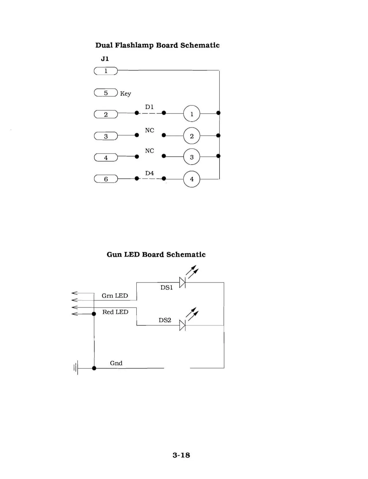
This page is a drawing, shown as the original scan.
This page reads as a drawing: its text was drawn rather than typeset, and comes out in fragments. See the original scan.
Frases "| nox
nr
um
oo ow on lex $0 atasel Sin Bas-} Sais tr
mew
sorcwcux
ast
rowan pracd
AX|comsaleerr Hr BEEN)
sor [ie eeacat por
cH os os
oo MU omer |
on
oun
ie ae ray Baw
u32 rowout
+ Touw
1 '
or a ites aja Xa
| 1 | ' | ' | ' | 1 | , | |
| ov or | Loh or | or or | ov op | Leer ar | or wr | or |
| oy | Soa | Soe “v | yoo | Soe | oa | |
| wa | [ws | [ws | ws | 7 | Tw k | Pek |
ey al ee * af ete” a] ca” 2] cts 2] cae a] att
Fas Sound Board sheet 2 of 4 (Music Synthesis)
3-20
lEc
Poof 2) |
; D
. C
. B
j A ee a ET 82h : aa ms , Sound Board sheet 3 of 4 aie (Amplifier)
3-21 ee a
al
Sound Board sheet 4 of 4
| esate | He | =F | ||
| oo | sama th | 2 | ||
| Ay | ee sora Ee | Tes | = | 0.0078 |
| " | 1 Hive ours LE | < |
0s on i * tive Si 1 # sais :
or a
we ~ Ho
| ‘im ura | | =o = = | 7 | |
| mga | = | : | 008 |
cre = II am =e
| waist | eed | res |
| 26L5I2A, | cry | 7) we |
7 oe ler To FE me arjore Tne He sone fe x seen :
| 0 | i | T |
is me Swe - -
‘Stn ae “ au
7 a4
| als | 7 | len To |
m
| ws | wa | aver | “one BE HE | sev |
on Ie tt me . som Ba EE
| ” | 100 oF | ” |
ot ‘
| vee | ar | 4 | i |
| SOFT_RES: | cas | id |
(Interface)
3-22
TE] PR eo & £ ae UL 7764
| D | , | roatas |
roatas
. roataa
To pin KKt00
pe
be
/ ‘ eset Us
sst0
oat
4 ae i Tey
| He HE | | | IDATAS | : |
| He | ele | - |
: . oats
;
oD “ a US
| A | “s | . | ee | 4 |
Coil Lamp Driver Board
sheet 1 of 3
| 8 3-23
[tev Tp eee ee) [ep ere [er7e4
be T1102 ay
pa mapi02
TIP 102
rap102
ae TIPIO2 =~.
tarie2
ais ¢
ovo ai Vv
: ComL-2 - = ON iy TIP 102 ag TIP 102 —
TUP02 no.
7 EREZS
1 Are
Coil Lamp Driver Board
sheet 3 of 3
2-25
+5 Volts DC “45 Volts DC |} Gry NC. . +12 Volts DC
Counter 1 NC Speaker (+) NC Video Red Video Blue Video Grd Test. 1 Coin JAMMA Chart
Ground Ground +5 VoltsDC +5 Volts DC NC | +12 Volts DC
Counter 2 © NC » Speaker NC Video Gr Video Sync Service Credit Slam Tilt 2 Coin 2 Start
Ground
3-26 Power Wiring Diagram See Note
! See Transformer Chart 1] fr
| rl | |\2 | Light Fixture | ||||
| 4 | 18 | > 60Hz | ||||
| | | [4] | [4 | eu __. soz | ||||
| [Luo | 1) | {1 | Lwo | ra | 11; | we |
| eve | le) iE YEL__§$_¢ | 2 -GRN______ Power Supply | ||||
| ry | albinos | 3||3 wove |
vio- yer | 4 || 4 |_vio- YE! | 2||2 [oan
| YEL | [7] | [7]—__savac]| | 9)2]/2 | Monitor |
YEL-WHT} 9 || 9 To _|}3]}3 [atx — ] 1? FOP Goin Door 4
| 7] | 24.5VAC | ‘GAN |
YEL-GAN | 9 | To Coil Lamp |-YEL-WHT | 3 | Driver Board YEL-WHT 4
Transformer Chart
15-pin Connector YEL
| From Power Switches | =1§ | tii—_0 | Mo | 3 re |
Ta 1 £8 | 120 isloated for x Monitor, Power Supply . and Flourescent Lamp.
| 9) | > | 120 | Ze |
2 By
| NOTE: | > |12| >+—BLK | 120. | . | ||
| Showres: | | s|>{suu-wir | 0 | oc | % | 24.8V for ols and |
| jumpered for | = | lashlamps. |
420V Vid WHT4 |<
| ‘operation. | 8 | BLU- BRN | 100 | QO. YEL-WHT 1 624 |
14| 5} BLU- RED 110 5.9V for coin door
| p—te | 43] 3] | BLU BLK | 120 | SA YEL | Lights. |
——fe| 7 | >} BLK yew 5610- 12945 - 00
| = |10] | | | —BLK |
=| 13) >-|—BLK Topower WHT RED 2 WHT - RED.
| Swiches | BLK: YEL | mya | $0 | pik ver | From Ube: |
Voltage Selection Table Voltage Jumper Pins ___Varistor_Fuse
| 100 | 5.6,7-8,9-10 | 130 | : |
| 420 | 5.6, 7-11, 10-12 | 130V | |
| 200 | 5-9, 10-8 | 275V |
210 | 5-9. 10-14 275V
| 220 | 5-9, 10-11 | 275V. |
| 230 | 5-12, 10-14 | 275V |
| 240 | 5-12, 10-11 | 275V |
Cabinet Wiring Diagram
JB “20 Pin Ribbon Cable
- Red Line on Ribbon Cables must go to Pin -1 on both boards. Ribbon Cables may need to be twisted to accomplish this.
J2
auvod ndd fs &
J3 zone
la Is J4 ie
L
Shielded Video Cable a ‘JAMMA Edge Connector £Z7Z7<S
Z BB o- | [oe
H ; P7 Pt
Sound Board fon [Fes=
[7 Seeman teens one 7) | Wiring Diagram Coil Lamp Driver Board
PS ET EES oe
Bons
Switcher meprae. Crested Transformer ‘Supply
woe couposire
Mowrror ‘BOARD
Main Harness Outputs Wiring Diagram
Coin Door
Wht-Org_Coin Meter Service/Credit Switch owned Main Harness
Wht-alu Coin t ~—_Wht-Vio Siam Tin F 0 1 Switch ae ae ry +5v atu “cain ‘Org. Wht 21] x
Volume 2/3} Control ale OKA,
Coin ‘ [Coin Chute
Meter ic Lights
#555 bulb or| Transformer equivaient
- Coin Meter 2 (optional)
Optional Coins 3-4 ECA Coin Door Inputs
Lamp 2
Dual Floshlamp Boards Player ‘See Control Panel Wiring Diagram on Next page
L_____» To Contro! Panel
Lamp 5
Lamps
Dual Flashlamp Boards Player 2
Lamp 7
Lamp 8
Main Harness
Control Panel Wiring Diagram
Player 1 and Player 2 Gun Assemblies Have Identical Wiring.
Gm-Yel_LED4 }44] }14 Key 10] Ho Bik-Yel__ Pot, Gnd Key
Gm-Gry Coil2_}12} j]12
| BkGm | _GmLEDLEDA | SM |
Gin-Blu o>
YolGm_startt_|2 NC Player 1 ‘Start
Yer-Biu stan2_|3 —Key__} Player 2 ‘Start | Player 1 Gun Control Panel Gry-Bly +5 Pot + Qro-Yel__Triggar oo Is |_Ora-Gmn__ Bomb ow | js | Bed __s2tv
| Is |_ Bk. | Switch/LED Gnd | } |
6 |__Bik-Bm__X-Axis (Horizontal) SKA
| |]? | |_-B&Or__v-Axis verican | aa | g | gun cot |
| lle | Bik-Yel__Pot, Gnd | + | " |
—Key—_10] |]10}_Key
| Bik-Grn LED2 }11] | 411] | BiG | Gin LED LED 2. | SM |
| Grn-Blu_Collt_}12} | ]12|_ | Grn-Blu Coil’ |
Player 2 Gun
| Gry-Blu | 1 | |‘) | |Go-Bl__ssv Pot | ||
| YetVio | 2 | jJ2 | |_-Oe¥et_ trigger | |||
| YerGry | a | [3 | |_Or9-Gm Bomb | rie | | ||
| V_sv.wne | la | lla | [Red | aaav | ||
| (ax | | | Hs | |_em | Switch/LED Gnd | |
| fe | He | [aK | X-Axis (Horizontal) | if | SK | |
| 7 | 17 | |_Bik-Red__ Red LED LED 3 | SD | 1 | ||
| 8 | |e | |_BikOr__ | y-Axis (Vertical) | bs | 3 | pce |
3-28 Notes
PC Board Jumper & Fuse Lists
CPU Board Jumpers W2, W8, W11, W12, W14, W21, W22, W24, W27, W29, W30, W32, W34, W36, W39, W41, W42, W45, W47, W48, W50, W52, W55, W57, W58, W60, W62, W65, W68, W69, W71, W73,
Sound Board Jumpers
Coil Lamp Driver Board Jumpers W1, W6, W7
Coil Lamp Driver Board Fuses Fl, F2 3A, F.B., 250V
F3 1A, F.B., 250V
F4 7A, S.B., 125V
WARNINGS & NOTICES
Warnin;
USE OF NON-MIDWAY PARTS OR CIRCUIT MODIFICATIONS MAY CAUSE SERIOUS INJURY
OR EQUIPMENT DAMAGE! USE ONLY MIDWAY AUTHORIZED PARTS.
- For safety and reliability, substitute parts and modifications are not recommended.
- Substitute parts or modifications may void FCC type acceptance.
- This game is protected by federal copyright, trademark and patent laws. Unauthorized modifications may be illegal under Federal law. This also applies to MIDWAY logos, designs, publications and assemblies. Moreover, facsimiles of MIDWAY equipment (or any feature thereof) may be illegal under federal law, regardless of whether or not such facsimiles are manufactured with MIDWAY components.
Warnin;
Notice When MIDWAY ships a game, it is in compliance with FCC regulations. Your sticker is proof. If the sticker is missing or damaged, legal repercussions to the owner or distributor of the game may result. If your game does not contain an FCC sticker, call MIDWAY immediately.
Notice No part of this publication may be reproduced by any mechanical, photographic, or electronic process, or in the form of a phonographic recording, nor may be transmitted, or otherwise copied for public or private use, without permission from the publisher.
© 1991 Midway® Manufacturing Company © 1991 Terminator™ 2: Judgment Day, Endoskeleton™ and Depiction of Endoskeleton™ are Trademarks of Carolco Pictures Inc. Sublicensed by Midway Manufacturing Company from Acclaim Entertainment, Inc. All Right Reserved. Unauthorized Duplication is Strictly Prohibited.
For Service: CALL YOUR AUTHORIZED MIDWAY DISTRIBUTOR.
MIDWAY Manufacturing Comapny 3401 N. CALIFORNIA AVE. CHICAGO, IL 60618