Crazy Climber Upright (Taito)
Crazy Climber (Bandai) (Bandai, 1982) · Document · 26 pages · 9 sections · original scan
1981 Trade Marks of Taito Amance Corporation 72.00001-002
CRAZY CLIMBER-UPRIGHT
TABLE OF CONTENTS
CRAZY CLIMBER GAME SET-UP
A. Introduction
B. Game Inspection
C. Game Installation
D. Dip Switch & Volume Control Settings
MAINTENANCE
Cleaning
Fuse Replacement
Video Monitor Removal 9°: 2 > Video Monitor Adjustments
E. Fluorescent Butb Replacement
F. Printed Circuit Board Replacement
ILLUSTRATIONS AND PART LISTS
Figure 1 Video and Cabinet Assembly
Figure 2 Coin Mechanisms and Front Door
Figure 3 Switching Regulator & Cabinet Parts
Figure 4 8-Way Joystick Assembly
Figure 5 Contro! Panel
Figure 6 CPU Board ‘‘A” & Component List
Figure 7 CPU Board “‘B’’ & Component List
Figure 8 Option Switch & Volume Control Locations
Figure 9 Wiring Diagram
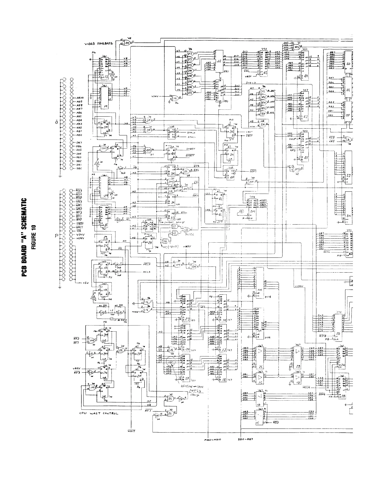
Figure 10 PCB Board ‘A’ Schematic (FOLD OUT)
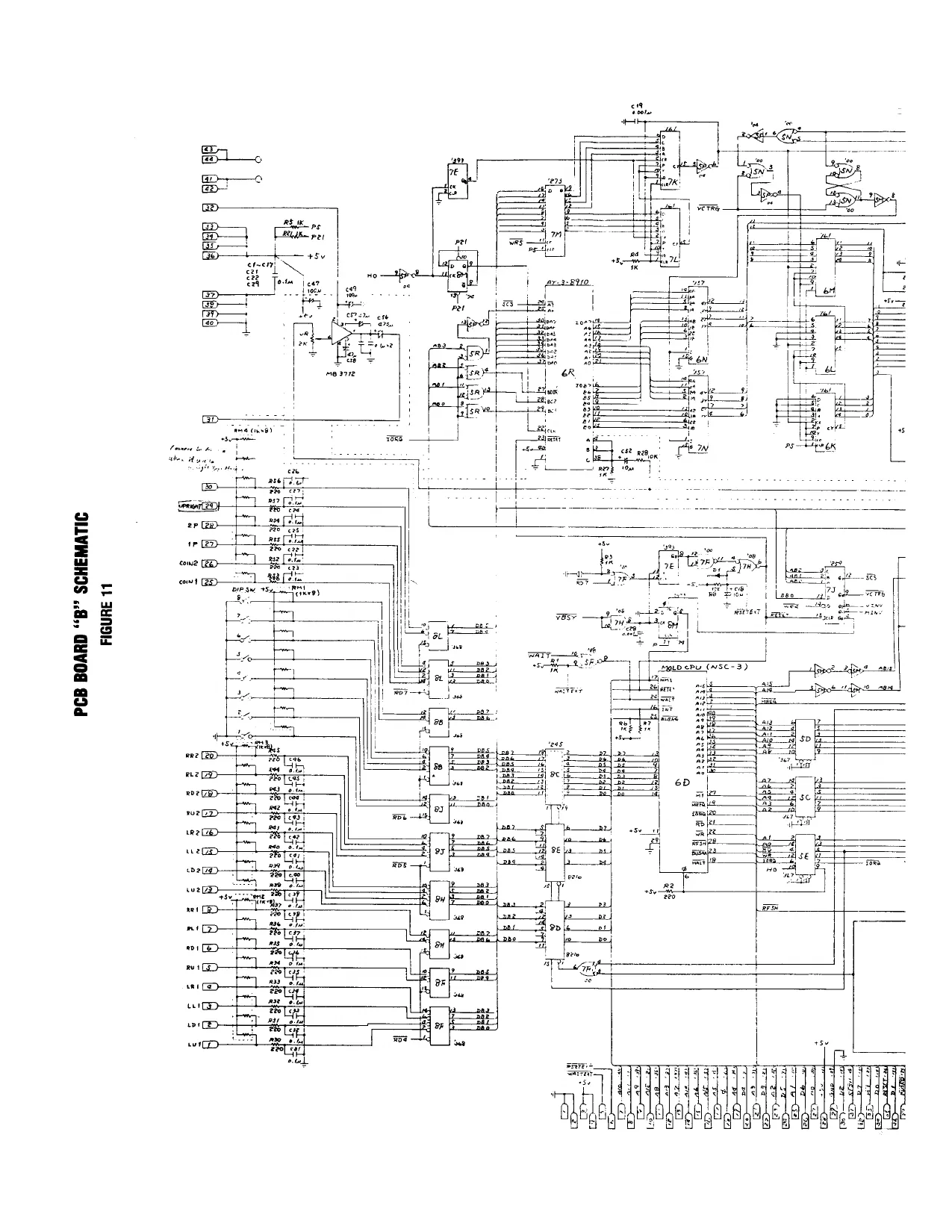
Figure 11. PCB Board ‘‘B’’ Schematic (FOLD OUT)
GAME SET-UP
INTRODUCTION
TAITO AMERICA’S CRAZY CLIMBER UPRIGHT is a skill based video action game, with speech, designed for one or two players.
The object of the CRAZY CLIMBER game is to advance the climber to the top of each skyscraper attempting to avoid the various obstacles. A player can scale up to a total of four skyscrapers. A player accumulates point value for climbing and then receives these points if he is picked up by the helicopter at the top of each skyscraper. If the player misses the helicopter the bonus points are lost and the player advances to the next skyscraper. An additional climber is displayed if the players score reaches 30,000 points (adjustable) .
GAME INSPECTION
TAITO AMERICA’S CRAZY CLIMBER game is ready to play when received. However, careful inspection is necessary to insure your game is in perfect condition. Please verify the following before turning the game on.
- Examine external parts for chips, dents, or broken parts.
- Open the service door and examine the following: Plug-in connectors to make sure they are firmly seated. Speaker Player controls. Printed circuit boards making sure there is no damage to the components.
- Check for loose foreign objects especially metal objects which may cause electrical problems. Fuses, making sure they are firmly in the holders. Transformer Coin Mechanisms
If problems occur or technical assistance is required, contact our Customer Service Department HOT LINE Toll Free 800-323-0666 (except Illinois). Minois phone 981-1000 X 215.
The Video Monitor is properly adjusted before shipping, if there are any adjustments necessary refer to the manufacturers operating manual.
POWER REQUIREMENTS
TAITO AMERICA’S CRAZY CLIMBER game is shipped ready for operation at 120VAC, 60Hz with a power consumption of approximately 250 Watts.
For sate operation it is recommended the cabinet be grounded. This game is equipped with a three conductor power cable. The third conductor is the ground conductor and when the cable is plugged into an appropriate receptable, the game is grounded. The offset pin on the power cable’s three-prong connector is the ground connection.
LOCATION SPACE REQUIREMENTS
Depth - 35” (87.5cm) Width - 24” (61cm) Height - 68" (171cm) Weight - 300 Ibs. (135Kg) INSTALLATION REQUIREMENTS The following precautions should be followed when installing the game.
- Avoid rough handling of the game, the picture tube is fragile.
- Install the game on a level surface.
- Avoid installing the game where it may receive excessive sunlight or heat, to prevent the game from rising internal temperature.
- Do not install in a damp or dusty location.
- For a short time after connecting the power to the game, the picture may be temporarily distorted.
DIP SWITCH AND VOLUME CONTROL SETTINGS
DIP SWITCH SETTINGS TAITO AMERICA’S CRAZY CLIMBER game provides the following option switches. See Figure 8. These options can be found on PC Board “A” Switch B.
SW 1 and SW2 are used for selecting the number of climbers. Switches 1 and 2 are preset at the factory for 4 climbers.
CLIMBERS swt sw2 3 | OFF | OFF
| 4 | ON | OFF |
| 5 | OFF | ON |
| 6 | ON | ON |
TABLE 1 CLIMBER OPTION
- SW3 is used for adjusting the score at which time an additional climber is added. Switch 3 is preset at the factory for 30,000 points.
OFF 30,000 ON 50,000
TABLE 2 CLIMBER SCORING OPTION
- SW4 when in the ON position displays a test pattern and runs through four screens.
- SW5 & SW6 are used for coin selection. Switches 5 and 6 are preset at the factory for 1 coin - 1 play.
| COIN SELECTION | SWS | SWE |
| 1 coin - 1 play | OFF | OFF |
| 2 coin - 1 play | ON | OFF |
| 3 coin - 1 play | OFF | ON |
| 4 coin - 1 play | ON | ON |
TABLE 3 COIN SELECTION OPTION
- SW7 & SW68 are normally in the OFF position uniess used for a free play. Then both switches should be in the ON position.
Switches must not be adjusted unless the power is off.
VOLUME CONTROL SETTING
- VR. This option switch is used to contro! the volume. See Figure
- Volume goes down in turning as the arrow indicates.
MAINTENANCE All games require a certain amount of maintenance to keep them in good condition. A periodic check of mechanical controls would be beneficial to guarantee your game will be profitable.
CLEANING The exterior of the game, all metal parts and all plastic parts can be cleaned with an non-abrasive cleanser. Caution should be used when cleaning the plastic, a dry cloth can cause scratches and result in a foggy appearance.
FUSE REPLACEMENT This game uses six fuses, 5 are located on the Switching Regulator. See Figure 3 for size and part number of fuses. One fuse is located on the Power Supply itself.
VIDEO MONITOR REMOVAL \f you need to remove the video monitor, follow the instructions listed below:
It is recommended the game be left disconnected for at least one hour before removing the video monitor. This will probably discharge the video tube but extreme caution is still necessary.
Remove power from line voltage. Disconnect the monitor and cable connector. Remove wire cable clamp. Take out the two side bolts, one on each side of the cabinet. Lower the monitor to rest on the lower set of wood supports. Remove the four mounting bolts and disconnect the green ground wire. Slide the monitor out by pulling the monitor towards you.
Use extreme caution and do not touch electrical parts of the monitor yoke area with your hands or with any metal object in your hands! High voltages may exist in any monitor, even with power disconnected.
VIDEO MONITOR ADJUSTMENTS
The Video Monitor is factory adjusted. If there is a need for readjustments after the game has been shipped please refer to the manufacturers operating manual.
FLUORESCENT TUBE REPLACEMENT
Ifyou drop a fluorescent tube and it breaks it will explode! Please use care when replacing.
To replace the fluorescent bulb the contro! panel must be removed. With both hands turn the bulb toward you and carefully pull out of the lamp. socket. PRINTED CIRCUIT BOARD REPLACEMENT
You may wish to remove the CRAZY CLIMBER printed circuit boards for replacement or service. Follow the procedure beiow.
To remove the ‘'A’’ Board (08-00005-002) and/or the ““B’’ Board (08-00005-003) slide the double layered board set out of the guides.
This equipment generates, uses, and can radiate radio frequency energy and if not installed and used in accordance with the instruction manual, may cause interference to radio communications. As temporarily permitted by regulation it has not been tested for compliance pursuant to Subpart J of Part 15 of FCC Rules, which are designed to provide reasonable protection against such interference. Operation of this equipment in a residential area is likely to cause interference in which case the user at his own expense will be required to take whatever Measures may be required to correct the interference.
VIDEO AND CABINET ASSEMBLY
TAITO
| ITEM | PART NO. | DESCRIPTION | REFERENCE |
| 1 | 47-00001-001 |Screened Acrylic Marquee Panel | 400073 | |
| 2 | 27-00001-001 |Fiuorescent Tube, Std., 15W | AA054711 | |
| 3 | 42B-00057-001 |Fluorescent Lamp Panel | 140006 | |
| 4 | 26-00004-001 |Lamp Socket (Holder) | 113000 | |
| 5 | 61C-00007-001 |Glass Stop Bracket | 500024 | |
| 6 | 26-00005-001 |Starter Socket | 114001 | |
| 7 | 29-06003-001 | Starter | 114000 | |
| 8 | 18-00002-002 [Ballast Transformer | 010006 | |
| 9 | 61B-0001 1-001 |‘'L”’ Bracket | AA013584 | |
| 10 | 04-00008-001 |Cabinet Assembly | 860007 | |
| " | 63B-00006-001 |T Moiding, Chrome | 400007 | |
| 12 | 59-00008-001 |Clamp Fastener | 390002 | |
| 13 | 47D-00002-001 |Cover Glass Assembly | 148011 | |
| 14 | 63C-00003-001 | Monitor Shround | 400005 | |
| 15 | 61C-00016-001 |Glass Retaining Bracket | §00022 | |
| 16 | 44C-00001-001 |Caster | 520000 | |
| 7 | 63B-00005-002/L Molding, Black, 22%” Long | 400031-A | |
| 18 | 63B-00005-003|L Molding, Black, 3334” Long | 400031-B |
31-00001-001
| 19 | 31-00001-002 |Monitor, 19” Color | 840017 | |
| 20 | 61C-00004-001 |Video Mounting Bracket | 500026 | |
| 21 | 45-00001-001 [Anchor Plate | 600005-C | |
| 22 | 45-00001-001 [Service Lock & Key | 600005 | |
| 23 | 41C-00035-001 | Cabinet Back | 143003 | |
| 24 | 61B-00027-001 |Ventilator Screen | EP030010 | |
| 25 | 500086 | Bracket Top | AA013580 |
| 26 | 500088 | Cash Case | AA028507 |
| 27 | 400050 | Cash Box | AA028506 |
| 28 | 600007 | Lock Plate | AA013583 |
| 29 | 500089 | Cash Box Door | AA026512 |
| 30 | 600006 | Lock (Cash Box) & Key | AA016545 |
| 31 | 500060 | Coin Funnel | AA025510 |
| 32 | 500062 | Coin Funnel Plate | AA013690 |
| 33 | 115000 | Counter, 6V DC | AA0S1717 |
| 34 | 500091 | Counter Bracket | AA013608 |
| 35 | 63B-00006-004|U Channel Black | 400025 | |
| 36 | 500087 | Bracket Bottom | 50087 |
| 37 | 800011 | Counter Drive Credit Board | AAMS0012 |
| 38 | 800011 | 10 Position Edge Connector | AAMS0012 |
| 39 | 500035 | Credit Board Bracket |
*40 08-00005-002 |PCB “A” “41 08-00005-003 |PCB “B’’
“Not Shown on Figure 1
This page carries no recoverable text. It is a drawing or a photograph. See the original scan.
COIN MECHANISM AND FRONT DOOR ASSEMBLY
TAITO
| ITEM | PART NO. | DESCRIPTION | REFERENCE |
| 1 | 500010 | Door Frame | AA026510 |
| 2 | 400047 | Price Card U.S. 25¢ | AA029512 |
| 3 | 110000 | Pilot Lamp, 12V, 150Ma. | AA054704 |
| 4 | 113001 | Vinyl Socket | AA055698 |
| 5 | 500124 | Coin Entry Plate for 25¢ | |
| 6 | 500021 | Service Lock & Key No. 7900 | AA016558 |
| 7 | 120017 | Taito Name Tag | |
| 8 | 500009 | Coin Rejector Door | AA026511 |
| 9 | 50021-E | Cover Plate | AA019522 |
| 10 | 104000 | Mate-N-Loc Pin A | AA055789 |
| 1 | 103007 | Mate-N-Loc Housing 9P | AA055581 |
| 12 | 103008 | Mate-N-Loc Housing 9P | AA055582 |
| 13 | 104001 | Mate-N-Loc Pin 1B | AA055790 |
| 14 | 500021-1 | Lock Plate | AA013578 |
| 15 | 500021-G | Coin Guide (B) | AA025508 |
| 16 | 500021-H | Coin Guide (A) | AA025507 |
| 17 | 500021-J | Tilt Switch | AA068717 |
| 18 | 500058 | Lock Guard | AA013577 |
| 19 | 500021-K | Rejector Button | AA027504 |
| 20 | 500021-L | Spring Cancel Holder | AA015504 |
| 21 | 020501 | Service Switch | AA052531 |
| 22 | 500021-M | Cancel Lever | AA013557 |
| 23 | 500021-N | Rejector Bracket | AA013554 |
| 24 | 500021-P | Rejector Holder | AA023501 |
| 25 | 500054 | Coin Guide | |
| 26 | 199005 | Insulator | AA019502 |
| 27 | 020502 | Micro Switch | AA052512 |
| 28 | 370002 | Actuator | AA053501 |
| 29 | 500021-R | Rejector Lever Connector |
foe) N LP LE 4 © S
xX w . M, Ee, _ ‘\
Ne 6 y : Vie ” Wek G7 __&p _ N y Z = SS
& Qa B
- > — \ Ss -
4 \Y ae wh
WSO
SWITCHING REGULATOR & CABINET PARTS
TAITO
| ITEM | PART NO. | DESCRIPTION | REFERENCE |
| 800010 | Switching Regulator PCB Assembly | AA055720 | |
| 998702 | Shield Box | AA013613 |
228-00001-004] Power Line Filter 26-00003-001 | Service Outlet 24-00002-002 | Fuse, 1.5 AMP, 3AG, Slo-Blo, 250V 24-00002-001 | Fuse, 3AMP, 3 AG, Slo-Blo, 250V 24-00001-001 | Fuse Holder 35-00001-001 | Barrier Strip, 8 Position 42-00034-001 | Power Board 61-00030-001 | Switch, Interlock SB) elalnlo)gla}alelr|= 29-00004-001 | Toggle Power Switch 1 35B-00002-001) Insulating Shield 12 18A-00001-001) Isolation Transformer
| 13 | 998962 | Noise Filter | AAT61017 |
| 14 | 998703 | Shield Cover |
15 61B00003-001 | Bracket Interlock Switch
SWITCHING REGULATOR & CABINET PARTS
8-WAY JOYSTICK ASSEMBLY
TAITO
| TEM | PART NO. | DESCRIPTION | REFERENCE |
| 1 | 400026 | Color Ball | BP090003 |
| 2 | 500153 | Control Lever | uwoz20001 |
| 3 | 400030 | Mask | RT090009 |
| | 4 | 500154 | Joystick “Base” | RFO30002 |
| 5 | 390041 | Plain Washer | AAL61027 |
| 6 | 370007 | Spring | RFO60001 |
| 7 | 500155 | Joystick “Base” | RFO30003 |
| 8 | 500156 | Center Ball | RFO20005 |
| 9 | 500157 | Center Ball Cover | RFO30004 |
| 10 | 500158 | Collar | RFO20002 |
| 1 | 500159 | Actuator Push Plate | RF030007 |
| 12 | 500160 | Push Plate Guide | RFO30005 |
| 13 | 500164 | M.S. Base | RFO30001 |
| 14 | 390042 | Spacer | RFO20003 |
| 15 | 020503 | Micro Switch | AA052532 |
| 16 | 199010 | Insulator V Type | AA019504 |
| 7 | 500162 | Block | RFO20006 |
| 18 | 390043 | Snap Pin | |
| 19 | 500163 | Lock Plate | RFO30006 |
mi
8-WAY JOYSTICK ASSEMBLY
CONTROL PANEL ASSEMBLY
TAITO
| ITEM | PART NO. | DESCRIPTION | REFERENCE |
| 1 | 850042 | Joystick Assembly (8-way) | UWKO00005 |
2 42D00033-001 | Control Panel (Wood) | 3 61A00015-001 | Strike Hook
| 4 | 850003 | Push Button Assembly (White) |
CONTROL PANEL ASSEMBLY
T s__4
This page reads as a drawing: its text was drawn rather than typeset, and comes out in fragments. See the original scan.
con & TA1S161 & 74ise6 tSPic is ] 2picu | ‘TALS86 om ssiez ] ALS 283
IR pyc 16
[eg NG RHIC i 3RP Ic 22 TALSIO & 718.273 oO TASB6_ io) Ata 1495
asp IC 21 TAL5134 ss bic i TALSIY4 a MULSVTS: rt
- Ic 18 S02
mpic &
7428 a ol n
=
a- Ee a TL $273
sRDIC IT mpic 8 | gi 2) = ES
= Ss i 71_1R
TALS O07 gerbes TALS 74 T4H1532 al SA
Tas TALS Ta Pb ita tt applic 0} eb ie 5 ap BIC 13 sPbIc 2 6P Ic iy
TALSOA TALS 74 1S WLS T4, FALSOB,
INDIC 3 wbic 10] pici0 bicto swPic 4 | #
74 500 TALSTA M1532 aN TALS 21 AUST
imp Ic) Bic oO | aM pic 7 am BIC 7 eM Pic 17
TAL S26, WLIKUYE TAS 14 TL8137_ 6
Wplert “es 2 157 = TSA se bic 3 J
3 DIC 4 4 ses 10 Qrusis TALSIST nso
TAN SIST gneic) I*PIC 10 aK STC 13 4D IC 14
TALSIST THUS 134 THLSIST PICS Tq MBSII4N)
whic 4 | abic 4 3 ple 13 ATDIC 1 Srp IC 26
MB AANL PAL SIST T4LS161 ‘T4HLS86 MBaI4NL 6H
MPI Jo) 2 ic 14 a4 Pic subic 26] ROM 6 [Rom 6] ar [e) KOM 5 cc-5 ¢2 PIC 4 TALSO2 epic vy T DSA,
mpc 2 Titswa 8H DIC 27 T 215A.
Mp ic 4 c whic '7 ASI Mi ICY TALSIIG, Ic 27 BMD Tht M
8 Dic 27 1415134 apie 3 JL q mm KE |
oa Wmisins |
ma Dite 14 TALS, vgs
- pIC27 pic 16 |J
ML 536 96C
TANS Rb
mOiIC 19 lit |H
BH DIC 1) 4H
g TALSIST g ebtee ‘TALS36T MB STIG WL epic Je] LSI'T cov T4LSt5: aF Dic 4 C2 Ornusis1 ve PTC 1+
TH S86 ‘1415367. T4LS 245 cc-3 i TALSIST TALS 02 T4LS163 TALS)
oF Dic wD AC 2
cr —7atsi5 oe Pic 14 ALSIST pple a bic? |F 8F_ oD 7
TANSNA
TE DIC 14
‘749273 1415194 oNC2 | pic | waa EI | ‘misith !
whic 23 | | TALS27I DD! 1c 7} sepic i app ic 23 1¢ 20 6eb Ic ‘wp ic 19 eb iy
415367 7415367 141536, THLS 367
te Hic 23 T4LS107
ne achic 23 } TALS367 sect ‘7415161 ac PIC 2: sch 1¢ le
TALS]
th 1c 12_] 28H ic 23 36 BIC 15 4BP IC 6
Ww Thi 5361 TAL SIBY 741586
zz la ABM iap 1c 2 apicu | 741515" 4apic 14] 5a
tm OF Bp | C2 O02 oe (T= Iss b Ic 25 ’
MBBIOIN
MB BIOIN TS2 oa TALS 194
Row a cC-2 Ceca ROM I i (f-1 c 183
ca pic ig T4194 76 pic 19 ALSN94 grbic is] Hig ac PROM A rr B Al |
i o
oO, C.P.U. BOARD “A”
CPU BOARD “B” & COMPONENT LIST
TAITO TAITO
| Tem | PART NO. | | DESCRIPTION | REFERENCE | TTEM| PART NO. —_| DESCRIPTION | REFERENCE |
| 1 | {79-00013-001 | PC Board Sticker | 31 _| 16-00001-107 | Rom 7 CC-7A 2732 | ||
| [ 2 | |29-00008-001 | Dip Switch DDS-6 | ‘AAO 52566 | 32 | _|16-00001-108 | Rom BA P-Rom CC-8 2732 |
| 3 | _|28-00001-024 | IC Socket 24° | ‘AAO 55787 | 33 | 46-00001-009 | Rom 9 P-Rom CC-9 2732 | |
| 4 | _|26-00001-040 | 1C Socket 40P | AAO 55812 | 34 | 16-00001-010 | Rom 10 P-Rom CC-10 2732 |
5 | 25-00004-001 | PC Board Conn. 35 | 16-00001-011 | Rom 11 P-Rom CC-11 2732
| eens | [36 | _[16-00001-012 [ Ram 12A P-Rom CO-12 2732 | |||
| 8_|25-00021-00r | Angle Pin Header PS SOPA_| | AAO 55164 | 371 | 16-00001-173 | Rom 134 F-Rom Co-19 2732 | ||
| 7 | _{11-60001-202 | Variable Res 2k Pt | 38 | [12-10002-102 | C1 Cap-Ceramic 0.00uts0V | AAT 41399 | ||
| | 8 | 18-00002-001 | Diode ($1588 | as) | 39 _ | 12-10002-104 | C2 Cap-Ceramic 0.1ufS0V__ | | AAT 41672 | ||
| § | _{i15:50003-001 | OP Amp MB $712 | AATSIO2 | 40 | _[412-40001-105 | C3 Cap, Tantalum 1uf25V_| | AAT 41425 |
| 10 | _|15-20000-001 | IC 1 LS IC 741800 | AAT 33001 | 41_[12-40001-106 | 4 Cap, Tantalum 10uf25v_| | AAT 41430 | |
| 11_{18-20002-001 | 1G 2 LS 1¢ 74LS02 | sea | [42 | | 12-50001-476 | C5 Cap, Tantalum 47uf35v | AAT 41657 | ||
| 12 _ | 15-20004-001 | 1¢ 3 LS Ic 741804 | AAT 33005 | 43 | |12-20001-107 | 6 Cap, Electrolytic | ||
| 13 | 15-20008-001 | 1c | 418 IC 741808 | ‘AAT 33009 | 25VB 100ut | AAT 41036 | |
| 14 _ | ¥5-20032-001 | 1c 5 LS IC 741832 | AAT 33027 | 44 | |12-20001-477 | C7 Cap, Electrolytic | ||
| 15 | _[15-20042-001 | IC 6 LS IC 74/842 | AAT 33032 | 25VB 470ui | AAT 41039 |
7 45 | 44-00001-221 | R 1 Res, Carbon 46 | 11-00001-102 | R 2 Res, Carbon 1K AAT 51765
| 18 | _|15-20138-001 | Ic 9 LS Ic 7418138 | AAT 33096 | ae | Tyroo001-103 TA Res. Carbon 10K | ear Sirs | |
| 19 | _{15-20139-001 | 1C10 LS IC 7418139 | AAT 33097 | ga | Trronnota3 | Ra | Res. Carbon 18K | AAT STO |
| 20 _ | 15-20157-001 | Ict1 LS IC 7418157 | AAT 33112 | 79} | 11000012731 | RS Res, Carbon 57K | MAT S179 | |
| 21 | [16-20161-001 | IG12 LS IC 7418161 | AAT 33116 | : | |||
| 22 _ [15-20174-001 | 1013 LS IC 7418174 | AAT 33127 | 50_{11-00001-478 | B 6 Res, Carton 47 | MAT 1805 | |||
| oa | Tesapeeonr | [GRE FL | ans | sais | 51 | 44-00001-104] R 7 Res, Carbon 100K _| AAT 51803 |
= = 52 | 11-00001-204| R 8 Res, Carbon 200K _| AAT 51820 24 _ | 15-20273-001 | IC15 LS IC 7418273 AAT 83170 53 _|11-00001-394 | R_9 Res, Carbon 300K _| AAT 51827
| 25 | _|15-20367-001 | IC16 LS IC 7418367 | AAT 33203 | {2 |
54 | 17-00001-824 | R10 Res, Carbon 820K _| AAT 51835
| 26 | _[16-20368-001 | IC17 LS IC 7418368 | AAT 33204 | = | | |
55 | 11-50001-010 | RB1 Resistor Block 1ohmx8 | AAT 55036
| 27 | {15-20393-001 | 1C18 LS IC 7418393 | AAT 33220 | 5 | T-00008-001 | custom Module | ||
| ad | — | = ae a | “ as —| | [57 | |15-44086-001 | 1022 ¢ Mos IC MC14066 | | AAT 36067 |
ald 1 58 | 15-20245-001 | 1023 Ls IC 74L8248 [AAT 33187 30 | 45-60003-001 | 121 Sound Ic AY-3-8910 | AAT 92165
This page reads as a drawing: its text was drawn rather than typeset, and comes out in fragments. See the original scan.
OPTION SWITCH & VOLUME CONTROL LOCATIONS
Board “B”
Game
PC. Boaro Assy. O8- Xc005 -00} (Boaro | or 2)
COUNTER
DRIVE
PC. BL 26-0000!- 00/
di oe
ati 12345 67890/D As a Bue
(Boarv 2 oF 2) MoniToR evecrtohone aa wees | Fame, sto-B.0~ \20 vac Coane stabi 20 Ae Oi wee hat 3 | 4
GarDueR | — Yirai U __f pi st ey maeur Pa 5 5 wrens ; i t ‘ i ' ' i —oe an poueR! bBawe go] ME pay Fovogesent ! i7—_| jue 15 |_ Bux. NOISE FATER
[nese Quer Use) ur one, f SWITCHING
REGULATOR
ofan erees 45YASSY. I 07-0000) 001 fF -5v (Ner Use0) BAY Paw 3K For 120 wc - ‘ies Wn 1014 4 Wine Buc 36 For 220 vac- Wits Warato |, Sumner 2104 7 Ra
NEEL So Power Boe ic ASSEMBLY a WIRING DIAGRAM
NOTES
This page is a drawing, shown as the original scan.
berate hhlin
sng Qn) ent elo | i m4 ner
ai@lalaja
au 43\_an| ae | ae |e7s2ress2
ry work nig AREA Rat (Boon~ 2978) ELT UT Y
eV Py
This page is a drawing, shown as the original scan.
Ay &
iz
fh it aS i i ll [
i 7] ie I kbp FREER
This page carries no recoverable text. It is a drawing or a photograph. See the original scan.