Top Speed Instruction Manual
Top Speed (World, rev 1) (Taito Corporation Japan, 1987) · Instruction Manual · 23 pages · 15 sections · original scan
This page carries no recoverable text. It is a drawing or a photograph. See the original scan.
® 1987 Romstar Inc. All Rights Reserved.
No part of this manual may be reproduced by any mechanical, photographic or electronic process, or in the form of a phonographic recording, nor may it be stored in a retrieval system, transmitted, or otherwise copied for public or private use, without permission from the publisher.
The game play, all graphic designs, this technical manual, its accompanying diagrams, and the display manual are protected by the law.
You may void the game warranty if you do any of the following: @ substitute non-Romstar Top Speed electronic parts in the game
© modify or alter any circuits in the game by using kits or parts not supplied by Romstar.
IV. STEERING WHEEL EXPLODED VIEW.............000005 te eeeeeeececoseees 7
A. STEERING WHEEL COMPONENTS / PARTS NUMBERS............... 8 V. GEAR SHIFT UNIT EXPLODED VIEW.........00ccecceccscceeereenececceres 9
A. GEAR SHIFT UNIT COMPONENTS / PART NUMBERS... 10 VI. SINGLE PEDAL ASSEMBLY EXPLODED VIEW .............cecesceseeees 11
A. SINGLE PEDAL ASSEMBLY COMPONENTS / PARTS NUMBERS.... 12 Vil. LAYOUTS
A. MAIN HARNESS PIN OUTPUT .............cccccccceseescccceceeeesees 13
B. MAIN HARNESS WIRING DIAGRAM................cccceeeeeeereeeeee 14
C. AC AND GROUND SIDEWALL HARNESS.. 15
D. POWER SUPPLY AND WIRING DIAGRAM .................00005 - 16
E. STEERING OPTIC PCB ....... ccc cccccccccccccccececnececccsnnseseeves 17 VII. LIMITED WARRANTY. ..........00s0ecssecccccececeeceeueeucceusscecassase 18
A. FBI WARNING ..........ccceceececcccccecencncccceeessnscsececesencoes 19
IX. COMMENTS.......ccccccccccccctccsnnntenececsceeeesueeuseeceuccesesoures 20
oovrvo0ofr FOO0O0ONn=
cord LOCATION AND SETUP
INSPECTION Remove the game from its shipping carton. inspect the entire outside of it for any signs of damage. Any scratches?, dents?, cracks? Any broken controls? Just look it over closely and make a note of any signs of damage. Remove the shipping cleats from the bottom of the cabinet. Install the four levelers, one at each corner of the cabinet. Level the cabinet. Open the cabinet and inspect the inside of the game for any signs of damage. Also check to make sure all plug-in connectors on the wire harness are firmly seated. Replug any connectors found unplugged. DO NOT FORCE PLUGS INTO CONNECTORS. DO NOT FORCE PLUGS TOGETHER. If it won't go on easily, assuming the keys are lined up, it either does not belong there or is damaged. Make sure all printed circuit boards (P.C.B.'s) are firmly seated in their connectors. These connectors are also keyed. The P.C.B.’s will only go into them one way without being damaged.
Power supply. Control panel(s). TV. monitor. Other P.C.B.'s and/or P.C.B. rack, ete. Power Chassis.
. Make a note of any problems that can’t be easily corrected. . Call your distributor and/or service man about your problem list.
“16
r i
i t TOP SPEED DIPSW-A $ es Oe | ee CABINET *STANDARD STYLE
*YES ATTRACT SOUND
*1COIN- 1 PLAY
1 COIN-2 PLAY
SS
DIP SW-B
DIFFICULTY
- ROMSTAR RECOMMENDED SETTING
CABINET WIRING HARNESS ROUTING
COIN METER
ACCEL. MARQUEE
A/C FAN
GAME BOARD
COIN DOOR MAINTENANCE
The magnet that is fitted to the mechanism, should be kept clean from foreign particles. The magnet can be cleaned by swinging the gate open. (as shown in Fig. 1). Remove metal filings from the magnet by guiding the pointofascrewdriver along the edges of the magnet, such that the filings cling to the screwdriver.
The mechanism can be cleaned by immersing in water using a small brush to clean the mechanism. Rinse the mechanism with boiling water and dry with compressed air.
If the above procedures are not successful, check for worn, bent or damaged parts and replace where necessary. Removal of Mechanism
To remove the coin selector: Unscrew the two screws (as shown in Fig. 2) — swing rear of selector body away from the lock-out side and withdraw.
The Gold Mech Acceptors are designed to require a minimum of maintenance and field adjustment. Coins are checked by diameter and thickness, weight, metal content, bounce, and for ferromagnetic coins such as nickel and steel, a rim test also used.
Coin Switch
The coin switch comes in two different spring tensions — identified by the color of the plastic boss at the wire's pivot point.
Red: Light tension- U.S. .25¢
White: Heavy tension-heavy foreign coins
CHASSIS - GROUND LAYOUT and ROUTING
CONTROL PANEL ‘
POWER SUPPLY
SO. TRANSFORMER
FILTER
STEERING WHEEL EXPLODED VIEW
STEERING WHEEL COMPONENTS
DESCRIPTION
Stainless Steel Disk 6 x18 I10 TCE Screws ‘Steering Wheel w/Disc Steering Wheel
12 MO Hexagonal Nut 0 12 Elastic Washer Hub Shaft 10x 20 MO TE Screws ; Casing 6002 Bearing Steering Mechanism : . 4x10 MO TCC Screws Polyamide Bushing i ‘Spacers 100 Elastic Washer 10 11 0 Hexagonal Nut Stop ring, External 0 6
Support Plate 10 O Flat Washer 2 60 Gear Wheel 10 M O Self-Locking Hexagonal Nut Steering Mechanism 2 14 Serrated Shaft General Pulse Bell 5 O Serrated Washer 5x8 MO TCC Screws
GEAR SHIFT UNIT EXPLODED VIEW
\ GEAR SHIFT UNIT COMPONENTS
ROMSTAI DESCRIPTION . PART NO.
Ball / Knob Template 5x16 MO Screws T.T.Q.S. Unit 5732 Axis Stop Ring Spring Polyamide Runner Casing Central Hub Rubber Buffers Spacers Cable Pivot Side Piate Floating Bar Flat Washers 5/15 0 Hexagonal Nuts 5 MO Serrated Washer 5 0 Hexagonal Nuts 5M 0 Elastic Washer 0 6 Hexagonal Nuts 6 MO 4 M O Solf-Locking Hexagonal! Nut 6x10 MO T.E. Screws 5x35 MO T.E. Screws Serrated Washer 5 O Microswitch 4x25 MO T.C. Screws 3x15 MO T.C. Screws Serrated Washers 3 0 Hexagonal Nuts 3 MO Entire Gear Shift Unit
= w > Qa wi ra}
a > ui re = rr a < ad
a ul a wi a So E= 7)
SINGLE PEDAL ASSEMBLY COMPONENTS
ROMSTAR DESCRIPTION PART NO.
Pedal Control Lever Frontal Plate Left Side Plate Right Side Plate Spring Connection Linkage Spacers Spacers with Shock Absorber Cam Microswitch 5x55 0 T.C.P. Screws 5x12 MO T.T.L. Screws Unit 5731-65 4x12M0 S.T.IE. Screws 4x20 MO T.C.P. Screws 3x20 M O T.C.P. Screws 3 M O Hexagonal Nuts 5 O Hexagonal Nuts 5 O Serrated Washers 4 M O Self-Locking Hexagonal Nuts 5 O Flat Washer Sector In Serrated Nylon
MAIN HARNESS PIN OUTPUT ROMSTAR - TOP SPEED 56 PIN CONN. @ PCB [_WIRECOLOR | SOLDERSIDE. | | ~=—Ss| ~—SsSPARTSSIDE |S WIRECOLOR _| a
| (pr) BLK | Gn. Lt & Swg. GND | [2 | | ‘GND (PwrSply) | [ak CS |
| —tunox ee ____{___as___}¢ af _ag_} __agp
| (Jmpr.) RED | (Steering) +5 | fo [4 [+s | re |
[mye | C~idEC | TC
| Pee | Te de | a |
(Jmp), ORN---On Lts. +12 +12
| Hu | Z | KEY | CT |
| #BRN-DIODE | J | 8 | COIN METER 1 |
| K | 9 | PT |
po wo dT sPevKER RH) | ot | to | SPEAKER WH) | GRAY pate — ft ee pT Po ee ee GND (ContPn) a C= OT
| j euKwot | | consw.2 dT Tt CT te | conmswa | | | eT |
ST ee
| po | i | tno sw. | vee |
J omN startsw. dT ww Te | Ct—“‘“RSC‘(‘(’’N’NCONC#C‘é«C: po bAN | accensw. [x | 20 | sHIFrsw, Cds SC SCdS a 2 es a 2 OS a Oe Oe 2 a a ee ee BLU [26 | sTeerinc2i | CGN BLK or BLK Lee [enn
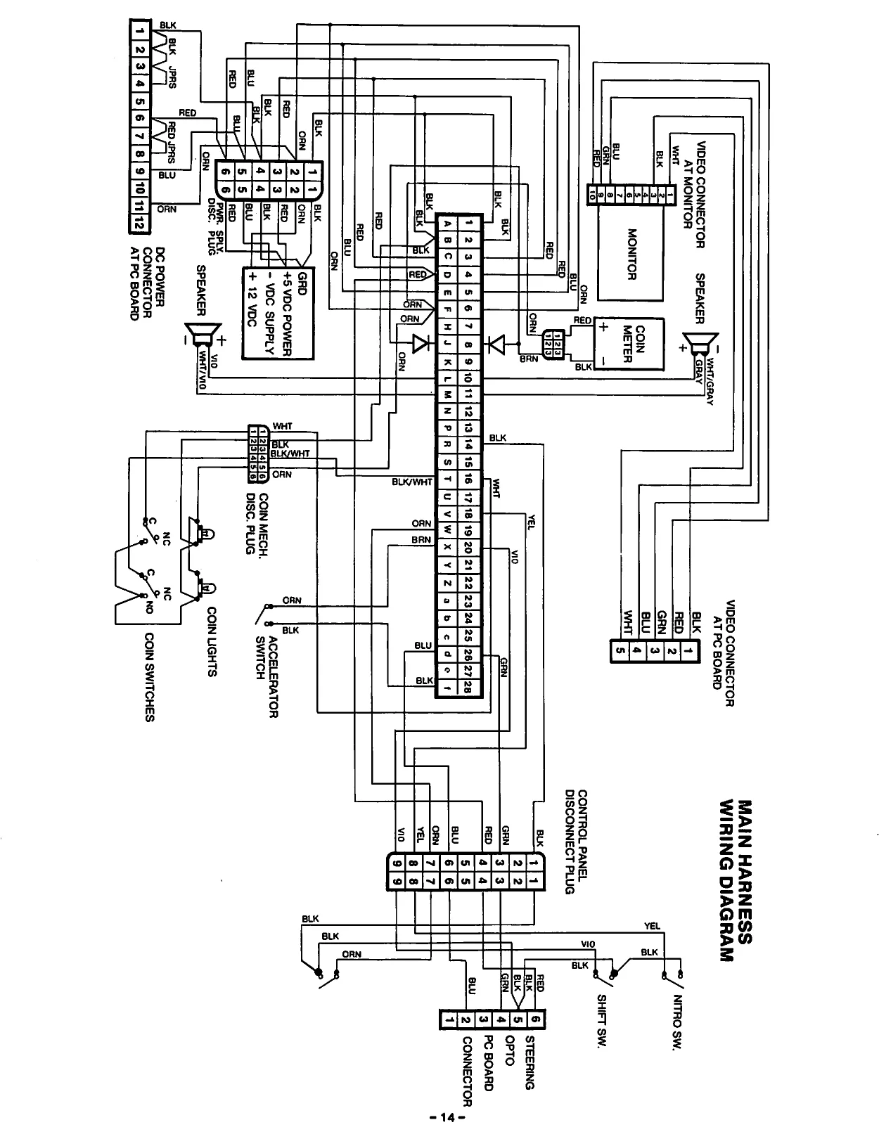
This page is a drawing, shown as the original scan.
AC and GROUND SIDEWALL HARNESS
CONTROL PANEL
ON/OFF SWITCH
GRN
gy Rin
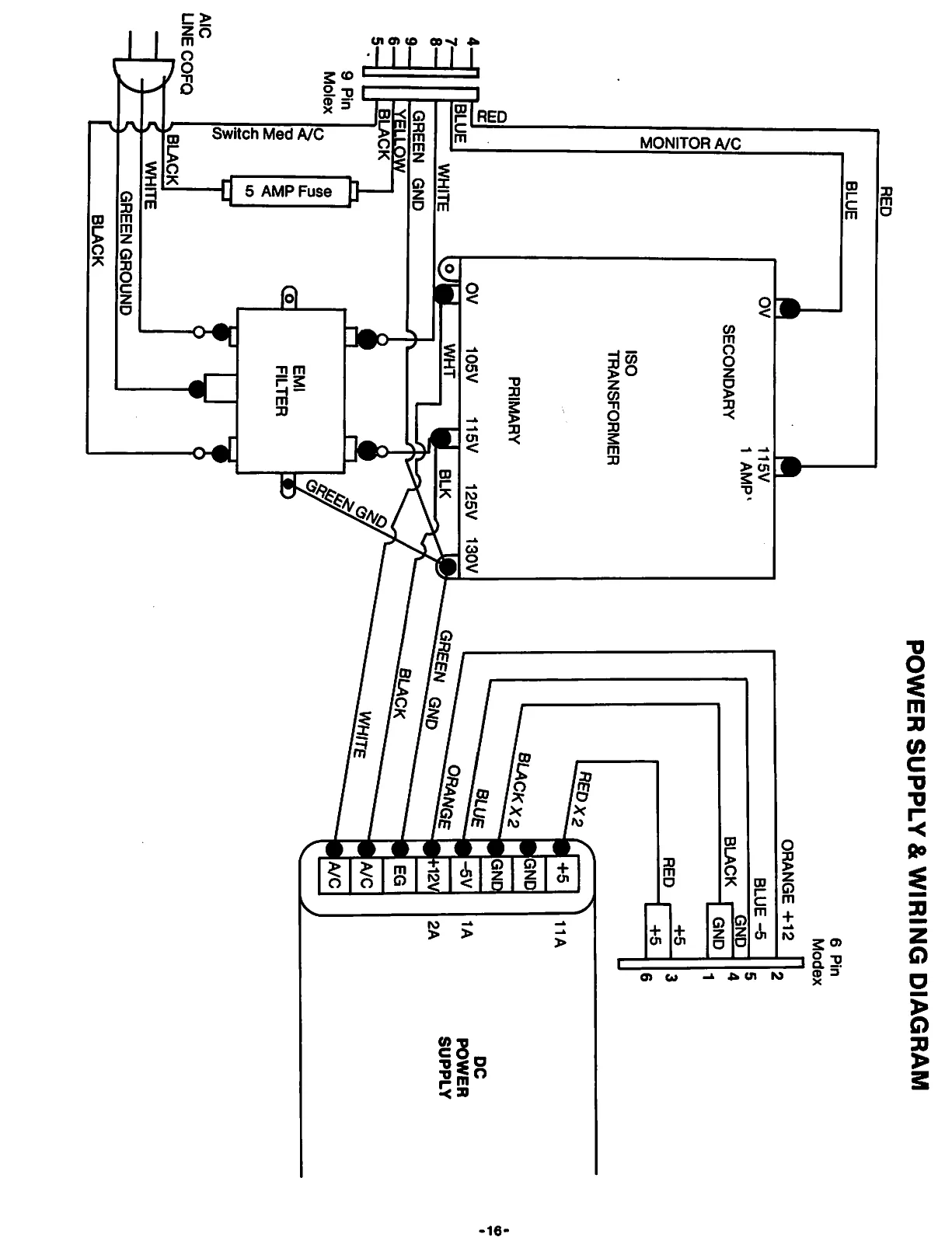
This page is a drawing, shown as the original scan.
This page carries no recoverable text. It is a drawing or a photograph. See the original scan.
SEF HHHE HHH HHH HF HH FHEFHEHHFHH FHF HSHHHHH HHH HHH HHH
LIMITED WARRANTY ate peere ier Veena arse
ROMSTAR ING. (‘Seller’), warrants only to the initial purchaser ofits products thatthe items listed below are free from defects in material and workmanship under normal use and service for the warranty periods specified:
| i | A. Printed Circuit Boards | (60) days |
| B | B. Electronic Components | (80) days |
| H | C. Television Monitor | (80) days |
No other parts of Seller's products are warranted.
Warranty periods are effective from the initial date of shipment from Seller to its authroized distributors.
Seller's sole liability shall be, at its option, to repair or replace products which are returned to Seller during the warranty periods specified, provided:
A. Seller is notified promptly upon discovery by buyer that stated products are defective.
B. Such products are properly packaged and then returned, prepaid to Seller's plant.
This warranty does not apply to any parts damaged during shipping or handling, or due to improper installation or usage, or alteration. Inno event shall Seller be liable for any anticipated profits, loss of profits, loss of use, incidental or consequential damages or any other losses incurred by the customer in connection with the purchase of Romstar Inc. product.
(WARRANTY DISCLAIMER)
EXCEPT AS SPECIFICALLY PROVIDED IN A WRITTEN CONTRACT BETWEEN SELLER AND PURCHASER, THERE ARE NO OTHER WARRANTIES, EXPRESSED OR IMPLIED, INCLUDING ANY IMPLIED WARRANTIES OF MERCHANTABILITY OR FITNESS FOR A PARTICULAR PURPOSE. SHEFHEHHESEH HEHEHE EE SESE FE FE FEF EEE HEHEHE EH EF EH HEHEHE FHEFEHESHH HHH HHH FEF HHH HHFHHEHH HHH HH HHH SHS HHH HHH HHH HH HHH HHHSHHSHHHHSHHHH HH HH HHH
SHEESH EHFHHHEFHEFHHE HSH HHH HH HEFHEFHE HHH HHHHHHHHHH
WARNING
Federal law provides severe civil and criminal penalties for the unauthorized reproduction, distribution, or exhibition of copyrighted audiovisual works and video games.
The Federal Bureau of Investigation investigates allegations of criminal copyright infringement.
COMMENTS:
Your comments will assist Romstar Inc. in improving our product. Your comments are an important part of preparing new games/manuals.
If you have any technical questions regarding our games or are requesting additional information, please contact our Customer Service Department.
Fill in if you wish a reply:
Name
Firm O Distributor
Address O Operator
City State Zip O Other
Area Code Phone
ROMSTAR
ROMSTAR INC. TORRANCE, CALIFORNIA ot. he