Red Baron Sit-Down DP-171-1st-03A
Red Baron (revised hardware) (Atari, 1980) · Drawing Package · 1 pages · original scan
Vector Generator Data Shifter
Vector-Generator Vector-Generator RAM
Address Selector Stack and Program Counter Vector-Generator Data Buffer
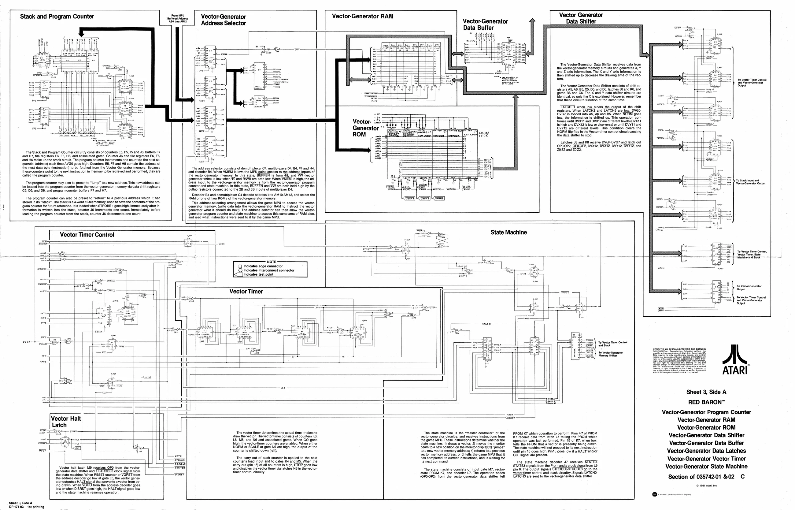
‘The Vector;Generator Data Shifter receives data from
the vector generator memory circuits and generates X, ¥
and Z axis information, The X and Y axis information is then shifted up to decrease the drawing time of the vectors. ‘To Vacor Tine Contot Sinpet The Vector-Generator Data Shifter consists of shift re
sisters AS, AB, B5, C5, DS, and D6, latches J8 and KB, and
‘Gates 86 and C6: The X’and Y data shifter circults are identical, so only the X is explained. However, remember, ‘that these circuits function at the same time. TATCA when tow clare. the output of the sit registers. When LATCH® and ‘are low, DVGO-
YG? Is loaded into AB, AB and BS. When NOFIM goes ishigh and DVX12 is low or vice versa) or until DVY11 and
low, the information is shifted up. This operation con- {inves until DVX11 and DVX12 are different levels (OVX1t
Vector. i's
Ge ce DVYi2 are different levels. This condition clears the
lenerator ao any NORM flipfop in the Vectortimer control circult causing ROM (io the data shifter to stop. Latches J8 and KB receive DVG4-DVG7 and latch out 0P0-0P2, OPOOP2, DVX12, DVXI2, DVY12, DVYT2, and 2022 and Z0Z2. The Stack and Program Counter circuitry consists of counters ES, F5,HS and J6, buffers F7 and H7, file registers E6, F6, H6, and associated gates. Counter J6 and file registers E6, Fb, ‘and H6 make up the stack circuit. The program counter increments one count (to the next se- ‘quontial address) each time AVGO goes high. Counters E5, FS and HS contain the address of the noxt data byte (instruction) to be fetched from the Vector Generator memory. Because ‘these counters point to the next instruction in memory to be retrie called the program counter. ‘The address selector consists of demultiplexer C4, multiplexers D4 £4, Fé and H4, ‘and decoder 84 When VEM is low, tho MPU gain access to the address inputs of the vectorgenerator memory. In this. stat is trom 93, and VW (vector {generator write) is low when 82 and RAWB are both low. When VMEM is high, the ad- ‘reas nput to the vectorgenerator memony a ftom the veclorgeneratr program Counter and state machine. In this stato, BUFFEN and VW are both held Righ By the pullup resistors connected tothe 28 and 38 Inputs of multiplexer Ds Decoder Band demultiplexer C4 decade address bits AMIGAMY2, and select the RAM or one of two ROMS ofthe vectorgenerator memory. ‘his adcressslecting arangement allows the game MPU to access the vector. ‘generator memory, (wrt data into the Yootorgenerator RAM {0 instruct the vector Generator what lt should do next). The address selector can then allow the vector Generator program counter and state machine o access this same area of RAM also, find ead wna instructions were sent toby the game MPU. To Sack input ond ‘The program counter may also be preset to “ump” toa new address. This new address can k out be loaded into the program counter from the vector generator memory via data shift registers (65, DS, and D6, and program-counter buffers F7 and H7.
‘The program counter can also be preset to “retum’ to a previous address which it had stored in its “stack”. The stack is a4word 12-bit memory, used to save the contents of the pro- ‘gram counter for future reference, itis loaded when STROBE 1 goes high. Immediately aftr in formation is written into the stack, counter J6 increments one count. Immediately before loading the program counter from the stack, counter J decrements one count.
Jf, Vector Timer Control State Machine
Fon To Vcr Tir Cont fe} atector dunt = ee
| MALT
voce trea ti - 4 ‘Vator Tn Contol = 3 Sack Saar | Memory Shier Sooeeseeerce Hl [ Bere ceks arene eer 5 | Sirhan pws ovar em he tera
| — 44 Sheet 3, Side A ore 7 : + Saree RED BARON™ ~ i ace Vector-Generator Program Counter Vector Halt ai Vector-Generator RAM
Late " Vector-Generator ROM
: = ‘The vector timer determines the actual time i takes to le machine is the “master controler” of the which operation to perform, Pins 47 of PROM 1
| | | arn | oval | rr oa | cara, | seeegeeror | hey, and aches ratuetons am | Ky ecae sata om latch Lf tng the PROM whch | Vector-Generator Data Shifter | ||
| ‘and | NB and | associated | gates. | When GO goes | ‘game | 32 insructions | determine | whether the | operation was last | performed, Pin 18 of KZ, when low, |
| high, the vectortimer counters are enablod. When either | State machine: 1) draws a vector 2) moves the monitor | fe the PROM at a vector is presently being drawn | Vector-Generator Data Buffer | |||||||
| NOPiM or SCALE at gate NO ar high, the output of the | beam toa new postion on the monitor display; | 3)“jumps" | Te state machine wil not proceed to ts next instruction | |||||||
| ‘counter is shifted down (lft). | to. anew vector memory address; 4) retums to a previous | until pin 15 goes high. Pin5 goes low if a HALT" andlor | Vector-Generator Data Latches |
vector memory address; or 5) tells the game MPU that GQ. signal avo present, ! The cary out of each counter is applied to the next has completed ite current instructions, and is waiting for
‘Sheet 3, Side A (DP-171-03 1st printing Vector halt latch M9 receives OPO from the vector {generator data shifter and a STROBES clock signal from the state machine. When RESET counter or ‘trom the address decoder go low at gate L5, the vector generator outputs a HALT signal that prevents a vector from being drawn, When VGGO from the address decoder goes ow or when DISRST goes high, he HALT signal goes low ‘and the state machine resumes operation. ‘counters load input and to gates Ké and MS. When the Carry out (pin 15) ofall counters is high, ‘and disables the vector timer vi timer contol cireuity goes low hes NBin the vector its next command,
The state machine consists of input gate M7, vector state PROM K7, and decoder L7. The operation codes (©P0.0P2) trom the vectorgenerator data shifter tell The state machine decoder J7 recsives. STATED: STATES signals om the Pron anda clock signal om (3 pit 8. The ouput signals STROBED STROBES go to the {ectortimor contol and stack crculty. Signals CATCH. ESSA wont to the vectorgonertor Gta ster Vector-Generator Vector Timer Vector-Generator State Machine
Section of 035742-01 &02 C
© 1061 Aa te