Killer Instinct 2 Rom Kit Manual (16-45064-101 Feb 1996)
Killer Instinct 2 (Rare / Nintendo (Midway license), 1996) · Kit Manual · 57 pages · 26 sections · original scan
FEBRUARY 1996 MIDWAY 16-45064-101
KILLER INSTINCT 2 ROM KIT MANUAL
MANUAL INCLUDES Installation & Operation * Testing & Problem Diagnosis
Parts Information ° Wiring Diagrams
1! WARNING !!
IMPORTANT NOTICE
PLEASE READ
DO NOT CONNECT THE KILLER
INSTINCT 2 DISK DRIVE RIBBON CABLE
TO THE KILLER INSTINCT 1 CPU
BOARD. THE KILLER INSTINCT 1 CPU
ASSEMBLY WILL CORRUPT THE DATA
STORED IN THE KILLER INSTINCT 2
HARD DISK. THIS WILL RENDER THE
KILLER INSTINCT 2 HARD DISK NON-
FUNCTIONAL.
HARD DRIVE HANDLING GUIDELINES
Hard drives are especially sensitive to rough handling and electrostatic discharge (ESD). To avoid these hazards, adhere to the following guidelines:
ELECTROSTATIC DISCHARGE (ESD) Keep the end of the drive cable in an anti-static bag until you are ready to install it in your system. Do not put any other objects inside the anti-static bag with the end of the drive cable.
HANDLING
Do not put anything on top of the drive - especially another drive. Do not drop a disk drive. Some drives can be damaged by being dropped from an inch above a hard surface.
Be sure to handle the hard drive with care when setting it down. Do not set the drive on its edge.
INSTALLING
When installing the drive, remove the cable from the anti-static bag. Turn off the power before connecting the drive to the system. Do not connect the drive to the CPU board, or disconnect the drive from the CPU board, while power is on. BE VERY CAREFUL TO ALIGN THE DRIVE CABLE CORRECTLY WITH THE CPU CONNECTOR. Installing a the hard drive cable incorrectly will ruin the drive!
STORING, PACKING, AND TRANSPORTING DRIVES If you are using the single pack carton, do not pack more than one drive per carton. Pack the end of the drive cable in an anti-static bag. Then, put the hard drive in an approved shipping container. (p/n 08-7981) Do not throw, drop, puncture, or walk on shipping boxes.
Information current at time of release.
Fill out and mail in game Registration card. Be sure to include the game serial number. For your records, write the game serial number in the manual.
MIDWAY Manufacturing Company reserves the rights to make modifications and improvements to its products. The specifications and parts identified in this manual are subject to change without notice.
TABLE OF CONTENTS Section One - Operation Safety Notices... Installation Procedure.
Cabinet and Control Panel Modifications.. Electronic Rack Modifications, Servicing..... Game Features.. Starting-up. 1-10 Player Controls. 1-10 Control Panel Diagram. 1-10 Game Operation... 1-11 Control Switche: 1-11 Control Switch Location Diagra 1-11 Menu System Operation. 1-12 Operation... 1-12 Main Menu. 1-12 Diagnostic Test. 1-13 Switch Test. DIP Switch Table and Tes! CPU and Sound Test... Monitor Patterns and Burn-in Test.
Game Audits. Game Adjustmen Standard Pricing Table..
Section Two - Parts Information Cabinet - View Cabinet - View Cabinet Rear Vie Rear Door Parts & Coin Door Parts.. Control Panel & Housing Parts.. Other Necessary Parts........ CPU Board (Before Conversion to KILLER INSTINCT 2). CPU Board (After Conversion to KILLER INSTINCT i Power Supply... 7 Section Three - Cabinet Wiring JAMMA Chart... Interboard Wiring. 3-3 Power Wiring and 3-4 Cabinet Wiring Diagram.............+« Electronic Rack Assembly (Before Conversion to KILLER INSTINCT 2: Electronic Rack Assembly (After Conversion to KILLER INSTINCT 2).. Killer Instinct 2™ © 1994, 1995 Nintendo/Rare ™Trademark of Nintendo Developed by Rare Manufactured and sold by MIDWAY Manufacturing Company under license. Nintendo® and Killer instinct 2 ™ are trademarks of Nintendo Co., Ltd. The Rareware Logo™ is a trademark of Rare Ltd.
iv
ROM KIT
SECTION
ONE Ne
SAFETY NOTICES
The following safety Instructions apply to all game operators and service personnel. Specific warnings and cautions will be found throughout this manual where they apply. We recommend that you read this page before preparing your game for play.
ZN CAUTION HARD DRIVE. The end of the hard drive cable must be packed In an anti-static bag. The disk drive assembly must be packed In an approved shipping container (p/n 08-7981) in order to be sent in for repair or replacement.
TRANSPORTING GAME: This game contains fragile electronic devices. Do not move this game with power on. Properly secure the game before transport. Avoid rough handling.
AC POWER CONNECTION. Before connecting the game to an AC power source, verify the Voltage Selection Chart jumper wires are installed correctly for the line voltage in your area. For details refer to Section 3 of this manual.
ISOLATION TRANSFORMER. The monitor does not require an isolation transformer. However, when servicing the monitor on a test bench you must isolate the monitor from line voltage with an Isolation transformer.
ELECTRO STATIC DISCHARGE. This game contains devices that are sensitive to static electricity. Properly ground yourself before handling any of the electronic devices in this game. Prepare an anti-static work area before attempting to remove or repair any of the electronic devices in this game.
PROPERLY GROUND THE GAME. To avoid electrical shocks, do not plug in the game until it has been inspected and properly grounded. MIDWAY games should only be plugged into a grounded 3-wire outlet. NOTE: The control panel is removable. Be sure that the ground braid is securely attached to the control panel after servicing.
DISCONNECT POWER DURING REPAIRS. To avoid electrical shock, disconnect the game from the AC power source before removing or repairing any part of the game.
USE THE PROPER FUSES. To avoid electrical shock, replacement fuses must match the original fuse in fuse type, voltage rating, and current rating.
HANDLE FLUORESCENT TUBE AND CRT WITH CARE. If you drop a fluorescent tube or CRT and it breaks, it will implode! Shattered glass can fly eight feet or more from the implosion.
ATTENTION PROPERLY ATTACH ALL CONNECTORS. Be sure that the connectors on each printed circuit board (PCB) are properly connected. If they do not slip on easily, do not force them. A reversed connector may damage your game and void the warranty. All connectors are keyed to fit specific pins on each board. CY
NOTICE - FCC COMPLIANCE
|. THIS KIT WAS TESTED IN A KILLER INSTINCT VIDEO CABINET AND FOUND
TO COMPLY WITH FCC PART 15 CLASS A REQUIREMENTS.
I. INSTALLATION OF THIS _KIT_INTO_ANY OTHER PRODUCT DOES NOT
GUARANTEE COMPLIANCE WITH FCC REQUIREMENTS. YOU ARE SOLELY
RESPONSIBLE, AND MIDWAY WILL HAVE NO RESPONSIBILITY FOR FCC
COMPLIANCE FOR INSTALLATIONS IN OTHER PRODUCTS. THE FCC
COMPLIANCE STICKER SHOULD NOT BE INSTALLED ON THE CONVERTED
PRODUCT UNTIL FCC COMPLIANCE IS VERIFIED.
EPILEPSY WARNING
A very small portion of the population has a condition which may cause them to experience epileptic seizures or have momentary loss of consciousness when viewing certain kinds of flashing lights or patterns that are present in our dally environment. These persons may experience seizures while watching some kinds of television pictures or playing certain video games. People who have not had any previous seizures may nonetheless have an undetected eplleptic condition.
If you or anyone In your family has experlenced symptoms linked to an epileptic condition (e.g. seizures or loss of awareness), Immediately consult your physician before using any video games.
We recommend that parents observe thelr children while they play video games. If you or your child experience the following symptoms: dizziness, altered vision, eye or muscle twitching, involuntary movements, loss of awareness, disorientation, or convulsions. DISCONTINUE USE IMMEDIATELY and consult your physician.
INSTALLATION PROCEDURE The hard disk drive and IC chips included in this kit are fragile and static sensitive. Prepare an anti-static work area before removing them from their protective anti-static packaging. Avoid rough handling.
PARTS LIST The following is a list of parts included in the KILLER INSTINCT 2 ROM Kit.
Part Number Description A-20337 Programmed Hard Disk Drive A-20348 Disk Drive Add-on Board A-20356 Disk Drive Mounting Spacers A-5343-45064-1 U98 EPROM A-5343-40064-2 U10 EPROM A-5343-40064-3 U11 EPROM A-5343-40064-4 U12 EPROM A-5343-40064-5 U13 EPROM A-5343-40064-6 U33 EPROM A-5343-40064-7 U34 EPROM A-5343-40064-8 U35 EPROM A-5343-40064-9 U36 EPROM anne ec et eee teen eee tne
08-7981.1 Disk Drive Shipping Container 16-9478.2 Registration Card 16-10076 Disk Drive Handling Sheet 16-10080 Hard Disk Mounting Instructions 16-10081 ROM Kit Installation Instructions 16-45064-101 ROM Kit Game Manual 31-2380-1 Kit Marquee 31-2381-1 Player Moves Instruction Card 31-2381-2 Game Operation Instruction Card 31-2386 Control Panel Wallpaper Decal 31-2387 Control Panel Add-ons Decal
CABINET AND CONTROL PANEL MODIFICATIONS
- Turn off and unplug the game. Remove the rear door. Open the coin door and the control panel.
- Unscrew the five hex-head screws from the black marquee retaining strip on the top of the cabinet. Remove the KILLER INSTINCT marquee. Trim the KILLER INSTINCT 2 marquee to the KILLER INSTINCT marquee size and install in its place. Replace the marquee retaining strip.
- Unscrew the five hex-head screws from the black metal strip at the bottom of the viewing glass. Grasp the viewing glass from the bottom and carefully slide it out of the side grooves and lift it clear of the cabinet. Be sure to clean the CRT and the viewing glass.
- Apply the player moves instruction decal to the bottom front of the monitor bezel. And apply the game play instruction decals to the top front of the monitor bezel. Be sure the decals do not obstruct the CRT. Replace the viewing glass.
5 Remove the control panel buttons and joysticks and remove the KILLER INSTINCT vinyl control panel covering and artwork.
1-4 la
5a) Label each switch as it is removed from the control panel. This makes reinstallation much easier. Remove the switch from the push-button by pulling the large prong away from the switch, then pull the switch off of the housing. Unscrew the nut from the housing. Slide the push button out of the control panel and set It aside. Carefully, let the switch hang from contro! panel cable.
5b) To remove the joysticks, first remove the “E*-ring and slide the joystick shaft and the plastic ting off the joystick base. Be sure that the bushings remain in the base. Be sure to store the joystick shaft, plastic ring, and “E”-ring, together.
5c) Lift the KILLER INSTINCT control panel cover off of the contro! panel. Clean any glue reside. Be sure the surface of the control panel is smooth.
Carefully remove the backing on the KILLER INSTINCT 2 wallpaper decal overlay. Place the overlay on the top of the control panel. Prevent air bubbles from getting under the overlay.
After the overlay is secure, use a razor knife to trim any excess and to cut holes for the contro! panel buttons and joysticks. Position the add-on decals next to the appropriate hole locations.
Replace the control panel buttons and the joysticks.
Start ce) fe) High Attack High Attack Quick Medium Fierce Quick Medium Fierce © O°0O M “© 00 0o°0 Quick Medium Fierce Quick Medium Fierce Low Attack Low Attack
CONTROL PANEL LAYOUT
ELECTRONIC RACK MODIFICATIONS The hard disk drive and IC chips included in this kit are fragile and static sensitive, Prepare an anti-static work area before removing them from their protective anti-static packaging. Avoid rough handling.
- Unplug the EPROMS shown in the drawing below, from the KILLER INSTINCT CPU board. Carefully, remove the KILLER INSTINCT 2 EPROMS from their anti-static container. Plug each one Of the chips into the proper socket. Be sure to match the notch on the chip with the notch outlined in white on the board.
KILLER INSTINCT CPU board Pin 1 Location Unplug the shaded EPROMS. NOTCH PIN, 4
- Unplug the disk drive connector from J6 on the CPU board. Remove the screws holding the disk drive mounting bracket to the rack and take the disk drive and mounting bracket out of the game. Also remove the ferrite bead.
- From the component side of the board, push two small white plastic spacers into the mounting holes on the Add-on board. Plug J1 from the Add-on board into J6 of the CPU board so that the right
angle connector, J2, extends out over the top of the CPU board. Screw the Add-on board to the rack,
- Insert one red spacer into each of the four holes in the KILLER INSTINCT 2 disk drive enclosure. Place the disk drive next to the CPU board. Be sure that the connector on the disk drive cable can reach J2 (the right angle connector) on the Add-on board. Use the hex-head screws in the spacers and fasten the disk drive to the rack. Plug the ribbon cable connector from the disk drive into J2 of the Add-on board. See drawings below.
Electronic Rack Before Modification Electronic Rack After Modification
- Once the cabinet, control panel and electronic rack modification are complete, close and latch the control panel. Close and lock the coin door. Replace the rear cabinet door. Plug the game in and turn it on.
- Verify proper game operation via internal game diagnostics. Configure the coinages and other game related options as necessary.
SERVICING
@ Servicing the Control Panel Switch off power to the game and open the coin door. The control panel is held in place by two latches (located inside the cabinet) which provide constant pressure on the strikes. To release the latches, reach through the coin door opening toward the right and left sides of the cabinet. Do not reach straight back through the coin door or you could damage the monitor contro! board. Lift the latch hc and unhook the wire fasteners. Grip the joysticks and carefully tilt the contro! panel back on Its hinge.
To return the contro! panel to its normal position, carefully lean it forward until it rests on the cabinet. Be careful not to tet the control panel slam down onto the cabinet, or to pinch any wires. Always reclasp the latches.
@ Removal of the Viewing Glass Switch off power to the game and open the control panel. Remove the five hex-head screws and the black metal strip at the bottom of the viewing glass. Carefully, slide the glass from the side grooves and lift it clear of the cabinet.
@ Removal of the Monitor Bezel Switch off power to the game. Open the contro! panel and remove the viewing glass. Lift the bezel off of the monitor.
@ Monitor Replacement We recommend that you read the SAFETY NOTICES section thoroughly before beginning this procedure. Switch off power to the game. Remove the viewing glass and the monitor bezel. Completely disconnect the monitor from all of its cabling. Remove the four flange nuts securing the monitor's mounting flanges to its mounting panel. Pull the monitor carefully from the cabinet.
A\ CAUTION The monitor does not require an isolation transformer. However, when servicing the monitor on a test bench, YOU MUST ISOLATE THE MONITOR FROM LINE VOLTAGE WITH AN ISOLATION TRANSFORMER. THE MONITOR IS HEAVY. BE SURE IT IS FIRMLY SUPPORTED IF IT MUST BE REMOVED FROM THE CABINET.
@ Hard Drive Replacement REMEMBER: HARD DRIVES ARE FRAGILE Use an anti-static bag and approved shipping container (p/n 08-7981.1) to return the hard drive to your distributor. Switch off power to the game and open the rear door. Unplug the ribbon cable from the Add-on board. Unscrew the four hex head screws in the spacers. Remove the spacers from the enclosure and set them aside. Remove the hard drive and enclosure assembly, (see Hard Drive Handling Guidelines in the front of this manual). Place the spacers - one in each four corner holes - in the new hard drive enclosure. Place the enclosure assembly, with the ribbon cable facing the top of the game, on the wood chassis. Use the hex head screws to fasten the assembly in place. Carefully plug the ribbon cable into the Add-on board. .
@ Removal of the Marquee Switch off power to the game. Remove the hex-head screws from the black marquee retaining strip located on top of the header. Remove the strip and carefully lift the marquee and the marquee glass from the top of the header. Store the marquee carefully to prevent damage.
@ Removal of the Fluorescent Light Assembly Switch off power to the game. Remove the marquee glass and the marquee. The fluorescent bulb is now accessible for replacement. Remove the plastic lamp locks. Grasp the bulb, give it a quarter turn, and remove it from its socket. Carefully, place a new bulb Into the socket, and turn to reinstall.
To remove the entire light fixture, disconnect the fluorescent light assembly from its power cable. Remove the screws that hold the assembly to the cabinet then lift out the assembly.
1! WARNING !! If you drop a fluorescent tube and It breaks, It will implode! Use care in handling.
@ Removal of the Speakers Switch off power to the game. Remove the marquee and the marquee glass. The speakers come out from the front of the cabinet. Be sure to disconnect the cabling and remove the nuts on the mounting screws before attempting to remove the speakers from the enclosure. Carefully, reinstall the seals upon completing any task in the speaker enclosure.
@ Volume Control, Begin Test Switch, and Service Credit Switch Open the coin door. The game's volume control and diagnostic push-button switches are located on a small bracket on the coin door. The volume is controlled by the two center buttons. Press the Volume Up or the Volume Down button until the desired sound level Is reached. The Begin Test switch, on the right, activates the game's menu system. The Service Credit switch, on the left, allows Credits to be allotted for service testing without affecting the game's bookkeeping total.
GAME FEATURES STARTING UP Switch on power to the game. The game runs through a start-up routine.
Insert the desired amount of coins, bills or tokens. Select which player receives the credit by pressing the appropriate Start button.
PLAYER CONTROLS « Start Button Each player has a Start button. The Start buttons allow one or two players to begin or continue play.
¢ Joysticks Each player has a joystick which he uses to control an on-screen character. The player can make the on-screen character move, jump or duck.
¢ High Attack An attack that originates above the waist, such as a punch.
@ Low Attack An attack that originates below the waist, such as a kick.
@ Quick A ‘quick’ attack is a short range, short duration attack that inflicts little damage to an opponent.
@ Medium A “medium” attack is a moderate range, moderate duration attack that inflicts some damage to an opponent.
@ Fierce A “fierce" attack Is a long range, long duration attack that inflicts much damage to an opponent.
| a | Quick | Medium | Fierce | “ume | Quick | Medium | Fierce |
| Oo | O9O | © | O9O |
Move Move fe) fe) Move Move © © ©
| Duck | Quick | Medium | Fierce | Duck | Quick | Medium | Fierce |
Low Attack Low Attack
CONTROL PANEL
GAME OPERATION The KILLER INSTINCT/KILLER INSTINCT 2 game Control switches are located on a bracket, inside the coin door.
CONTROL SWITCHES
o Slam Tilt Switch The Slam Tilt switch prevents pounding for free games.
Volume Down/Volume Up Buttons The Volume Down and Volume Up push-button switches increase or decrease the volume level of the music and speech. The volume level can be adjusted during the Attract Mode or during menu system operation. For greater profits, set your game's volume level at a nice loud setting.
Begin Test Button The Begin Test push-button switch enters the game's menu system. Press the Begin Test switch to access any of the menu system functions.
Service Credit Button The Service Credit push-button switch is a special feature switch that allots credit without affecting the game's bookkeeping total.
‘These buttons can be used instead of the contro! panel buttons when operating the Menu System. The Up and Down buttons move the cursor, and the Enter and Escape buttons open and close the menus.
CONTROL SWITCH LOCATIONS
MENU SYSTEM OPERATION
OPERATION All game audits, adjustments and diagnostics are options of the Main Menu. Each option, in turn, has its own menu that lists several choices which you may act upon as desired.
Press the Begin Test switch on the coin door to open the Main Menu (shown below). Game adjustments, bookkeeping and diagnostics are all accessible from this menu.
Use any joystick to move the cursor up and down the menu screen. Notice that the options are highlighted in sequence. Press any action button (Quick. Medium, Fierce), on the contro! panel to open a highlighted option.
To exit the Main Menu and retum to the Attract Mode, use any joystick to select EXIT TO GAME OVER and press any action button.
DIAGNOSTIC TESTS Use any Joystick to select the Diagnostic Menu and any action button to open it. Then, use any joystick to move the cursor up and down the menu and any action button to open a highlighted option.
To exit the Diagnostic Menu, use any joystick to select RETURN TO MAIN MENU and press any action button.
Switch Test The Switch Test allows the operator to test the switches on the control panel and in the coin door.
Use any joystick to highlight the Switch Test and any action button to begin the test. During the Switch Test the top of the screen shows the control panel switches while the bottom of the screen shows the coin door switches. Press a control panel or coin door switch and the switch location on the screen lights. Release the switch and the screen returns to normal.
To exit the Switch Test, press both Start buttons together.
PRESS BOTH START BUTTONS TO EXIT O O PI START P2 START 000 A000 0600 9dd0 O COINS COIN4 SERVICE = SLAM TEST O O O90 BILL vOL- VOL+ — 000R
SWITCH TEST SCREEN
DIP Switch Test The DIP Switch Test allows the operator to check or change the position of the DIP Switches on the CPU,
Use any joystick to select the DIP Switch Test. Press any action button to access the DIP Switch Setting Tables. The screen displays the current settings. To change a setting, slide the switch to the desired Position. Check the screen to verify the new setting. in some cases, setting a function to OFF actually enables the function. For example, setting Coinage to Off enables DIP Switch Coinage.
Press any button to return to the Diagnostic Menu.
High Blood Level Med. Blood Level Low Blood Level No Blood Attract Sounds Attract Sounds On No Attract Sounds Finishing Moves Finishing Moves No Finishing Moves Violence Warning Display Violence Waming No Violence Warning
DIP Switch CMOS Coin Settings USA1 Ger. 1 USA2 Ger. 2 USA3 Ger. 3 Ger. 4 Ger. ECA Ger. 5 NU Free Pla)
*indicates factory setting.
1-14
CPU Test ww) The CPU Board Test allows the operator to check the main CPU board components, Including the RAM and EPROMS. Select the CPU Board Test with any joystick. Press any action button to start the test. A “rug” pattern appears on the screen. When the “rug” pattern ends, either Test O.K. or Test Failed appears on the screen. The game returns to the Diagnostic Menu automatically.
Sound Test . This test allows the operator to listen to some of the sounds this game is capable of producing. Use any joystick to select the test, then press any action button to open the menu. The screen displays two test options. Use any joystick to select an option and any action button to begin the test.
Nar GENERAL TEST analyzes the sound circuitry. The screen shows a list of error codes. A successful test causes a single "tone" to sound. Detection of a fault causes a series of tones or no tone at all to sound. Press any action button to return to the Sound Test Menu.
PLAY SOUNDS tests synthesized and digitized sounds from the CPU/Sound board. Advance to the next sound with any action button. Use any joystick to end the test.
Select RETURN TO MAIN MENU or BACK TO DIAGNOSTIC MENU and press any action button.
Monitor Patterns The Monitor Patterns Test provides a menu for testing the monitor.
Select the test with any joystick. Press any action button to open the test menu. Once the menu is open, use any joystick to select an option, and any button to begin it. Press any action button again to return to the Monitor Patterns Menu.
The RED, GREEN and BLUE SCREEN tests fill the screen with either red, green or blue. Press any action button to return to the Monitor Patterns Menu.
The COLOR BARS test fills the screen with 15 shades of colors to help with red, green and blue level! adjustments. Each color should appear sharp and clear. Adjust the contrast and brightness levels until the 15 color bars are visible. Press any action button to return to the Monitor Patterns Menu.
The CROSSHATCH PATTERNS test fills the screen with a grid and a series of dots. The grid and the dots should be clear. The dots should be round. Press any action button to return to the Monitor Patterns Menu.
If any of the tests show a need for adjustment, use the proper knobs on the Monitor Controls board.
To exit this test, use any joystick to select RETURN TO MAIN MENU or BACK TO DIAGNOSTIC MENU, then press any action button.
1-16
Check Disk This test checks the hard disk drive. NOTE: This test may take several minutes to complete.
Use either joystick to select the test, then press any button to activate it. Press any button to return to the Diagnostic Menu.
CHECK DISK SCREEN
Burn-in Test The Burn-in Test continually repeats the CPU Board Test. Use this test to find intermittent CPU Board Problems. The Audit Table specifies the number of Burn-in cycles that have been successfully completed.
Use any joystick to select the test, then press any action button to activate it. When the Bum-in Test detects an error the test stops and an error message is displayed on the screen.
To exit this test, switch the game off, then on again.
COIN BOOKKEEPING The Coin Bookkeeping Table records the coin box totals and the game play counters.
Use any joystick to select the Coin Bookkeeping Menu, then press any action button to open it.
eae He
Sram tal
To exit Coin Bookkeeping, use any Joystick to select RETURN TO MAIN MENU and press any action button.
GAME AUDITS Use any joystick to select the Game Audits Menu, then press any action button to open it. Page through the available audits by selecting NEXT AUDIT PAGE or LAST AUDIT PAGE. Select RETURN TO MAIN MENU and press any action button to exit Game Audits.
Game audits cannot be set. They can only be cleared.
1-19
Game Audits Continued...
i
=
i i
i
reat 0% ae
j i a)
1-20 -~
Game Audits Continued...
o TaN ee 3
i i
TE ee a ip on = ea et a al Fane
:
1-21
Game Audits Continued...
i i i
eis
ma
Hit ut ua
iE
ie é ae i
ie
x : ma f
if
fi
: : ae
Ney
i i bi HH aL ti ti alt fe FO
1-22
Game Audits Continued...
= ss Ey
Bs aga
ww)
| :
1-23
GAME ADJUSTMENTS The Game Adjustments allow the operator to customize the game.
Use any joystick to select the Game Adjustments Menu. Press any action button to open the menu.
The Game Adjustments Menu offers several options. Each option has several choices. Use any joystick to select an option, then press any action button to open the option. The next menu screen provides a setting value. Use any joystick to change the setting value and press any action button to lock it In.
To exit the Adjustments Menu, use any joystick to select RETURN TO MAIN MENU, and press any action button.
Game Adjustments Standard Pricing Standard pricing allow the operator to choose any of the “standard” selections from the Standard Pricing Table. See page 1-26
Modify the setting value with either joystick. Press any button to lock in the new value and return to the Adjustments Menu.
Custom Pricing Custom pricing allows the operator to install pricing other than that of the Standard Pricing Table. Custom pricing also allows the operator to select the maximum amount of credits per game, the amount of credits required to start a game, and the amount of credits required to continue a game. To use Custom Pricing, the Coinage DIP Switch must be set to ON (CMOS - switch #1 of DIP Switch bank #2). See page 1-14 for DIP Switch Table. See page 1-27 for Custom Pricing Table.
Modify the setting value with either joystick. Press any button to lock in a new value and return to the Adjustment Menu.
1-24
Game Adjustments Continued...
Free Play This option selects free play. The setting choices for this adjustment are: -No
- Yes
- Factory Setting: No
Computer Difficulty This option determines how tough the computer opponents are. The setting choices for this adjustment are:
- (1) Extra Easy
- (2) Easy
- (3) Medium
- (4) Hard
- (5) Extra Hard + Factory Setting: Medium
Winning Streak This option determines the number of games that must be played before the high scores automatically reset to factory settings. The setting choices for this adjustment are:
- No Reset
- 5000 games
- 10,000 games
- 15,000 games ~ Factory Setting: No Reset
1-25
STANDARD PRICING TABLE
(2 to Start, 2 to Continue) (2 to Start, 1 to Continue) (1 to Start, 1 to Continue) (1 to Start, 1 to Continue) (2 to Start, 1 to Continue) (1 to Start, 1 to Continue) (1 to Start, 1 to Continue) (1 to Start, 1 to Continue) (B to Start, 2 to Continue) (3 to Start, 3 to Continue)
1/1DM, 7/5DM 1/1DM, 8/5DM 1/1DM, 5/5DM 1/1DM, 6/5DM 1/1DM, 2/2DM, 6/5DM. France 1 205F, SOF France 2 2I5F, 4/10F France 3 V5F, 3/10F France 4 1S5F, 2/10F France 5 Q/SF, S/10F, 11/2 x 10F France 6 2/5F, 4/10F, 9/2 x 10F France 7 SF, Y/10F, 7/2 x 10F France 8 SF, 2/10F, 5/2 x 10F France 9 V3 x 1F, 25F France 10 V2 x 1F, SSF France 11 13 x 1F, 2/5F, 5/2 x SF France 12 V2 x 1F, YF, 7/2 x SF rance ECA 2/5F, 5/2 Fi
Swiss 1 WIF, G/5F Swiss 2 VIF, 7/5F Swiss 3 IAF, SF [italy T1750 ire
fet (aes ee Te
| Australia 2 | 1/5 x 20¢, 1/$1.00 | $1 | ||||
| p | 2/100 | yen | 100 | yen | 100 | yen |
V30P, 2/50P, 4/21 1/100 peseta, 6/500 peseta 100 peseta 1/100 peseta, 5/500 peseta 100 peseta
g &
| tia 1 | 15 schilling, 2/10 schilling | ese | | 10 schilling |
| Austria 2 | 4/2 x5 schilling, 3/2 x 10 schilling | 9 | 10 schilling |
20F Belgium
SOF [Sweden | 1xtkrona, 2S krona ft rona bi New Zealand 2
| [Netherlands | | W1HF.@2SHF | SSC | THI | [SHR | {PT |
| rFiniand | | Wimarkka | dark | tmarkka | [TT | |
| [Norway| Waxikrone, Wexikrone | =~ | tkrone | | tkrone | [TT | |
| [Denmark | | V2x1krone, 9Skrone, 72xekrone | | tkrone | [Skrone | [TT | |
| Antiles | | | 25e.4/ guider | ee | guider | PT |
| [ Hungary | | 1/2. x10 forint, 92x20 forint | [20forint | fd |
1-26
CUSTOM PRICING
Coins inserted accumulate units. This adjustment specifies the number of units given for each coin in the fourth chute (see “Units/Credit").
Coins inserted accumulate units. This adjustment specifies the number of units given for each bill validated (see “Units/Credits’).
This Is the number of coin units required to buy one credit.
There is one bonus credit awarded after this many coin units have accumulated.
This Is the minimum number of units required before any credits are awarded.
Each player needs this many credits to begin a game.
Each player needs this many credits to continue a game.
This is the limit for the credit counter. Additional coins inserted will be lost (factory setting: 50).
1-27
UTILITIES The Utilities Menu allows the operator to clear the game's bookkeeping memory.
Use any joystick to select the Utilities Menu, then press any action button. Use any joystick to select a utility. Press any action button to activate the selection.
Once the selection is made, a dialogue box appears, and the operator can choose to reset the utility.
For example:
CLEAR COIN COUNTERS? ARE YOU SURE?
Use any joystick to choose a setting value. Press any action button to lock in the new setting value.
To exit the Utilities Menu, use any joystick to select RETURN TO MAIN MENU, then press any action button.
1-28
VOLUME ADJUST The Volume Adjust feature allows the operator to determine the sound and music level of the game.
The volume level can be adjusted from either the Attract Mode or the Menu System. Press the Volume Up button to raise the volume level and the Volume Down button to lower the volume level. Any joystick can also be used to raise or lower the volume level. The current volume level is shown with a red bar.
Press any action button to return to the Main Menu.
VOLUME ADJUST PRESS ANY BUTTON TO EXIT
MAX.
USE JOYSTICK OR VOLUME BUTTONS TO ADJUST VOLUME.
1-29
ES TROUBLESHOOTING
PROBLEM 1)
2)
3)
4)
5)
6)
8) No picture or distorted picture.
Turn game On and nothing happens.
No sound.
No general illumination.
Press Start button and nothing happens.
No credit given for number of coins inserted.
Too many credits for number of coins inserted.
Game stays in test mode. POSSIBLE SOLUTION 1)
2)
3)
4)
5)
6)
8)
1-30 Check for faulty video board or monitor. Check for disconnected video signal cable.
Check line fuse. Check for +5Vdc at pins C, D, 3 and 4 of the JAMMA connector.
Check the speaker and the speaker connection to pin L and 10 on the JAMMA connector. Check volume control setting. Check for +12Vdce at pins F and 6 on the JAMMA connector. Check for -5Vdc at pins E and 5 on the JAMMA connector.
Check the 1A, S.B. fuse in the A.C. power pack assembly.
Check for open wires between the button and the CPU board. Check for contamination on CPU board pins or the Start button switch blade contacts. Check for proper ground.
Check DIP switch coin settings. Check for contamination on the coin switch contacts. Check for an open wire between Coin Switch 1 and pin 16 on the JAMMA connector or Coin Switch 2 and pin T of the JAMMA connector.
Check the game pricing settings. Check for a short between pins T & 16 on the JAMMA connector.
Check that the switch #1 of DIP switch bank #2 is set to off.
NOTES
1-32
ROM KIT
SECTION
Two YY
PARTS
cent Lomp Assembly
Fluoresc A-15890 KILLER INSTINCT
CABINET FRONT - VIEW 1
Bezel
03-8497
grip Nut 1/4~20 Floni 4420-01141-00
; B
EM En Ba * 2 =H Ey ‘2 ee gs ie TT se 3¥
MS 8-32x3/8 PL-HWH 4008-01113-05
2-2
KILLER INSTINCT CABINET FRONT - VIEW 2
Marquee Retainer 03-8252-2 Screw H-F #8x11/16 PL—-HWH 4608-01081-11 \ Chonnel Glass Edge 03-9373-1
Blank Mgrquee Glass 08-7456-4
Chonnel Glass Edge 03-9373-1 Speoker 8 ohm 5555-13961-00
Nut 6-32 KEPS 4406-01128-00 Cabinet Assembly A-19178-40047
, Nut 8-32 KEPS On/Off Switch 4408-01128-00
Screw SSS 6-32x1-1/2 4506-01106-24B
Speoker Grille 01-11859
Screw J8x5/8 TRX-TR 4108-01 193-108
Bolt 8—32x1-1/4CB 4308-01123-20B
Coin Door-USA 09-50000-33
A-19584 Blank Coin Door w/Lock (see detailed diagrom) 09-41000
01~-9607.1 Leg Adjuster 08-7377 DVB Installotion Inst. 16-9637 Manual 16-45064—101 Caster Wheel 20-9627 Screened Marquee 31-2020
2-3
KILLER INSTINCT CABINET REAR VIEW
Nut 1/4-20 Flangrip 4420-01141-00
Mi
Pac Lock Bracket 01-11286 Vent 03-7602
Key Lock Bracket 01-11287 Screw H-F #8x11/16 PL-HWH A 4608-01081 -11
Bolt 1/4-20x1-1/4 CB 4320-01123-20B
Rear Door Assembly (see detailed diagram)
REAR DOOR PARTS “Door Lock Cam Upper Door Cam 01-8989
Lock Retainer 01-7264 Screw #8-32x11/16 PL-HWH 4608—01081—11
Nut 1/4-20 Flangrip 4420-01141-00
Lock Plate 01-11285
“Door Lock Cam
‘. Boit_ 1/4-20x1-1/4CB SN3°7 4320-01 123-208 S., Vent Hole Cover ~ 03-7602
Door Bracket ~ 01-11291 OS “SS “Primary 20-6542-1TB Secondary 20-10187 SSe—olt1/4-20%1-1/4C8 4320-01 123-208
COIN DOOR PARTS
Mars Chute 01-11379
Bolt 1/4-20x1-1/4 CB 4320-01123-20B Bolt 1/4-20x1-1/4 CB 4320-01123-20B
Coin Chute 0141-12324
Nut 1/4-20 Flongrip Cover Plate 4420-01141-00 01-11275 Screw MS 4—40x3/8 P-FLH 4004-01041-06
P—— screw SMS #10x3/4 SL-HWh 4110-01088-12
Meter Plate 01-11298-1
Coin Meter & Dioce 5580-13476-00
Cash Tub 03-8863
CONTROL PANEL and HOUSING PARTS Complete Control Panel and Housing p/n A-19584
8-woy Blue Joystick 20-10178-3 White Pushbutton 20-9687-2 Hi-Fost #8 x 11/16" PL-HWH 4608-01081-11 Blue Pushbuttons 20-9687-3 B-woy Blue Joystick 20-10178-3 White Pushbutton 20-9687-2 GROUNDING STUD FROM FAR LEFT SIDE OF HONGE,
Blue Pushbuttons 20-9687-3
i el ed 4 Security Latch Bracket \ | 01-11955 GROUND STRAP : (located under panel) CABIN Ger oA 8-52 KEPS NUT. (REF)
Hi-Fast #8 x 11/16" PL-HWH Hi-Fost #8 x 11/16" PL-1 ieee
4608-01081 11 Wire Harness Clip, 1/2" 03-7655-8
Nut, 8-32 Keps 4408-01 128-00
Toggle Lotch 20-9347
Bolt, 8-32 x 1-1/4" Carriage Bolt, 1/4-20 x 1-1/4 Flat Hd. Carriage 4308-01125-208
4320-01164-60
Nut, 1/4°-20 Flange Grip 4420-01141-00
Not Shown: Control Panel Plate A-19587 Control Panel Cable H-19597 Clear Overlay 03-9304 Screened Overlav 31-7071
Other necessary parts:
lectronic Rack ib Electronic Rack A-19591 Switcher Power Supply A-15202-1 CPU Board A-19650-40047 *Programmed Hard Drive A-20337 Add-on Board A-20348 Drive Mounting Spacers A-20356 (Qty. 4) Fan Grille 03-9223 Fan Guard 20-9420 Fan 20-9947
- In order to be sent on for repair or replacement the end of the hard drive cable must be packed in an anti-static bag. Then the entire disk drive assembly must be packed in an approved shipping container. (p/n 08-7981.1).
Transformer Asembly Power Pack Assembly Fuse, SB, 1A, 250V Fuse, SB, 3A, 250V
Cables Dixle-Narco Cable Control Panel Cable Main Harness (JAMMA) Cable Speaker Cable Line Voltage Cable A-15916 5731-06569-00 5731-10356-00
H-17019 H-19597 H-19598.1 H-19599 H-19639
CPU BOARD A-19650-40047 Before conversion to Killer Instinct 2.
Designation Part Number Deseription
| U98 | A-5343-40047-1 | Game EPROM |
| U10 | A-5343-40047-2 | Sound EPROM |
| uit | A-5343-40047-3 | Sound EPROM |
| u12 | A-5343-40047-4 | Sound EPROM |
| U13 | A-5343-40047-5 | Sound EPROM |
| U33 | A-5343-40047-6 | Sound EPROM |
| U34 | A-5343-40047-7 | Sound EPROM |
| U35 | A-5343-40047-8 | Sound EPROM |
| U36 | A-5343-40047-9 | Sound EPROM |
| $1, $2 | 5645-09025-00 | DIP Switch |
| J3 | 5791-12461-10 | Header, 10-pin |
| J6 | 5791-14457-00 | Header, 44-pin |
| J7 | 5791-12461-15 | Header, 15-pin |
| J8 | 5791-12461-08 | Header, 8-pin |
2-8
CPU BOARD A-19650-40047 After conversion to Killer Instinct 2.
ug98 U10 uit Uil2 U13 U33 U34 U35 U36 $1, S2 J3 J6 J7 J8
ZZ. ZEZZ Vo ZEY//, a
\ Part Number A-20348 A-5343-45067-1 A-5343-40064-2 A-5343-40064-3 A-5343-40064-4 A-5343-40064-5 A-5343-40064-6 A-5343-40064-7 A-5343-40064-8 A-5343-40064-9 5645-09025-00 5791-12461-10 5791-14457-00 5791-12461-15 §791-12461-08
el Description Add-on Board Game EPROM Sound EPROM Sound EPROM Sound EPROM Sound EPROM Sound EPROM Sound EPROM Sound EPROM Sound EPROM DIP Switch Header, 10-pin Header, 44-pin Header, 15-pin Header, 8-pin
2-9
POWER SUPPLY A-15202-1
Part Number Description 01-10500 Mounting Bracket 01-12162 Shield 20-9920 P/S Switcher Supply
RED (45¥) VIOLET/VICLET-YELLOW BLACK BLACK | GREEN-YELLOW YELLOW (-5V) ORANGE (+12)
12A JS Vv +12V 2A
gg @lcccessca
2-10
NOTES
NOTES.
2-12
SECTION
Y
WIRING
JAMMA CHART Leuvcrion _[wnecoror | em | ow |wnecoior [rwveron _|
| [Ground | [Black | TA | tT Black | Ground | | |
| [Ground | | Black | TB | 2 Black | Ground | |
| p+5VOC_ | [Red | C3 | Red | voc | |
| p+5VDC | Red | 4 Red | svc | ||
| p-svoc | Yellow | ES [Yellow | SVD | ||
| [+iavoc | [Orange | TF | 6 [Orange | 120 | |
| Po | Key | Key | |||
| | CoinCounter2 [Brown-Red | [J [8 [Brown | —_—| Coin Counter 7_| |
po NK
| [Speaker | | Brown-Gray | [tt | 10_[Red-Gray | | Speaker+ _| |
po aT
| [VideoGreen [Green | [Nf 12 [Red | sd Video Red__| | |
| | Video Sync__ [White | TP | 13 [Brown | sd Video Blue _| |
| | Service Credits_| White-Gray | | R_[ 14 [Shield | | Video Ground _| | |
| {Slam Tit | | Black-Green | |S [15 [Black Blue [Test | |
| [Coin | | Black-Red | | T [16 [Black-Brown | Coina | —_—i |
[2 Start | Violet-White Pp Uf i7 [white [Start
| [2Up | | Violet-Black | TV | 18 | White-Black | [1 Up |
}2Down | Violet-Brown "| W_ [19 [ White-Brown [1 Down __|
| Violet-Red | |_x_ | 20 [White-Red | [tte |
j2Right_____[ Violet-Orange [| Y_| 21 _[White-Orange [1 Right _| | 2Medium/High | Violet-Green | a_ | 23 | White-Green [4 Medium/High_| [2 Fierce/High [ Violet-Blue |b [24 | White-Blue | 1 Fierce/High _|
| |NotUsed | | Violet | ce | 25[ White-Violet___| Not Used |
SS TN Oo TN Se
| [Ground | | Black | 28 Black | Ground |
SOLDER SIDE COMPONENT SIDE
INTERBOARD WIRING
CPU/SOUND BOARD A-19650—40047
<6
RIBBON CASLE, TO HARD DRIVE
3-3
- Varistor is 250. une iter Ot Fuse is 2A S.B.
3A SB. pik
ON/OFF ae SWITCH PLUS. WHT-RE POWER WIRING
perres
£ TRANSFORMER = 1A (CHART 250V S.8.
| 1 | 1 [Ml | To |
| 2,2 | N- | Fluorescent |
| 3 | |}3 Rie | Lamp |
To
| 2|I2 | =YEL | Switcher |
| 5 | § [vo=vel~ | Power |
‘Supply
To 2 || 3 [GRN=xEr vieeo 3 Q=YE_ Monitor
To Main Harness
TRANSFORMER CHART
From Power Switches
vio 3 ——=+¢ 120V Isotated For
| vio | 1 | Monitor And Power |
——1< | Supply. 120VAC 2.54 VIO-YEL 4
MIO~YEL 2 <
| YEL-WHT 2 | S.aV | For Coin | 0. |
aga .9V For Coin Door
rie Lights. : YEL 4 YEL-RED
BLU-RED
Ss. BiLU-BLK 175 ee Voltage BLU-REO 132 Sclection Table BLK 2] BLK _ y+ BLK a
WHT-RED 2 WHT—RED.
puk-ver | ,
VOLTAGE SELECTION TABLE Vottage Jumper Pins
3-4 BLK=YE From Line Filter TRANSFORMER 5610~13326-00
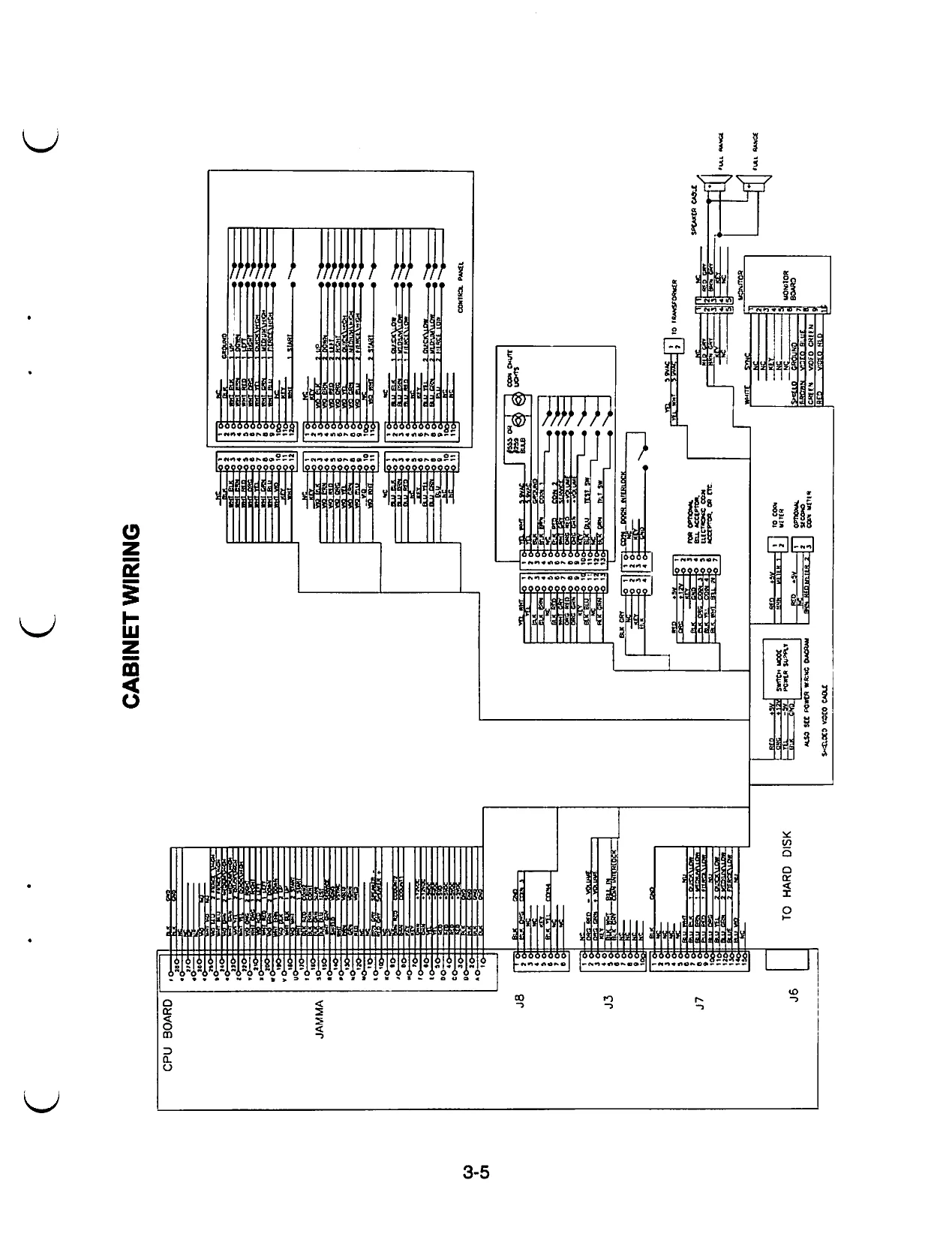
This page is a drawing, shown as the original scan.
ELECTRONIC RACK ASSEMBLY Before conversion to Killer Instinct 2.
- To MONITOR
- SPEAKE! CABLE
VIDEO SIGNAL CABLE
SAMA CONNECTOR
FAN GUARD FAN GRILL a) BN %© Kar %. & @) FAN MOUNTING BRKIS 4 Crees
°o |es!selo i |BEe!s= i |SS3 SS an SSi == SSS =S,i== SSS SSiS3+ 5 le JS="=SS [4
UNE VOLTAGE CABLE MAIN HARNESS: oS j oS | LL a
CPU_ASSEMBLY A~19650-40047
vote, Reo snp |] INDICATES PIN 1
- I rp come, RES ¥ 9 3 user H eon arenes g Eeaegd Ej
|| RacKET-HARD ORWE MOUNT we)
ELECTRONIC RACK ASSEMBLY
SESE, SSS TO COIN METERS
3-6 CY
ELECTRONIC RACK ASSEMBLY After conversion to Killer Instinct 2.
£] TO MONITOR
MAIN: HARNESS,
| 10. SPEAK | o] | S] | lo |
i LH ay ol i CPU_ASSEMBLY
| g | 1 | A-19650-40047 |
NOTE: RED STRIPE [J
INDICATES PIN 1 (at oO o
| FAN GUARD | lo | ° | to contne |
| FAN GRILL | rR) | OR oN, Beane: | PANEL CABLE |
| A | | | THE 440 stmacnt HEADER |
The eerPm CHT ANGLE HEADER con cacor, % 2ubgs ITO THE HEBON CABLE Cocxour y % ea eon macaract etecraar
| \ | (0) | 7) |
FAN MOUNDNG @RKTS e, wetmone y ‘ATES TO con po0R
E SPACER ASSEMBLY oe? mel oll | SPACER : |=s! 22 ==; SS
i S=Si SS PROGRAMMED HARD DRIVE ASSEMBLY
- 4 SS A-20337 ———s THE ASSEMBLY INCLUDES THE PROGRAMMED —— HARD DRIVE, THE RIBBON CABLE, —— AND THE CLEAR ENCLOSURE. SS 1S 0 [SS S"S5 |_ oi ELECTRONIC RACK ASSEMBLY
- TRANSFORMER (COINDOOR LAMPS) = a TO COIN METERS SO ee LINE VOLTAGE CABLE = . |
NOTES CN
WARNINGS & NOTICES
- For safety and reliability, substitute parts and modifications are not recommended.
- Substitute parts or modifications may void FCC type acceptance. .
- Use only MIDWAY Manufacturing authorized components and parts. Failure to do so will void warranty and may result in incorrect and/or unsafe operation.
- This game is protected by federal copyright, trademark and patent laws. Unauthorized modifications may be illegal under federal law. This also applies to MIDWAY logos, designs, publications and assemblies. Moreover, facsimiles of MIDWAY equipment (or any feature thereof) may be illegal under federal law, regardless of whether or not such facsimiles are manufactured with MIDWAY components.
NOTICE - FCC COMPLIANCE |. THIS KIT WAS TESTED | ILLER INSTINCT VIDEO CABINET AND FOUND TO COMPLY WITH FCC PART 15 CLASS A REQUIREMENTS. ; I. INSTALLATION HIS_KIT_INTO_ ANY OTHER PRODUCT DOES NOT GUARANTEE COMPLIANCE WITH FCC REQUIREMENTS. YOU ARE SOLELY RESPONSIBLE, AND MIDWAY WILL HAVE NO RESPONSIBILITY FOR FCC COMPLIANCE FOR INSTALLATIONS IN OTHER PRODUCTS. THE FCC COMPLIANCE STICKER SHOULD NOT BE INSTALLED ON THE CONVERTED PRODUCT UNTIL FCC COMPLIANCE IS VERIFIED.
NOTICE No part of this publication may be reproduced by any mechanical, photographic, or electronic process, or in the form of a phonographic recording, nor may be transmitted, or otherwise copied for public or private use, without permission from the publisher. FOR SERVICE: CALL YOUR AUTHORIZED MIDWAY DISTRIBUTOR. MIDWAY MANUFACTURING COMPANY 3401 N. CALIFORNIA AVE. CHICAGO, IL 60618 Killer Instinct 2™ © 1994, 1995 Nintendo/Rare ™Trademark of Nintendo Developed by Rare Manufactured and sold by MIDWAY Manufacturing Company under license. Matencee and Killer Instinct 2 ™ are trademarks of Nintendo Co., Ltd. The Rareware Logo™ is a trademark of Rare WU
”