Warlords Cocktail DP-177-1st-01A
Warlords (Atari, 1980) · Drawing Package · 1 pages · original scan
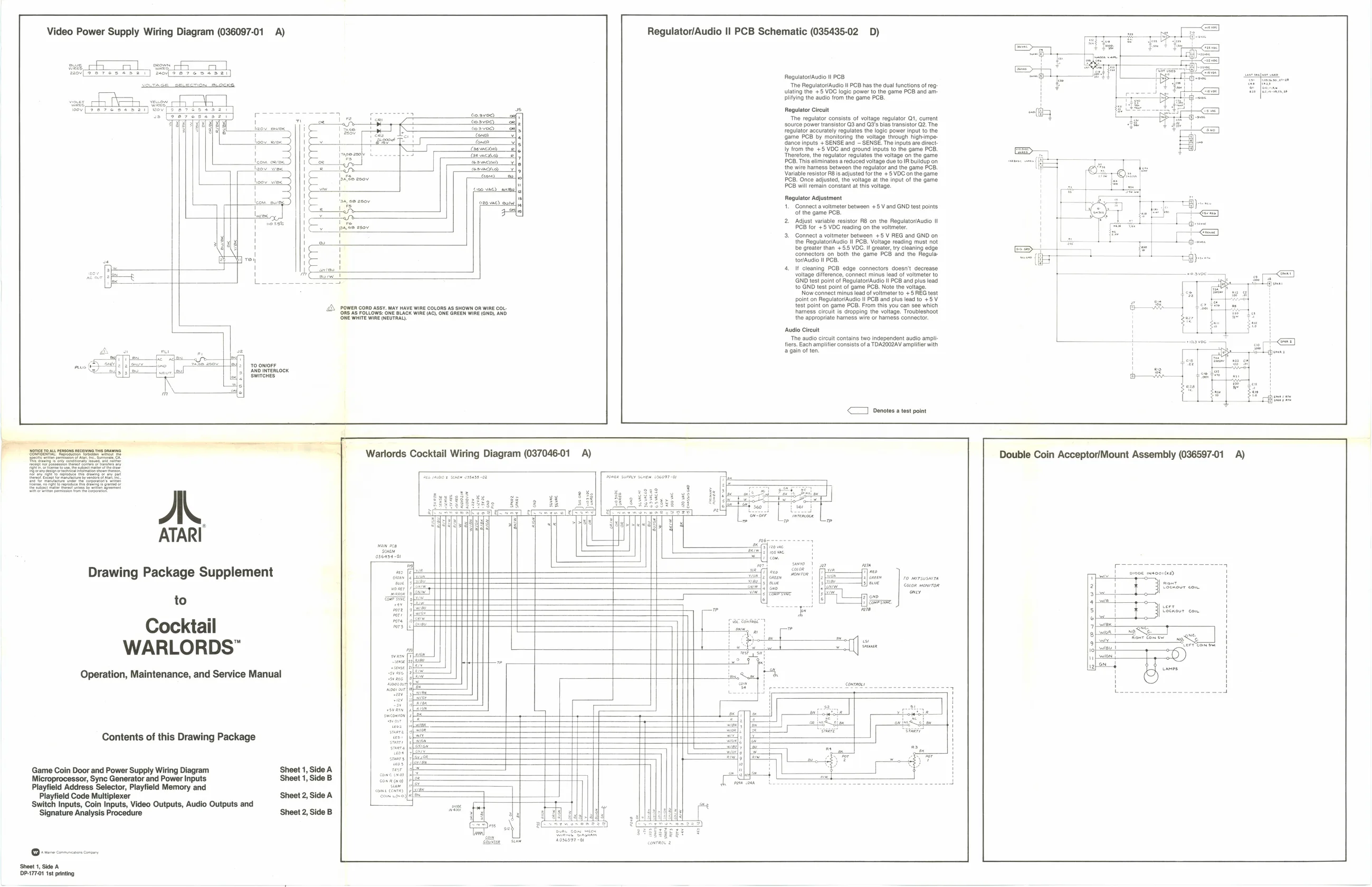
Video Power Supply Wiring Diagram (036097-01 A)
wos vee
Zeenerin
caswacyeo) om)
(uso vie) evil ‘20 ue) eh
a
A
ATARI
Drawing Package Supplement
to
Cocktail
WARLORDS”
Operation, Maintenance, and Service Manual
Contents of this Drawing Package
Game Coin Door and Power Supply Wiring Diagram Sheet 1, Side A
Microprocessor, Sync Generator and Power Inputs Sheet 1, Side B Playfield Code Multiplexer Sheet 2, Side A
Playfield Address Selector, Playfield Memory and
‘Switch Inputs, Coin Inputs, Video Outputs, Audio Outputs and ‘Signature Analysis Procedure ‘Sheet 2, Side B
‘Sheet 1, Side A DP.177.1 tt printing OWEN CORD ASSY MAY HAVE WIRE COLORS AS GHOWN OR WIRE COL {LOWS ONE BLACK WIRE (ACh ONE GAEEN WIRE (GND), AND ‘She Whive Wine NEUTRAL)
Warlords Cocktail Wiring Diagram (037046-01 A) Regulator/Audio || PCB Schematic (035435-02 D)
Regulator/Audio Il POB The Regulator/Audio i! PCB has the dual functions of reglating the +5 VOC logic owe othe game PB and amplifying the audio from the game PCI Regulator Circuit The regulator consists of voltage regulator Qt, current ‘source power transistor Q3 and regulator accurately regulates th {game PCB by monitoring the voltage through highimpe- {dance inputs + SENSE and ~ SENSE. The inputs are direct ly from the +5 VDC and ground inputs to the game PCB, ‘Therefore, the regulator regulates the voltage on the game PCB. This eliminates a reduced voltage due to IR buildup on the wire hamess between the regulator and the game PCB. Variable resistor RB's adjusted forthe +5 VDC on the game PCB. Once adjusted, the voltage at the input of the game PCB will main constant at this voltage. Regulator Adjustment ‘Connect a voltmeter betwoen +5 Vand GND test points ‘of the game PCB.
- Adjust variable resistor R8 on the Regulator/Audio II PCB for +5 VOC reading on the voltmeter.
- Connect a voltmeter between +5 V REG and GNO on the ReguetovAudl I PCB, Voltage reading must pot be at ‘connectors on both the game PCB and the Regula. Pcs.
- If cleaning PCB edge connectors doesn't decrease voltage difference, connect minus lead of voltmeter to NO test point of ReguatowAuio I PCB and plus ead to GND test point of game PCB. Note the voltage. Now connect minus load ofvoitmete to + 5 RE test point on Regulator/Audio ll PCB and plus lead to +5 V test point on game POB. From this you can see which hhamess circuit is dropping the voltage. Troubleshoot the appropriate harness wire or hamess connector.
Audio Circuit ‘The audio circuit contains two independent audio ampli: fiers. Each amplifier consists of a TDAZOOZAV amplifier with 2 gain of ten.
<] Denotes a test point
‘sve osease-01
jae Coton wonrTon os Double Coin Acceptor/Mount Assembly (036597-01 A)