Asteroids DP-143-3rd-01A
Asteroids (rev 4) (Atari, 1979) · Drawing Package · 1 pages · original scan
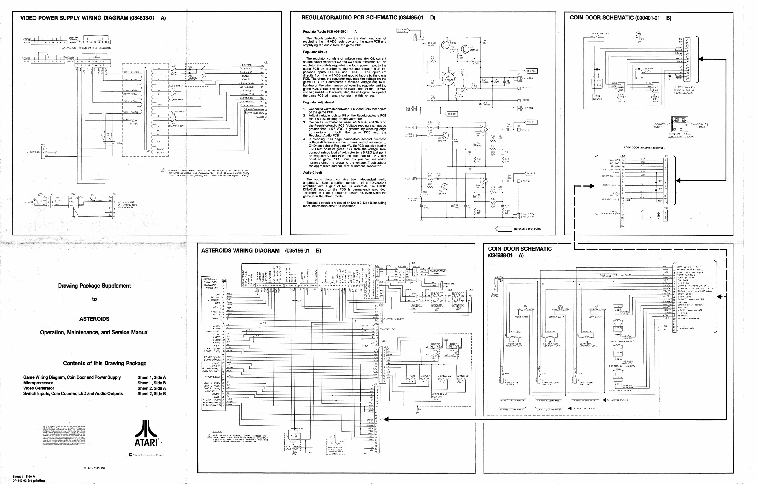
REGULATORIAUDIO PCB SCHEMATIC (034485-01 _D) COIN DOOR SCHEMATIC (030401-01 VIDEO POWER SUPPLY WIRING DIAGRAM (034633-01 A)
Regulator/Audio PCB 03448501 A FE
‘The Regulator/Audio PCB has the dual functions of regulating the +5 VDC logic power to the game PCB and amplifying the audio from the game PCB.
Regulator Circuit
‘The regulator consists of voltage regulator Qt, current ‘source power transistor Q3 and QG's bias transistor G2. The fugu acura requis te lal power input the
1@ PCB by monitoring the voltage through high im
Bedance inputs. '+ SENSE and “SENSE. Tho inputs aro directly trom the +5 VDC and ground inputs to the game lend Teese fo 0 Ig pos Movex 1 PB. Variable restator Rs adjusted forthe +5 VDC
‘on the game PCB, Once adjusted, the voltage atthe input of
the game PCB will remain constant at this voltage.
Regulator Adjustment
- Adjust variable resistor RB on the Regulator/Audio PCB = for'e5 VOC reading on ie voltmeter zal
- Gonnect a votmeter between +8 V REG and GND on 5 — ami come] ftom st the RegulatoriAudio PCB. Voltage reading shall not be ne 6 AAI} pp ——_} ans S| Bes Girt ‘greater than: BENDS Mt greater 77 cleaning, edge ay - 7 O_O. Eonnectore on. both’ the game. PCB. and. the emcee Sa Regulus Pa Ses.
- TPeleaning PCB. edge connectors doesnt decrease voltage diference, soiect minus lea of veto’
‘GND test point of ReguiatorAudio PCB and pius lead to
GND test point of game PCB. Note the voltage. Now ‘connect minus lead of voltmeter to +5 REG test point ‘on RegulatorfAudio PCB and plus lead to +5 V test point on game PCB. From this you can see which hhamess circuit is dropping the voltage. Troubleshoot the appropriate hamess wire or harness connector. COIN DOOR ADAPTER HARNESS
vss ess
AD conte como Aer ny HAVE WIRE COLORS Am Sx Sea Sea foe tech ee te tate RE E. ‘amauiaicas The audio circuit contains two independent audio ‘amplifiers. Each amplifier consists of a TDA2002AV amplifier witha” gain often. in Asteroids, tho AUDIO DISABLE input to the PCB Is permanently grounded. ‘Therefore, this audio circult is always on, even while the ‘game isin the attract mode.
‘The audio circu is repeated on Sheet 2, Side B, including
mote information about Its operation.
ASTEROIDS WIRING DIAGRAM (035156-01 B)
a
Drawing Package Supplement
to
ASTEROIDS
Operation, Maintenance, and Service Manual k
Contents of this Drawing Package sraer een) sranr eo) rant 10) saan etna)
i
Game Wiring Diagram, Coin Door and Power Supply Sheet 1, Side A
Microprocessor Sheet 1, Side B Video Generator Sheet 2, Side A Switch Inputs, Coin Counter, LED and Audio Outputs Sheet 2, Side B al kal links
| ail com cena Sara |e: con cen) 8 Set aaaddde [RERRE DDE CEE SE REECE URES ERECT TOL ETS ERR
2 mech Door
jee cee ee ATARI:
(© 1979 Ata ne
Sheet 1, Side A 1DP-143-02 3rd printing