Ataxx Rev. A
Ataxx (rev 5) (Leland Corporation, 1990) · Manual · 29 pages · 22 sections · original scan
ATAXX
Owner's Manual
Part Number B-701-00018-00 Rev. A
Your Responsibility for Maintenance
It is the owner’s responsibility to make sure that the specified maintenance is performed. The Troubleshooting Section of this manual provides details on these maintenance requirements. Also included in the Troubleshooting Section is information regarding other requirements for games operated under severe playing conditions.
Machine Information
Purchase Date:
Distributor:
Game Serial Numbers
Program: (see lower left corner of bookkeeping main menu screen)
PC Board:
© 1990 The Leland Corporation. All rights reserved. ATAXX™ is a trade- 2 mark of the Leland Corporation. a
Introduction
Welcome to the growing number of value conscious people who operate Leland Corporation products. We are proud of the advanced engineering and quality of each product we build.
Please take a few moments to read through this manual. It has been designed to acquaint you with the features of your new "ATAXX™" game and to help you make the most profit from this machine.
When it comes to service, remember that your Authorized Leland Distributor knows your game best and is dedicated to your complete satisfaction. He can provide quality parts, service, and any other assistance you may require.
The Leland Corporation
Please leave this owner's manual in the game at the time of resale. The next owner will also need this important information.
All information and specifications in this manual are current at the time of printing. However, because of The Leland Corporation’s policy of continual product improvement, we reserve the right to make changes at any time without notice.
Non-Leland Replacement Parts Notice
The Leland Corporation recommends the use of genuine Leland Corporation parts when replacing any malfunctioning component or assembly in this game. For safety and reliability, The Leland Corporation does not recommend or authorize any substitution parts or modifications of Leland equipment. Such alterations may adversely affect game play or cause serious injury, and will void your warranty. Unauthorized parts and/or modifications may also void FCC compliance.
FCC Warning
This equipment generates, uses, and can radiate radio frequency energy and if not installed in accordance with the Owner's Manual, may cause interference to radio communications. This game has been tested and found to comply with the limits for a Class "A" computing device pursuant to subpart "J" of part 15 of the FCC rules, which are designed to provide reasonable protection against such interference when operated in a commercial environment. Operation of this equipment in a residential area is likely to cause interference, in which case the user, at his own expense, will be responsible to correct the interference.
ATAXX Table of Contents
General Game Information Game Concept Features Assembly Instructions Maintenance and Upkeep
Troubleshooting A Note About Power Our Service Department Troubleshooting Flow Chart Mechanical Coin Counters
Bookkeeping and Diagnostics
Wiring Diagrams
Illustrated Parts List
Warranty Information Page Ono a
Ataxx Game Play
Ataxx is a thought-provoking, highly interactive 1- or 2-player strategy game based on a 7-by-7 tiled playing grid. The player attempts to secure a greater number of tiles than his opponent by moving his pieces in a manner similar to checkers.
When the game begins, each player starts with his pieces occupying one corner of the board. On any move, the player selects one of his pieces and moves it to any vacant tile no more than two squares away from his starting place. Unlike checkers, when the player moves his piece to an adjacent tile, a duplicate piece remains in the starting position to fill that tile.
\f a player should move more than one tile away, he will leave the starting tile vacant— an opening which can be utilized by his opponent.
When the player moves his piece to a new tile which is adjacent to his opponent, the player will vanquish his opponent's piece(s) and occupy its tile. If the player has no valid move available, he forfeits his turn. If his personal clock expires, he loses the game.
The personal clock (initialized to 100 units) works much the same as a chess clock and runs only when it is the player's turn. When the clock gets down to 25 units of time remaining, an “Insert Coin” message will flash on the screen, permitting the player to buy an additional 100 units of time.
The Red player makes the first move, followed by a move by the Blue player. The game continues until no valid moves remain. At the end, the player with the greater number of tiles occupied wins. A message announcing the winner will flash in the status box on the play screen. This screen will then fade to another screen depicting the results of the game and how it has affected the player’s rating and classification. A continuation prompt will then appear.
If a single player elects to continue, any time remaining from his previous game will be carried forward and a new game board will appear (if he won earlier— if he lost, the same game board will reappear). If he won, his subsequent computer opponent will be one level of difficulty higher than his previous level; the opposite is true if he lost. This sequence will continue until the player has played all available screens.
\f two players elect to continue, any left over time from the previous game will be carried forward. The loser of the previous game may then select a new game board by rolling his track ball to cycle through the screens. A new game board may be chosen using the “Select” button.
A player's performance is rated the same way as in chess, with five distinct classification levels: Champion, Ace, Expert, Fighter, and Reserve. These ratings are based on the number of points gained in each round of play. The High-Score list will consist of those top-ranked players and will display initials, rating, and classification.
Features Information
Two sets of player controls beckon new players to join the game. Individual scores are kept for each player. New players can enter their initials and have their outstanding scores appear on the rating classification board.
Normal operating checks are made easy with complete diagnostic screens. All player controls and both coin mechanisms are easily tested.
Other features of Ataxx include:
° 21 different game boards. One or two-players. ¢ Player's personal clock time length adjustable through game set-up menu. Prompts to purchase additional time throughout game. When playing against the computer, the level of difficulty changes depending upon the skill of the player. Five levels of compuier skill’ versus players are tabulated on the "Al" (Artificial Intelligence) Statistics screen.
Assembly Instructions
- Remove all parts from the shipping containers and check for damage. Notify your distributor (and the shipper) immediately if you find any parts broken.
- Keys for the coin doors are taped in the coin return slots. Inside the coin door you'll find the rear panel keys attached to the door with a clip (see page 13). The AC power cord will be found inside the rear panel. Close the rear compartment before turning on the game.
- Lift the monitor plexi and clean or dust any debris that may have settled on the monitor during shipping. This would also be a good time to gently wipe down the inside of the monitor plexi as well. Use only a soft, dry cloth to wipe the plexi to prevent scratching.
To lift the monitor plexi, reach through the upper coin mech door and an inner panel opening to unlatch the player control panel. Latch locations are shown below. Swing the panel as shown. With the player controls accessible, you can see the bottom edge bracket. Slide the plexi up until the bottom edge of the plexi clears the bracket, then lift out. Re-install in the reverse order.
- Plug in the'game and verify proper operation by going ” through the built-in diagnostic screens (see page 13). Check coin mechanism operation by feeding each one with a few coins.
- This is also a good time to check your coins-per-credit and game play time settings. "Ataxx’ is shipped with most adjustments set in the middle of their range.
Access to fluorescent bulb is by removing the top plexi retainer screws and retainer. Lift plexi Straight up and out. Reassemble in reverse order.
For control access reach through coin door, unlatch both sides, swing control panel up and forward. ‘On/Off rocker switch on rear panel.
Power supply and main circuit board located inside, behind lockable rear panel. Panel latch
Panel hinge
Inner panel opening Panel latch
Maintenance and Upkeep
Maintaining your ATAXX game is of utmost importance in order to enjoy good, steady earnings. A dirty cabinet, sticky coin mech, or poorly adjusted player controls are all suspect when a significant drop in revenue is noticed.
The following are recommended procedures to follow when servicing your machine:
Every Collection— Make sure that the cabinet and especially the control panel and glass are clean and free of gum, grease, and dirt.
Play the game. Check the trackballs and buttons for proper adjustment and response (see the buttons and controls test in the Diagnostics sections).
Clean and adjust the monitor to insure that the picture is “tich" and inviting.
Once a Month— Check the inside of the cabinet for dirt and dust. HINT: Carry a portable “Dustbuster”-type vacuum.
Confirm proper adjustment of game volume, brightness, and contrast controls.
Use diagnostic screens to help you adjust color or horizontal/vertical size and position if required.
Check the screen corners for "rainbows" or color "fringing." This can indicate a need for degaussing.
Look for proper fluorescent lamp operation. The reduced brightness caused by one inoperative bulb is highly noticeable. Also, check coin slot lamps.
At first these steps may seem annoying or excessive, but when viewed with respect to the income generated by a clean, well-maintained machine (as opposed to income lost by a dirty, “trashed” game), the benefit of spending a few extra minutes will be seen as a wise investment.
Troubleshooting
A Note About Power
DC Power
The microprocessor in this machine operates most efficiently when the power supply is providing a steady +5.00 VDC to 5.05 VDC. When checking the DC power, always put your leads across the +5 VDC test points on the board and be sure that the +5 volt supply is between +5.00 VDC and +5.05 VDC. Also, be sure that there is less than .005 volts AC riding on the +5 volt line. If you do find AC on the DC line, inspect the filter capacitor or the rectifier on the power supply. Low voltage and AC on the DC lines are the main causes of the following problems:
- “Garbage” on the monitor screen
- Computer freeze-up
- A variety of seemingly unrelated problems
AC Power
Connect this game only to a grounded three-wire outlet which provides between 108 and 132 volts AC. If you have only a two-wire outlet, we recommend that you hire a licensed electrician to install a grounded outlet. This will reduce the possibility of a player receiving a shock. The possibility exists that players may receive an electrical shock if this system is not properly grounded.
Our Service Department
For parts, service, and technical information, first contact your authorized Leland Corporation Distributor. If additional technical aid is required, please contact the Leland Corporation Technical Support Department at (619) 562-7000, Monday through Friday, 8:00 a.m. to 5:00 p.m. Pacific Standard Time.
To provide you with the quickest possible response to your questions, please have the following information ready when you Call:
- Your game name and serial number
© Any reference materials and a list of observations
Troubleshooting Fiow Chart
Don’t Touch That Switch!
Before you reach for the power switch, take a look at the game. Open it and check for loose wires, bad connections, or burned spots. Also look for spilled fluids or signs of vandalism. These quick checks could save you a lot of time.
Once you've eliminated the obvious, it's time to do some detective work.
Never take anything for granted. This is easy to do if you're in a hurry. Locating a broken wire or loose connection at the beginning could save you many expensive hours looking in the wrong place.
Good Picture Check Fuses and Coin Up Go to Bookkeeping Power Connections Start Game & and Diagnostics Listen for Sounds.
Check for Closed Switches on Coin Door & Control Panel. Also Check for Loose ICs/Bent Pins. Turn Up Screen Brighiness On Monitor,
‘Check Monitor Power, Fuses & Connectors. Check Picture Tube for Damage. Check Wires & Connectors From PCB 1 to Monitor. Don't Overlook Ground.
Troubleshooting Tips
General Troubleshooting Monitor screen filled with “garbage” —
¢ Press reset switch on main circuit board (see figure at right).
- Verify proper adjustment of monitor sync controls.
- Check power supply voltages.
- Check closed switches on the control panel or coin door. :
- Look for loose connections on connectors VID1, VID2, M1 and M2. Examine J1 Pins 16-18, 20-22. ¢ Measure the voltage on Pins 1 & 10 on Connector J1. If the voltage is less than +5 VDC, check the switching power supply and its voltage adjustment.
No sound—
¢ Check for loose connections. ¢ Low +12 VDC supply.
- Defective speaker or volume pot.
No control or function switches (includes coin switches)—
¢ Check all connections (especially ground). ¢ Check wire continuity between board and switch. ¢ Look for closed or broken switches.
- Check the input buffers (see “Buffers” below).
Monitor Troubleshooting No picture—
- Proceed carefully, high voltages present.
- Check all power connections including isolation transformer. « Examine the picture tube filament, verify that it is on.
- Listen for the sound of the horizontal oscillator/flypack (a high pitched squeal).
Sync problems—
- Check sync and ground connections (see wiring diagrams on Pages 18 - 20). « Check sync polarity. ¢ Check the video output buffer.
Buffers An input or output (I/O) buffer is the component that produces/receives the signals required to connect the game computer to the outside world. Static discharges and other forms of electronic "stress" encounter the buffers first. For these reasons the I/O buffers sometimes fail (while protecting the more delicate electronics). An oscilloscope is recommended to verify proper I/O function. audio amplifier 7
GoEREBuE Ey
SERIAL NO,
Main Circuit Board
About Mechanical Coin Counters
We have not installed mechanical coin counters on this game for the following reasons:
- The bookkeeping program for this game is extremely accurate and includes not only the number of coins dropped and the dollars earned, but also keeps track of the number of coins in a given period. (See “Bookkeeping” in the Diagnostics Section.)
- Mechanical coin counters can produce an inductive “kick” that could damage circuit board components, "checkerboard video" being the most common problem.
If your situation requires mechanical coin counters, please use the following diagram. (Diodes may be 1N4001 to 1N4004.)
+5 VDC terminal Coins #1 on switching wer Sul METER Power supply
000001
Coins #2 METER 000001 J1-AA
Coin Switch No.
J1-Z
Attract Mode Volume Control
Cabinet keys (held by clip) Service Button
Cash Door
Service Switch Location
MAIN MENU
CHOOSE FUNCTION WITH JOIN BUTTON ENTER FUNCTION WITH SELECT BUTTON
BOOKKEEPING ATAXX DIAGNOSTICS GAME SET-UP GAME STATISTICS
RESTART THE GAME (CANCEL CHANGES AND RESTART GAME
BOOKKEEPING. ‘CHOOSE FUNCTION WITH JOIN. BUTTON ENTER FUNCTION WITH SELECT BUTTON
LIFETIME PERIOD
‘COINS COINS DROPPED - MECH 1 000 = MECH 2
‘TOTAL COINS DROPPED
‘TOTAL CREDITS GIVEN: MECH 000 ~MECH2 000
RESET COIN MECH’. DOLLARS COLLECTED RESET COIN MECH 2 DOLLARS COLLECTED
‘SET COINS/TOKENS PER DOLLAR: ‘ACOINS PER DOLLAR
RETURN TO MAIN MENU Bookkeeping and
Diagnostics
To enter the Bookkeeping and Diagnostics Sections:
¢ Press either "Select" button on the control panel
¢ Press and hold the service button (located inside the front door-- see figure at left)
¢ Release both buttons
The Main Menu will appear on the screen. Follow the instructions on this menu to select and enter the desired function. All screens contain instructions for using them on the top or bottom-most lines.
Bookkeeping
The Bookkeeping function is your game accountant. It records the lifetime earnings of your game and allows you to keep track of weekly, monthly, or location earnings by using the resettable “Period” totals.
This function does not affect the number of coins per credit. (See “Game Set-up” for further informa- 13 tion.)
ATAXX DIAGNOSTICS
CHOOSE FUNCTION WITH JOIN BUTTON ENTER FUNCTION WITH SELECT BUTTON
BUTTONS AND CONTROLS TEST
PROCESSOR MEMORY TEST
VIDEO ALIGNMENT SCREENS
AUDIO SUBSYSTEM TEST
‘VIEW BACKGROUND SCREENS
RETURN TO MAIN MENU
PLEASE PRESS THE FOLLOWING BUTTONS:
‘SELECT 1 BUTTON (RED)
Je) MECH 1 COIN SWITCH (REO) MECH 2 COIN SWITCH (BLUE) ‘SERVICE SWITCH ‘o~ TRACKBALL RANGE OF MOTIONe+ ‘TRACKBALL! (RED) ‘TRACKBALL? (BLUE)
t
PRESS SERVICE OR SELECT BUTTON TWICE TO EXIT
PROCESSOR MEMORY TEST
‘TRAM TESTED ‘TRAM GOOD TESTING MASTER ROM MASTER ROM GOOD
‘QRAM TESTED ‘ORAM GOOD ‘SCRATCH RAM TESTED ‘SCRATCH RAM GOOD
COLOR RAM TESTED. COLOR RAM GOOD ‘SLAVE MEMORY TESTED ‘SLAVE ROM GOOD ‘SLAVE RAM GOOD BRAM TESTED ‘BRAM IS GOOD.
EEPROM TESTED EEPROM IS GOOD
JOIN BUTTON TO REPEAT » SELECT BUTTON TO EXIT Diagnostics Menu
Calling up the Diagnostics menu will open a very complete and easy-touse set of tests to make adjusting, troubleshooting, and servicing your machine quick and simple.
You will notice that the diagnostics section has a sub-menu of its own.
Buttons and Controls Test
This test provides a quick examination of the condition of all player buttons and controls.
As each itemis tested, its change of status is shown on the screen. Any blinking or intermittent screen indications mean that switch cleaning or replacement is required.
Trackball arrows and icons
Processor Memory Test
The erasable programmable read only memory (EPROM) and random access memory (RAM) ICs are storage areas for the actual game guidelines and are accessed by the microprocessor. The percentage of field failures in these areas is very low, but when problems do arise they can be difficult to track down. This processor memory test samples the action of the microprocessor and notes any malfunctions.
"xX" Indicates corner of screen
PRESS SELECT BUTTGN jo END =
Indicates misadjusted contrast Video Alignment Screens
The picture on the video monitor is the most important and most neglected part of any game. It has been proven that a dirty, misaligned, or unfocused screen is the biggest cause for reduced collections— players will simply walk away if the game is not operating properly.
Making the effort to go through the following adjustment screens can make a big difference in revenues. Use all three screens to adjust your picture and then go to the Background Screens section to make the game look “rich.”
Cross Hatch Screen Use the cross hatch screen to adjust focus, alignment, size, and contrast. Wavy horizontal lines denote misadjusted contrast. The screen's background should be black and the lines solid white.
The four “x" marks will be in the screen corners when vertical and horizontal size and position adjustments are correct.
If the crosshatch squares are rectangular, use the size controls to make them square, then the position adjustments to put the "x's in the corners.
Adjust the screen or brightness control so that the green color bar shows green in the center and tapers to black on the ends.
Use the red cutoff control to adjust the red color bar to the same intensity as the green color bar.
Use the blue cutoff control to make the gray color bar appear gray (not brownish).
Adjust the red and green drive controls slightly to make the white blocks white.
‘AUDIO SUBSYSTEM TEST.
PRESS SELECT BUTTON TOEND
TESTING AUDIO PROMS
‘AUDIO PROMS OK ‘AUDIO RAM OK
COMMUNICATIONS TEST PASSES @ BIT DACTEST (TONES) 0-2 CHANNEL, 10 BIT DAC TEST (2 SEC TONES) DAC INTERACTION TEST (3 TONE PULSES) (0-2 CHANNEL
‘MUSIC TEST (ATAXX THEME)
‘VIEW BACKGROUND SCREENS PRESS JOIN BUTTON FOR NEXT SCREEN PRESS SELECT BUTTON TO EXIT APPROXIMATELY 30 STATIC SCREENS WILL SEQUENCE PAST.
GAME SET UP
‘CHOOSE FUNCTION WITH JOIN BUTTON ENTER FUNCTION WITH SELECT BUTTON + ++0 COIN SETS FREE PLAY + «+ ‘COIN MECH SETTING 1 COIN FOR 1 CREDIT
GAMEPLAY TIME... 0... 2:00 ATTRACT MODE SOUND. . . . YES
RETURN TO MAIN MENU Audio Subsystem Test
The sounds are the second most
Background Screens
In this test, the background screens are shown while the EPROMS containing the information for these screens are displayed at the right side of the screen. This test is not only helpful when looking for glitches, but may also be viewed as a visual test of the colors and picture clarity after the Video Alignment test has been completed.
Game Set-up
This section is vital to the condition of your cashbox. When used in conjunction with the Bookkeeping section of the Diagnostics package, the Game Set-up function will keep your game on the top of your earners list. The coins-per-credit settings range from 1 coin/1 credit to 20 coins/20 credits. Game play time can be adjusted from 1 to 4 minutes in 30 second increments. Difficulty level range is 1 to 8. Use “Join” button to move highlight to desired function, use the "Select" button to step through choices.
GAME STATISTICS (CHOOSE FUNCTION WITH JOIN BUTTON ENTER FUNCTION WITH SELECT BUTTON
1 PLAYER 2 PLAYER 0 0 {RED} {BLUE} 0 0
AFTER WIN, AFTER LOSS. ‘COMPUTER
RESET GAME STATISTICS
ERASE HALL OF FAME ON EXIT - NO
DISPLAY Al RECORDS
RETURN TO MAIN MENU
‘AIRECORO STATISTICS
| ToP | AVG, | AVG, |
| RATING | RATING | «RATING |
| BEATEN | BEATEN | PLAYED |
RATING WINS Losses
PRESS SELECT BUTTON TO EXIT Game Siatistics
This section lets you know how well you've done in setting your game for maximum eaming power.
Artificial intelligence Statistics
This screen compares the five levels of computer "skill" versus the human opponents played against. This information can help you determine if the game difficulty level and play time are set properly for a particular location.
This page is a drawing, shown as the original scan.
This page is a drawing, shown as the original scan.
Player Control Wiring
Jt-Lo————._ Green J1-M——__—-. Blue J1-K (+ Violet J1-Jq-———- Yellow J1-Dp>}————- Red J1-23 Black To Red A-Wra Wied Trackball J1-VE}-—— Red/Black /
Select (Red)
Join (Red)
BPI
Ji-R [+——— Green Ji-S [}——— Blue J1-P O Violet Ji-N [— Yellow J1-3 EL———._ Rea J1-24 [}——- Black J1-U O+—— whiteBiue a To Blue Trackball
Ji-T [+—— BlueMhite _~
Select (Blue)
Join (Blue)
J1 Connector
| bere | (GND) Black | alt | Black (GND) | pois |
| pe1-8 | (GND) Black | B|2 | Black (GND) | pet-11 |
| pert | (+5VDC) Red | cl3 | Red (+5VDC) | apts |
| RPS | (+5VDC) Red | pl4 | Red (+5VDC) | Dc1-10 |
E]5
| Fié | Orange (+12VDC) | pe1-12 |
Key] H 7
| RP1-4 | Yellow | ule |
Violet Rea | RP1-3 K
La RP1-1 Green L
Blue
| RP1-2 | volo | M |
ellow BP1-4 N tus | BPI-3 Violet P
| Tack | Tpit | Green | R | |
| BP1-2 | Blue. | s | ||
| BP1-9 | (Blue Select) Blue/White | T | Red (Video R) | voit |
| BP1-7 | (Blue Join) White/Blue | u | Blue (Video B) | vinta |
| Rena | (Red Select) Red/Black | Vv | Green (Video @) | vio |
| RP1-7 | (Red Join) White/Red | Ww | ||
| SRV1-2 | (Service) Green/Yellow | x | White (V Sync -) | vos |
| Y | Gray (H Sync -) | vi01-4 | ||
| ON1-2 | (Coin 2) Orange | z | Black (Video GND) | yiny.¢ |
- Coin 1) Yellow/Black
| CNt-1 | (Coin | 1) | Yel | AA | Black (Red PLGND) _ py. |
Black (Blue PLGND) _ gp1.6 Black (Coin GND) SRV1-4
SPK1-1 (Speaker -) Black White/Violet_ (Speaker +) SPK1-2
a
Male Molex Connectors Typical Pin-Out
Wire End
Wire End
Wire End Wire End Wire End a GmvYel ao Whi/Vio “a - oe : Of Black Ole Black : n 2 Yellow/Black 1 5 a 1 8 a ; |
See main board layout for board connector locations
Speaker, Switches Wiring Diagram
SPK1 SPK2 SPK3 SPK4 JFFOR Black Black 31-28 Oe Wht/Vio WhtVio ; CN1 CN2 Coin Switch #2 J1-Z O+————Orange > Speaker J1-AA L-—-_—Yo/Bik- ° % = Service Coin Switch #1 * |?
Switch VOL2 VOL1 s
a 1Ohm 5W O—Grn/Yio—f{7) (71) Volume [sa nam 2) Control Wht/Vio—t 3 | Gray 8 Ohm 10W J125O— Black J1-XO——— Grn/Yio
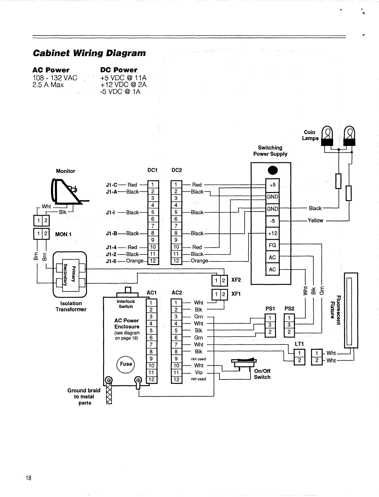
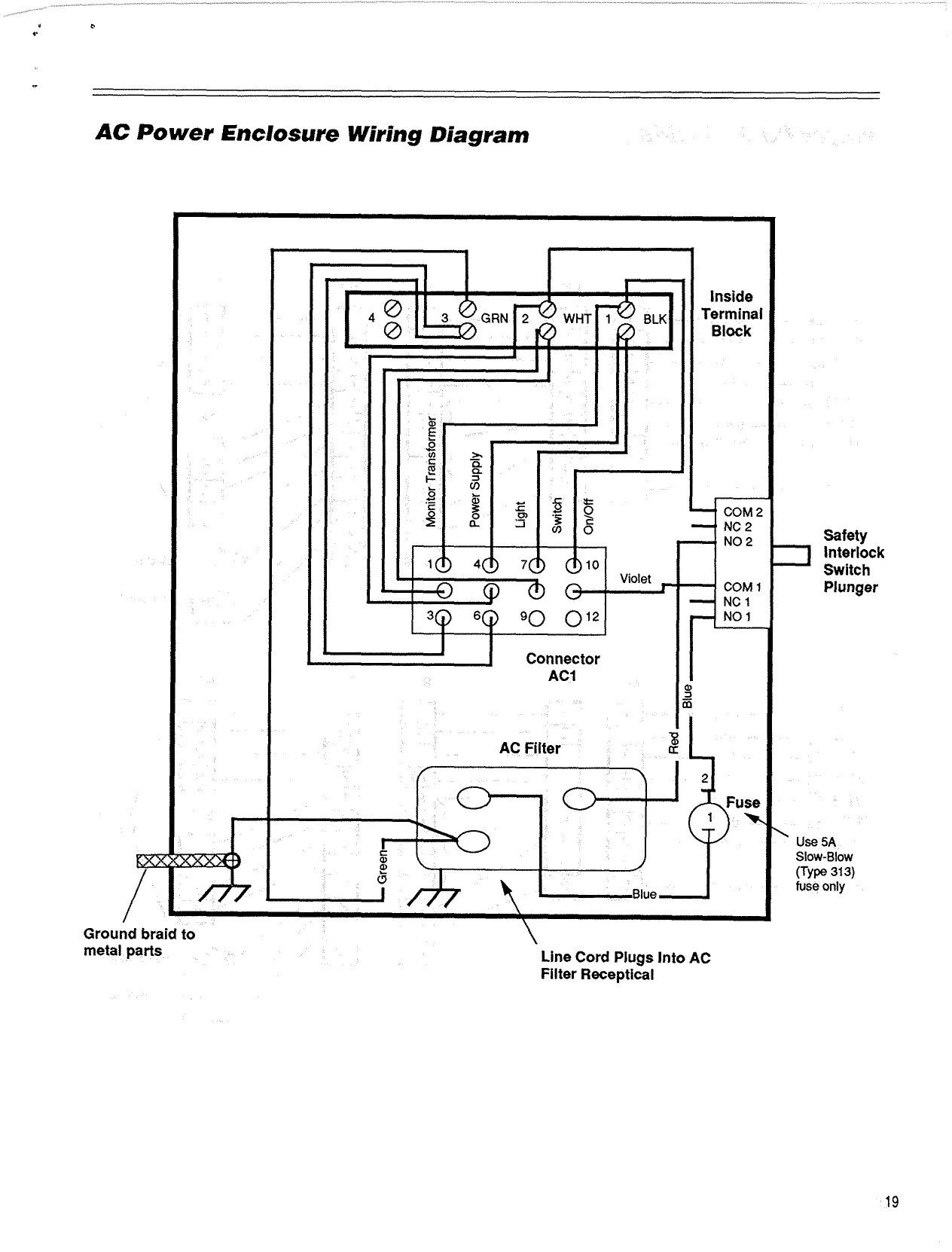
Wiring Diagrams
DC Power pci 0c2 J1-C O-— Red J1-A o——— Black
J1-1 O—— Black wae to switching power supply terminals J1-B O——— Black
J1-4 O— Red J1-2 2—— Black J1-6 O—— Orange:
Video
J1-160-——_ Red J1-189-——. Green a | 2] J1-170-——._ Blue 3] a
G Video (Green) | 3} Video (Biue) M1 (to monitor) J1-210-———_ Gray J1-200-——— White J1-220-————_ Black
Iustrated Parts List
lamp fixture, fluorescent marquee retainer C-909-00000-00 marquee plexi B-405-00016-00 B-204-00005-00
marquee graphics B-603-00016-00
speaker C-701-00000-00 speaker grill B-423-00011-00
19° monitor C-980-00039-00
monitor plexi B-204-00005-00
monitor bezel B-211--00001-00
trackball red C-743-00001-00 trackball blue C-743-00002-00
join button white C-703-00010-00 control panel (metal only) B-409-00007-00
control panel graphics B-604-00028-00
select button blue C-703-00008-00
select button red C-703-00007-00
coin door & mechanism C-980-00002-00
ly B-101-00010-00
join button white C-703-00010-00
rocker switch C-707-00000-00
switching power supply A-101-00006-00
fuse, slow-blow, 5 amp C-901-00000-00 fuse holder C-903-00000-00
ac power enclosure A-110-00005-00
ac power cord D-550-00001-00
safety interlock switch C-709-00002-00
Other Parts power supply gnd harness A-301-00135-00
monitor gnd harness A-301-00139-00
ac main power harness A-301-00130-00
de power harness A-301-00122-00 power supply harness A-301-00131-00
cntrl panel harness player red A-301-00127-00
cntrl panel harness player blue A-301-00128-00
volume control assembly A-110-00002-00 isolation transformer C-710-00001-00
speaker harness A-301-00123-00
gnd volume harness A-301-00138-00
main harness A-301-00132-00
video harness A-301-00125-00 main circuit board A-210-00023-00
volume control harness A-301-00126-00
ac line filter C-905-00002-00
ac power harness A-301-00129-00
The Leland Corporation Warranty
The Leland Corporation warrants that whenever the power supply and/or the printed circuit boards and/or all parts contained therein are furnished with its product, that such part or parts will be free from all defects in materials and workmanship for a period of sixty (60) days from the date of shipment. The Leland Corporation’s warranty of above parts is subject to the normal use and service of its product. No other products or parts thereof are warranted. If the products described in this manual fail to conform to this warranty, The Leland Corporation's sole liability shall be, as mutually agreed, to replace or repair such products which are returned to The Leland Corporation during stated warranty period, provided:
A. The Leland Corporation is notified in writing upon discovery by the buyer that said products are defective.
B. The defective product or part is returned pre-paid to The Leland Corporation’s plant with a Leland Corp. Returned Merchandise Authorization (RMA) number clearly visible on the outside of the package.
C. The Leland Corporation's examination of the returned product(s) or part(s) determines, to our satisfaction, that the alleged defects existed and were not caused by accident, misuse, neglect, alteration, improper repair, installation, or testing.
The Leland Corporation is not responsible for bent pins on ICs not installed by our employees. In no event shall The Leland Corporation be liable for loss of profits, loss of use, or incidental or consequential damages.
EXCEPT FOR THIS WARRANTY, THE LELAND CORPO- RATION DISCLAIMS ALL OTHER WARRANTIES, EX- PRESSED OR IMPLIED, INCLUDING THE IMPLIED WAR- RANTIES OF MERCHANTABILITY AND FITNESS FOR A PARTICULAR PURPOSE, AND ALL OTHER OBLIGA- TIONS OR LIABILITIES ON THE LELAND CORPOR- ATION’S BEHALF, AND IT NEITHER ASSUMES NOR AUTHORIZES ANY OTHER PERSON TO ASSUME FOR THE LELAND CORPORATION ANY OTHER LIABILITIES IN CONNECTION WITH THE SALE OF PRODUCTS MANU- FACTURED BY THE LELAND CORPORATION.
The Leland Corporation 1841 Friendship Drive EI Cajon, CA 92020 (619) 562-7000 aa ae
ATAXX
Owner's Manual
Addendum
Part Number B-701-00020-00 Rev. B
" A Word About Compatibility...
The edge connector on the game circuit board is not directly compatible with the JAMMA standard pinout. All functions on the game circuit card are accurately detailed in the owner's manual.
Adapting the game to the JAMMA standard pinout requires the use of the included adapter board. The pinouts of the adapter board and harness are indicated on the following page
ATAXX Kit Parts List
Part Number
A-210-00029-00 A-210-00030-00 A-301-00153-00 B-603-0001 9-00 B-604-00028-01 B-701-00018-00 B-701-00020-00 C-741-00003-00 C-703-00007-00 €-703-00008-00 A-110-00002-00 Qly. Description
ATAXX Circuit Panel JAMMA Interface Harness, Kit Marquee Graphics Control Panel Graphics Owner's Manual Owner's Manual Addendum Joystick, Digital Pushbutton, Red Pushbutton, Blue Volume Control w/Harness
@ ‘ ATAXX" JAMMA Adapter Board Coennectar/Harness
Solder Side Ji Component Side
| _{GNO) Black | KAA | (GND) Black | _ | ||
| __. | (GND) Black | — | |ede | be | ee _SGNO) Black, |
a (48VDC) Red. _leol3 (:SVOC) Red .
| ___usvogyned | fp | fg | J ene ot |
E|S
| (412V0C) Orange | 6 | (U2VDC)_ Orango |
Koy 7 Ky.
| (Spoakor_-) Whiloftiack, | 40 | _ | _{Speaker_+) WhitofViolot |
"4
| (Video Groen) Greon | 42 | _.. | (ideo. Bow). Be. | _ |
| _—Wisloo Syne) Grey | 13 | J— | __Vidco.Blue) Blo |
Servier Ovyiteh Ginttlo__. Wider. Ground) Black
| (Coin Switel #2) BindWht | 16 | {Coin Switch | 1) Greyitod |
(QP Control Up) Green (QP Control Down) Bia (2P Control Lett) Violet _ 48 (IP Control Up) Bln 49 (IP Control Down) Gro0n 20 (10 Control Lott) Yollow
(2P Control Nigh) Yellow.
- ion) Diu _{8lvo “Join” Button), wayne | pp | 24 _(OP Control Right) Violat N<xM Ee CHHNBVAZECACIT B
{GND} Black IGN) Black
Plug adapter board onto edge connector of main circuit board. Adapter board edge connector is now game 1/0 (standard JAMMA). Plug harness onto adapter board and connect wires as indicated above.
© 1990 The Loland Corporation, ATA} is a trademark ol [tho Leland Corporation
WHTMO g—______ WHT vio GF
VOLUME CONTROL
8 OHMS 10 WATTS
L-PAD WHT/BLK wo ~ enna 1 0HM5W
SPEAKER
WIRING DIAGRAM
ATAXX JAMMA ADAPTER BOARD VOLUME CONTROL