Tempest Cocktail DP-193-1st-01A
Tempest (rev 3, Revised Hardware) (Atari, 1980) · Drawing Package · 1 pages · original scan
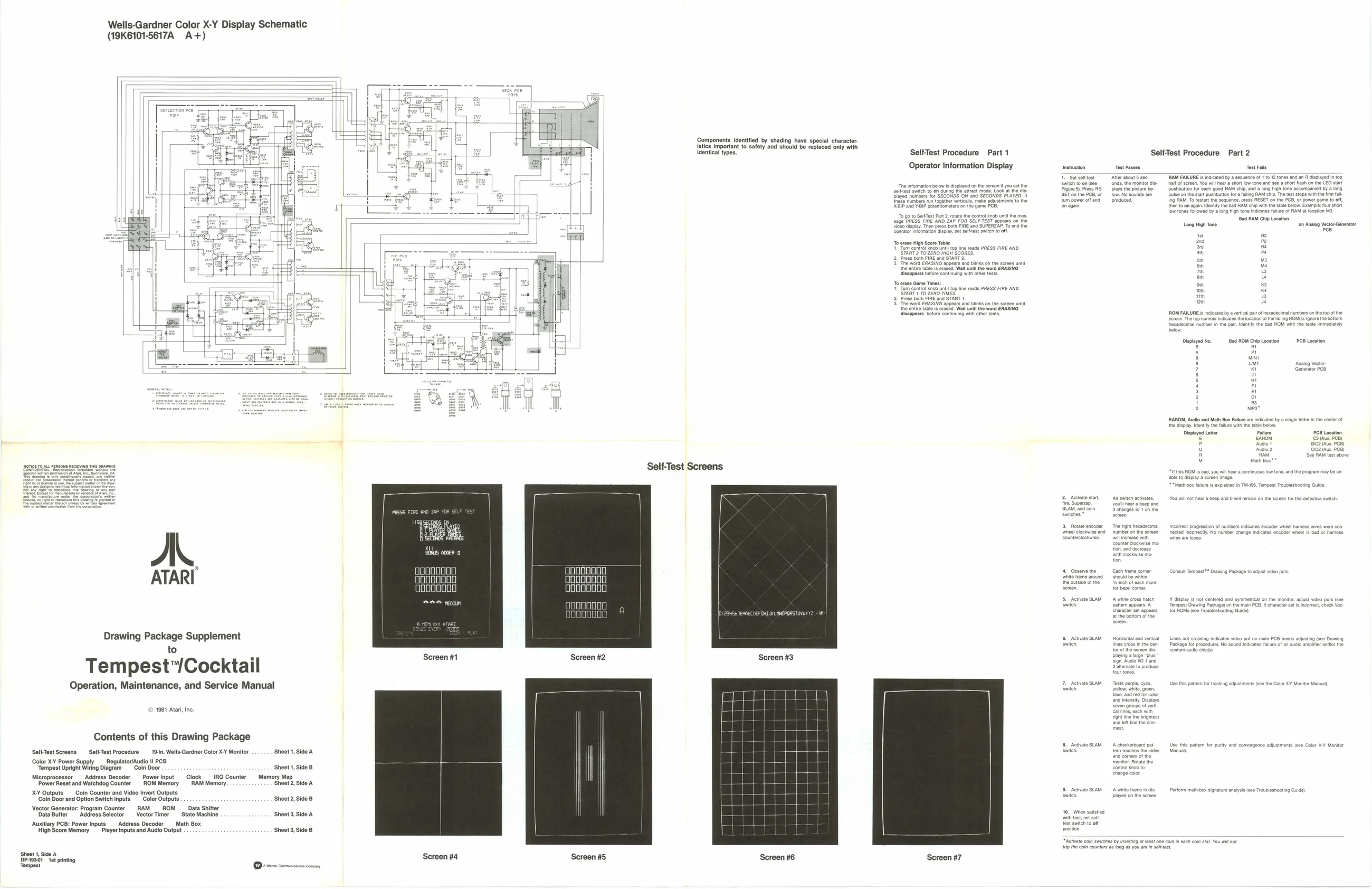
Wells-Gardner Color X-Y Display Schematic
(19K6101-5617A A+)
A.
ATARI
Drawing Package Supplement
Tempest™/Cocktail
Operation, Maintenance, and Service Manual
1981 Atari Inc.
Contents of this Drawing Package Self-Test Screens SellTest Procedure 19: Wells-Gardnor Color XY Monitor Color X¥ Power Supply Regulator/Audio i! PCB
| “Tempest Upright Wiring Diagram | Coin Door | Sheet 1, Side 8 | |||
| Microprocessor | Address Decoder | Power Input | Clock | IRQ Counter | Memory Map |
| Power Reset and Watchdog Counter. | ROM Memory | RAM Memory | ‘Sheet 2, Sido A |
XY Outputs Coin Counter and Video Invert Outputs Coin Door and Option Switch Inputs Color Outputs Vector Generator: Program Counter RAM ROM _ Data Shifter,
| Data Butler | Address Selector | Vector Timer | State Machine | st |
‘Auxillary PCB: Power Inputs Address Decoder Math Box
High Score Memory Player inputs and Audio Output
Sheet 1, Side A
Sheet 2, Side B 19, Sido A
Sheet 3, Side B
‘Shoot 1, side A DP-10301 tt printing Tompost gooo0000 gooo0000 oooooo0o goooo000 Oooo0000 ogo00000
eee reonn goo00000 ooooo000
Screen #1 Screen #2
Screen #4 Screen #5 Component istics important to safety and should be replaced only with identical types.
Self-Test Screens ntified by shading have special character
Screen #3
Screen #6 SelfTest Procedure Part 1
Operator Information Display
Bid mater or SECONDS ON ra SECONDS MAYES. Si" and YP potentometars on = Toepin Soe Pat 2. tee PRESS HIRE AND ZAP FOR St
To arase High Score Table: 7 SYART2 TO ZERO HoH ‘Scones Es AASING 29 ed: Wa an he word ERASING rob ntl topline eads PRESS FIRE AND
ithe word ERASING
‘Screen #7 Self-Test Procedure Part 2
Set sotest Aor aout 8 one
Stam, and or
- Observe the Each frame core
‘ht ine the brgest ‘nd tino tho am
tes stn foot Long High Tone on Anaog Vector Sonarator Pee
Displayed No. Bad ROM Chip Location PCB Location
eure C8 Location PCB)